Embedded Programming
Task:-
Group assignment:
Demonstrate and compare the toolchains and development workflows for available embedded architectures.
Document your work to the group work page and reflect on your individual page what you learned.
Individual assignments:
Browse through the datasheet for your microcontroller.
Write a program for a microcontroller, and simulate its operation, to interact (with local input &/or output devices)
and communicate (with remote wired or wireless connection).
Instructors for this week: Saheen.
Overview of Group Assignment
Toolchain & LED Blink Comparison
This comparison focuses specifically on toolchain setup and LED blink implementation across four microcontroller platforms. The evaluation is based only on practical experience with development environment configuration and basic GPIO blinking.
| Board | Development Environment | Programming Level | Build Process | Flashing Method | Blink Implementation Style | Observed Complexity |
|---|---|---|---|---|---|---|
| Arduino Q (UNO R4 WiFi) | Arduino IDE / Arduino Cloud | High-level C++ | Automatic compile & upload | USB (One-click) | digitalWrite() | Very Easy |
| ESP32-C6 | VS Code + ESP-IDF | C / Assembly (RISC-V) | idf.py build (manual build system) | idf.py flash | Direct GPIO register control | High |
| ESP32-S3-DEV-KIT | VS Code + PlatformIO | C++ (Arduino Framework) | PlatformIO build system | USB via PlatformIO | digitalWrite() / NeoPixel library | Medium |
| ATtiny44/84 | Microchip Studio + AVR-GCC | Embedded C | Compile → Generate HEX | AVRDUDE + ISP Programmer | Direct PORT register manipulation | Medium (Low-level) |
I referred to the group assignment documentation for the comparison of toolchains and workflows. For detailed information, refer to: Embedded Programming Group Assignment
Summary Observations
- Arduino Q provided the most beginner-friendly and abstracted workflow.
- ESP32-C6 was the most complex and required more direct hardware-level control.
- ESP32-S3 offered a structured ecosystem with moderate complexity.
- ATtiny44/84 required manual compilation and flashing, giving deeper insight into embedded C and register-level programming.
Conclusion
This comparison showed that each platform differs in setup, programming depth, and workflow complexity, even for the same LED blink task.
Individual Assisgnments
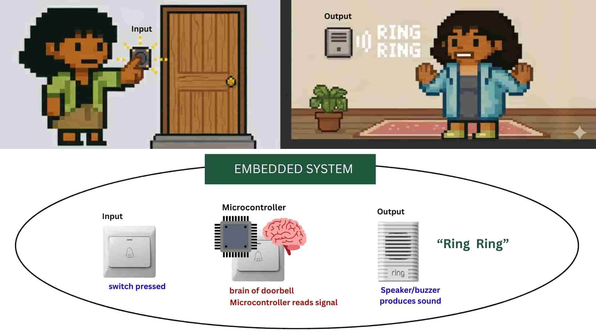
Embedded system:
A dedicated computer system designed to perform a specific task inside a device.
Microcontroller:
The small electronic chip inside an embedded system that acts as the brain, controlling inputs, processing data, and producing outputs. It contains CPU, memory, and input/output pins.
Chatgpt and Gemnini_AI Prompt Used
I used chatgpt to create the prompt to generate image with gemini_banana.
          "Create a retro pixel-art split-scene illustration using the provided pixel characters as the exact reference style, proportions, and color palette.
            Scene composition: The image is divided into two connected halves showing cause and effect.

            Left side (outside the house):
            Use the green-shirt pixel character from the reference. The character is standing in front of a house door and pressing a wall-mounted doorbell button with one raised finger. Show a small pixel glow or click animation around the button to indicate activation. The environment should include a simple pixel house door, minimal porch details, and outdoor lighting consistent with retro game environments.
            Right side (inside the house):

            Use the blue-shirt pixel character from the reference standing inside the house. The character is reacting to the doorbell sound, slightly turning toward a wall-mounted buzzer device. Add pixel sound-wave icons or small 'ring ring' visual indicators near the buzzer to clearly show the ringing effect.
            Style requirements:

            Strictly match the same pixel density, shading style, outlines, and lighting as the provided characters
            Maintain consistent scale and sprite proportions,
            Clean retro game aesthetic
            Clear storytelling showing that pressing the outside button triggers the inside buzzer
            Soft pastel pixel background colors with simple interior/exterior separation using a wall cross-section
            Ensure the characters appear identical to the reference sprites and are not redesigned."

Then using canva, i made the rest of the illustration, sourced the images required from internet.
The whole doorbell device (button, circuit, chip, buzzer) that performs the specific task of producing a sound when pressed -Embedded system.
A tiny chip inside the doorbell, like the doorbell's brain - microcontroller.
Button pressed >> Microcontroller detects signal >> Runs a program ( executes a set of instructions stored in its
memory that tells it what to do when something happens.) >> Microcontroller activates buzzer/ speaker >> Sound produced.
Input device:
information recieved by the microcontroller from the outside devices like button or switch.
Output device:
Device controlled by the microcontroller, the action or signal produced by a system after processing the input.
Getting Started with Seeed Studio XIAO RP2040
Seed Studio: XIAO-RP2040
Seeed Studio XIAO RP2040 is a tiny and compact development board based on the RP2040 chip from Raspberry Pi. It is as as small as a thumb (Dimension: 21x17.8mm) and can be used for wearable devices and small projects. Although the board is small in size, it is powerful and can be programmed using Arduino, MicroPython, and CircuitPython.
Features
Dual-core RP2040 Processor:the brain of the board. It runs the code and tells the board what to do.133MHz:how fast the brain can work.264KB SRAM:the board's short-term memory used while program runs.2MB Flash memory:the board's long-term memory, it stores permanently.Low power:the board can do all this while using less electricity.
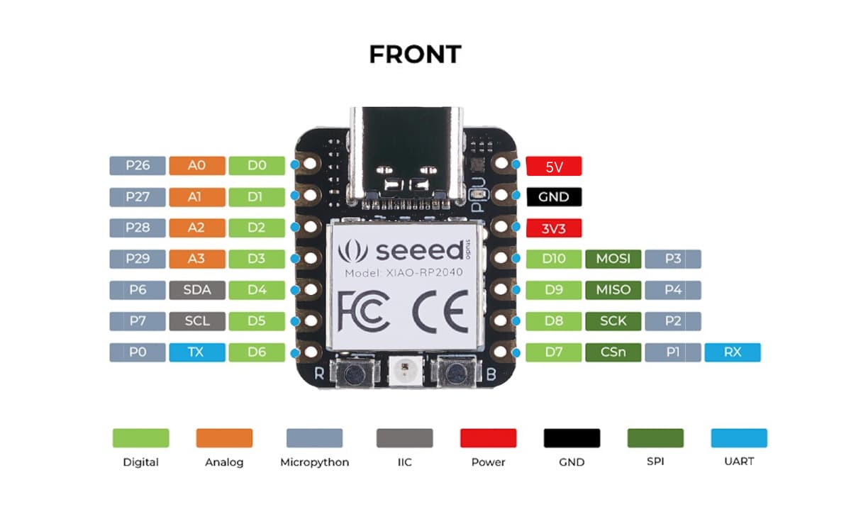
Pinout Mapping
USB Type-C: used to connect the board to the computer for power and uploading code.- Total
14 GPIO pinsare on the xiao RP2040.Out of which11 digital pins: are pins that work with only two states -HIGH/ON/1 or LOW/OFF/0; and4 analog input pins: are used to read changing values, like things in real life - It also supports communication protocols like:
I2C - SDA: D4, SCL: D5

                  SPI - MOSI: D10, MISO: D9, SCK: D8

                  UART - TX: D6, RX: D7
Power Pins
3.3V pin:gives 3.3 volts power to sensors or other boards.5V / VBUS pin:gives 5 volts power from the USB connection.GND pin:means ground
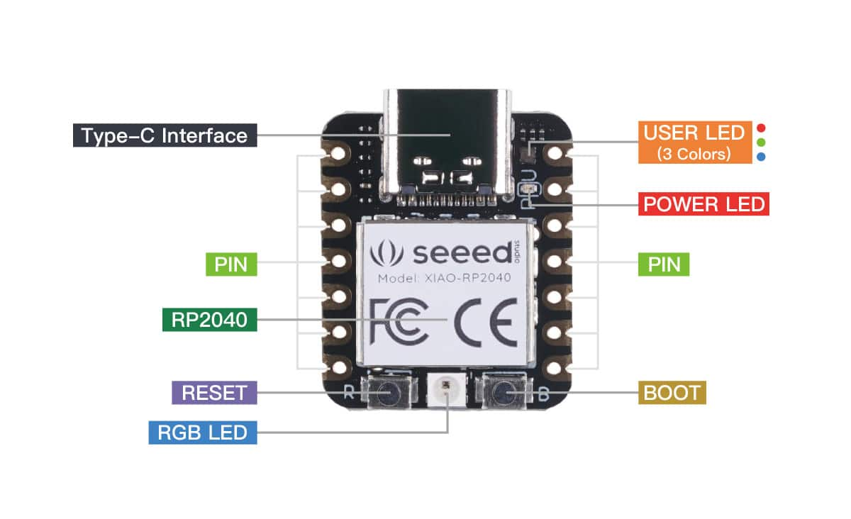
Boot and Reset
Bootloader: to help the computer recognize the board and allow new code to be uploaded to it.Boot Button: used to put the board into bootloader mode for uploading code.Reset Button: used to restart the board and run the program again.
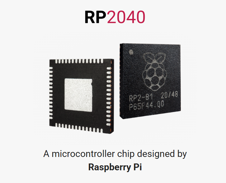
RP2040: A microcontroller chip designed by Raspberry Pi
RP2040 is the microcontroller chip designed to be powerful, low-cost, and easy to use and used in boards like Raspberry Pi Pico and XIAO RP2040.
As it is designed to use low power, it is suitable for small embedded and battery-powered projects.
It has a dual-core Arm Cortex-M0+ processor, which means it has two small processing cores to run code.
It also has a built-in UF2 bootloader, which makes it easy to upload code to the board.
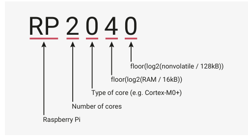
Why is the chip called RP2040?
- RP: Raspberry Pi
- 2: dual-core processor
- 0: Cortex-M0+ core type
- 4: related to the RAM size
- 0: no built-in flash memory on the chip
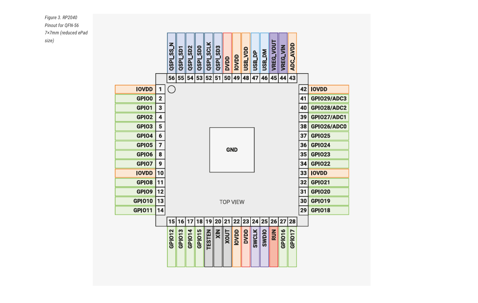
30 GPIO pins, 4 of which can be used as analogue inputs, Peripherals, 2 UARTs, 2 SPI controllers, 2 I2C controllers, 16 PWM channels, USB 1.1 controller and PHY, with host and device support, 8 PIO state machines.
Source: rp2040-datasheet RP2040
BreadBoard and Jumperwires
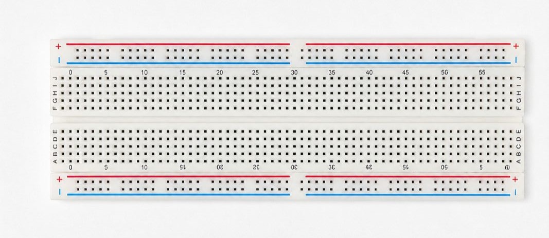
Breadboard:
It is a reusable rectangle board with many holes it in, where you can insert electronic components to make circuits without soldering. Mainly used for prototyping.
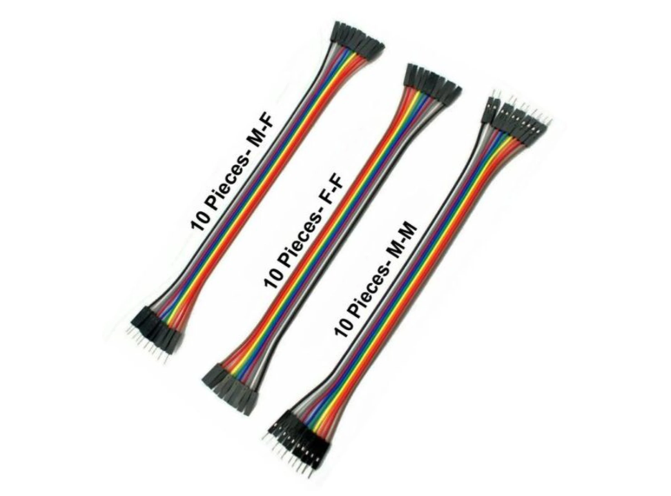
Jumper Wires
It is an electrical wires with connector pins at each end, used to rapidly prototype electronic circuits on breadboards or connect microcontrollers without soldering. Types of jumper wires:
- Male-to-Male: ends having pins.
- Female-to-Female: ends having sockets.
- Female-to-Male: one end with socket and other with pin.
source:jumperwires
Toolchain and Development Workflow: Arduino IDE and Thonny IDE
Toolchain:
Toolchain is a set of software tools used to write, compile, upload, and run a program that work together to convert source code into an executable program for specific hardware.
It usually includes:
- Editor - write the code
- Compiler - convert code to machine code
- Assembler - convert assembly to machine code
- Linker - join all compiled parts
- Uploader - send program to the device
- Debugger / Serial tools - test and debug the program
Arduino IDE
I have used the Arduino IDE earlier, and it is a user-friendly software that allows us
to write and upload code to microcontrollers.
From my previous experience, I knew that when using different boards, it is often necessary to
install the required board packages and set the correct port, as I had faced this issue before.
Earlier, I was not aware of the Additional Board Manager URL concept.
This time, I learned about it in more depth, along with many other tools, shortcuts,
and features available inside the IDE, which helped me better understand how different
third-party boards are supported and configured.
Setting up Arduino IDE
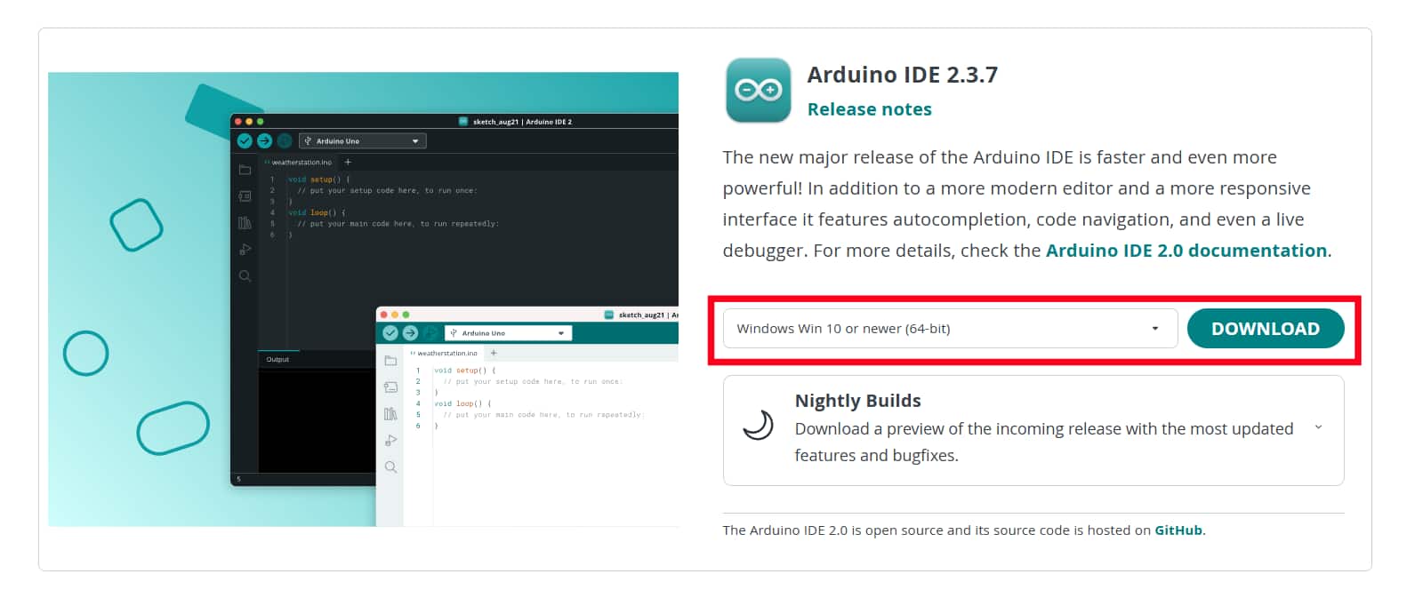
Download and Install the latest version of Arduino IDE according to my operation system(windows), then launch the Arduino application.
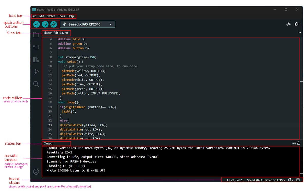
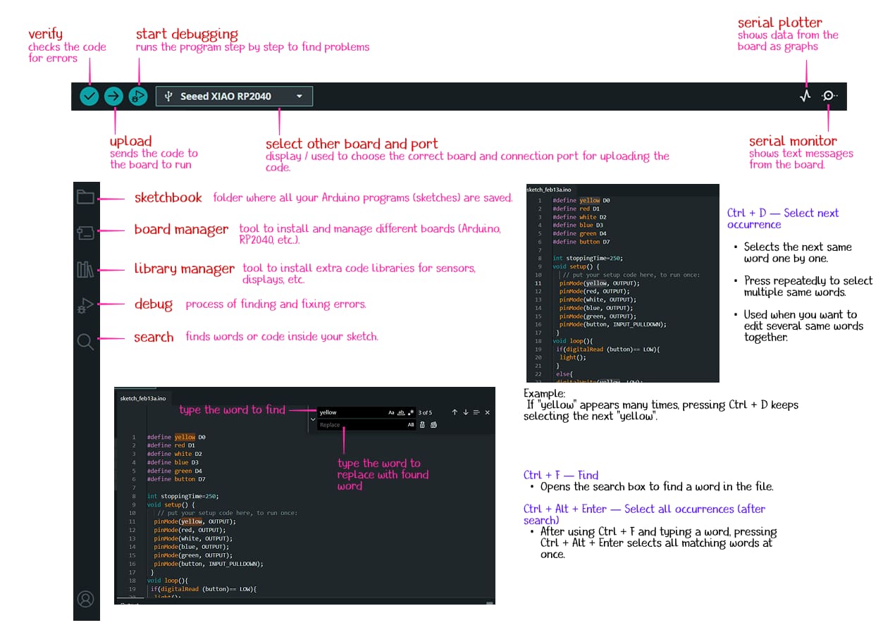
Understanding the code window and tools:
Installing Seeed Studio XIAO RP2040 board package
I followed the instruction provided in seeed studio wiki to connect the Seeed Studio XIAO RP2040 and program with Arduino.
I added the Seeed Studio XIAO RP2040 board package to the Arduino IDE by following these steps.
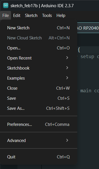
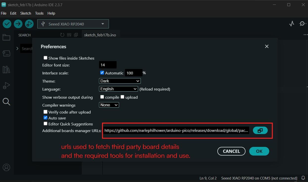
First, I opened File >> Preferences >> pasted the provided link in the Additional Boards Manager URLs clipboard.
This step was necessary because the Arduino IDE does not originally contain files for third-party boards like Seeed Studio.
url:
https://github.com/earlephilhower/arduino-pico/releases/download/global/package_rp2040_index.json
The URL to a JSON file that provides the board definition, required drivers, and toolchain settings, and also tells the IDE which boards are available and which compiler/tools need to be downloaded.
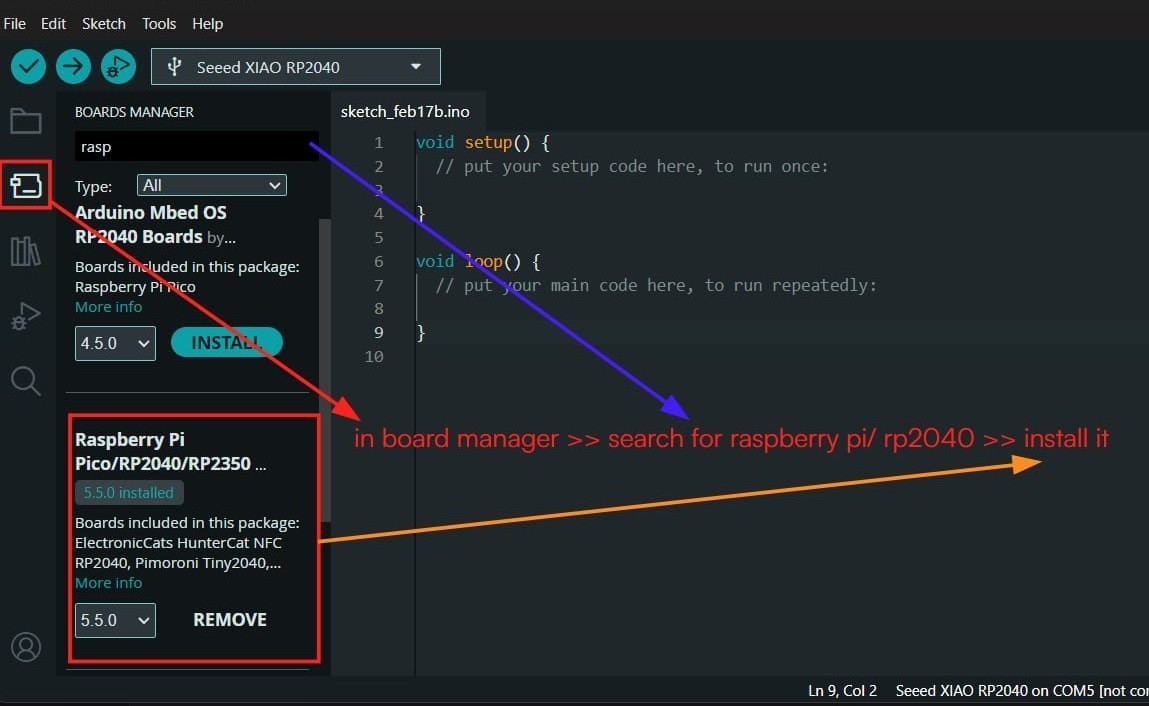
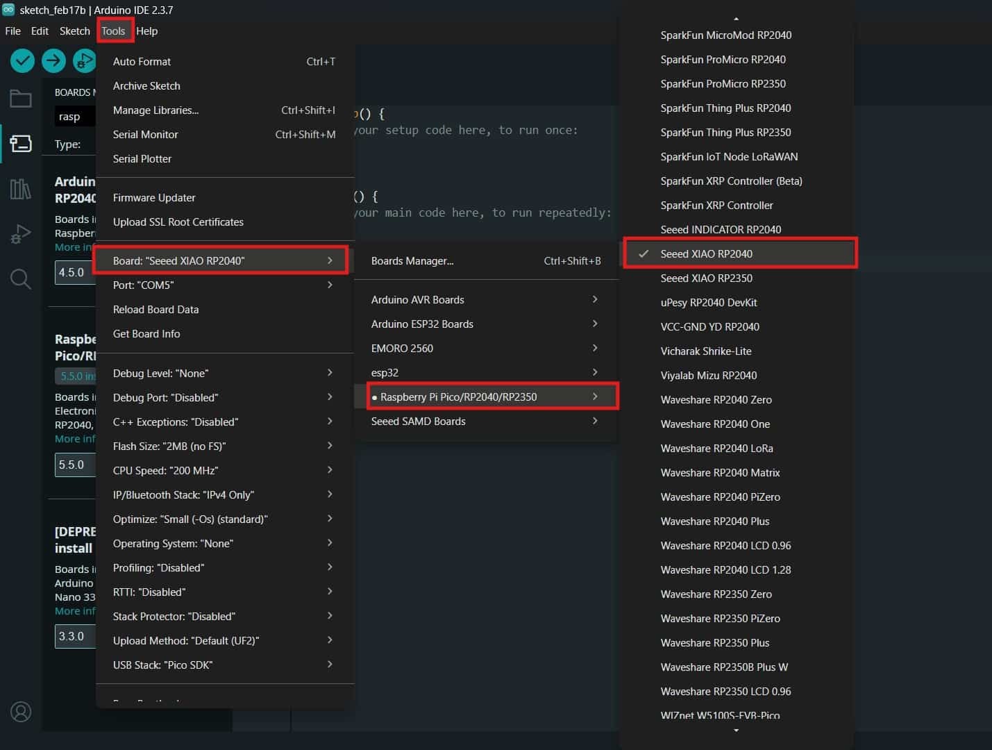
After adding the URL, Boards Manager >> searched for "Raspberry Pi Pico/RP2040", and installed the package. This package includes support for the Seeed Studio XIAO RP2040 board, Tools >> Board >> selected the required board from the board list.
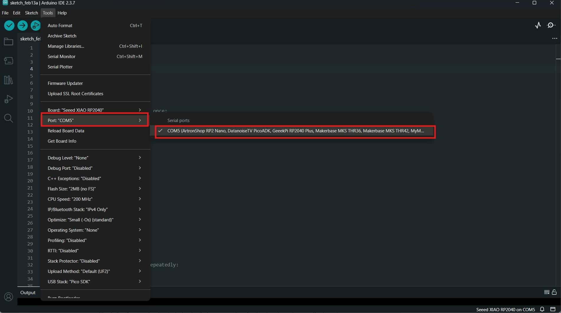
Next, I connected the Seeed Studio XIAO RP2040 board to my computer (c-type - USB cable).
While connecting the board for the first time, I held the BOOT button and plugged it into the computer so the system could detect it properly.
Then, Tools >> Port and selected the correct port to which the board was connected.
Learning basic codes and logics
Whenever you open new sketches, it defaults has basic template with two main functions: setup() and loop().
                    void setup() {
                        // put your setup code here, to run once:

                    }

                    void loop() {
                        // put your main code here, to run repeatedly:

                    }
Comment(// or */)
the feature used to add human-readable notes within the source code.
Basically you comment out (ctrl + /) lines of code that you don't want to run or add explanatory notes.
// for one line comment

                     /* for multi-line comment */
#define
Used to assign a name to a constant value before the program compiles. No memory used
int
Used to declare an integer variable in the program. Memory used and value can be changed during execution.
                  #define ledPin D0 /* Defines/assigns that the LED is connected to pin D0.
                                      Wherever the compiler sees ledPin in the code,
                                      it replaces it with D0. */
                   int ledPin = D0; /* creates a variable named ledPin and assigns
                                    it the value D0.*/
pinMode()
Used to set the pin as INPUT or OUTPUT.
digitalWrite()
Used to turn a device ON or OFF. By setting the value HIGH or LOW.
                 #define ledPin D3 // Defines/assigns that the LED is connected to pin D3.
                 int delayTime = 200; /* creates a variable named delayTime and assigns
                                        it the value 200 ms. */
                 void setup() {
                 pinMode(ledPin, OUTPUT); // sets the ledPin as an output pin.
                }
                void loop() {
                digitalWrite(ledPin, HIGH); // turns on the LED by setting the ledPin to HIGH.
                delay(delayTime); /* waits for the specified delay time (200 ms)
                                     before proceeding to the next instruction. */
                digitalWrite(ledPin, LOW); // turns off the LED by setting the ledPin to LOW.
                delay(delayTime);
                }
Programming: Blink Example Code
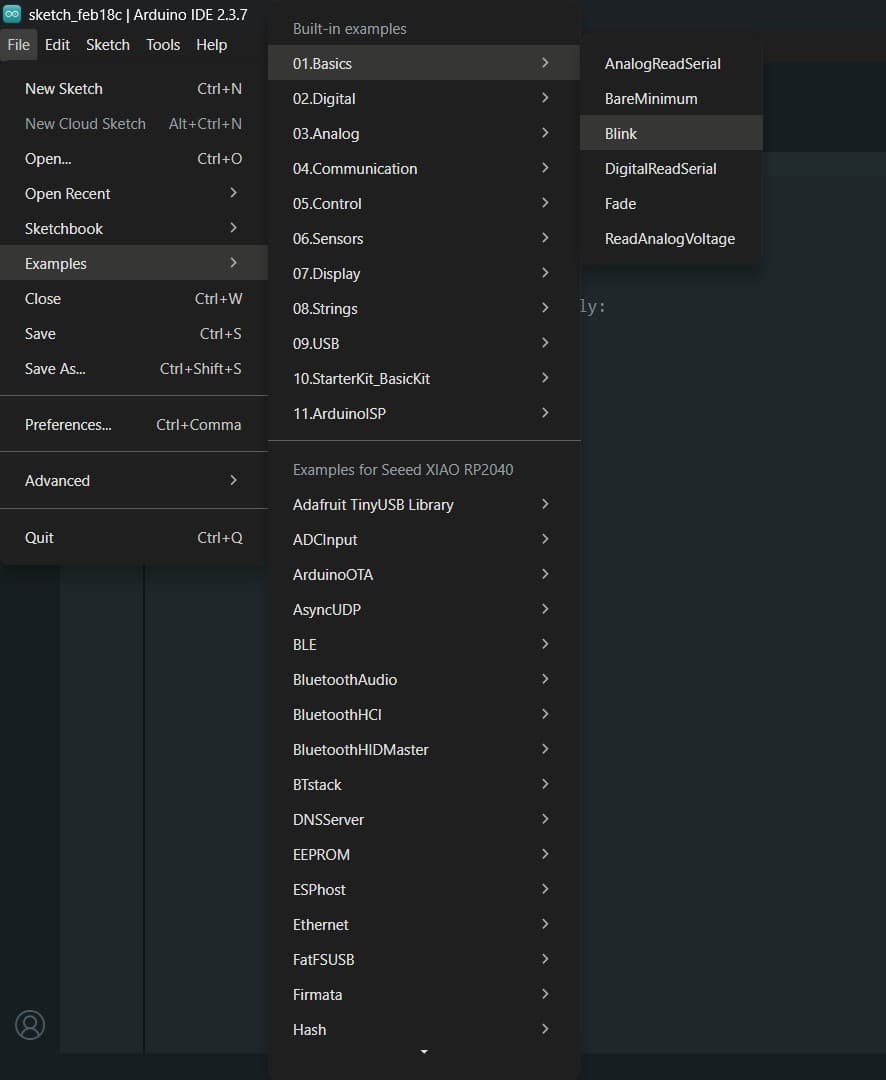
To test the board and my setup, I opened the Blink example code from File >> Examples >> Basics >> Blink.
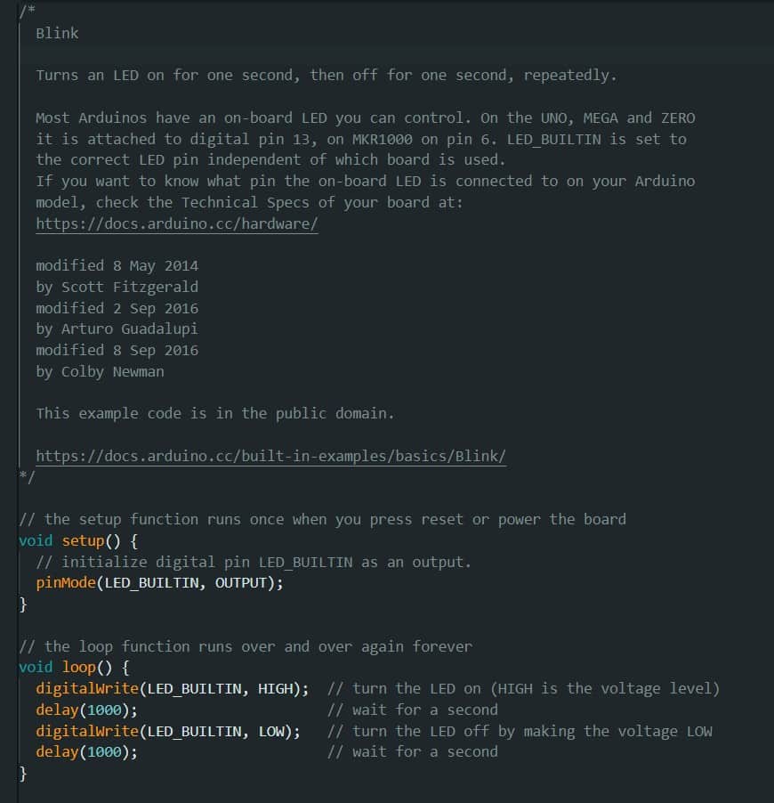
         // the setup function runs once when you press reset or power the board
        void setup() {
          // initialize digital pin LED_BUILTIN as an output.
          pinMode(LED_BUILTIN, OUTPUT);
        }

        // the loop function runs over and over again forever
        void loop() {
          digitalWrite(LED_BUILTIN, HIGH);  // turn the LED on (HIGH is the voltage level)
          delay(1000);                      // wait for a second
          digitalWrite(LED_BUILTIN, LOW);   // turn the LED off by making the voltage LOW
          delay(1000);                      // wait for a second
        }
In the Blink example, the constant LED_BUILTIN did not work with the XIAO RP2040 because this board does not use the same built-in LED pin definition as some Arduino boards. By checking the XIAO RP2040 pin-mapping in the Seeed Studio wiki, I found that the onboard RGB LEDs are instead:
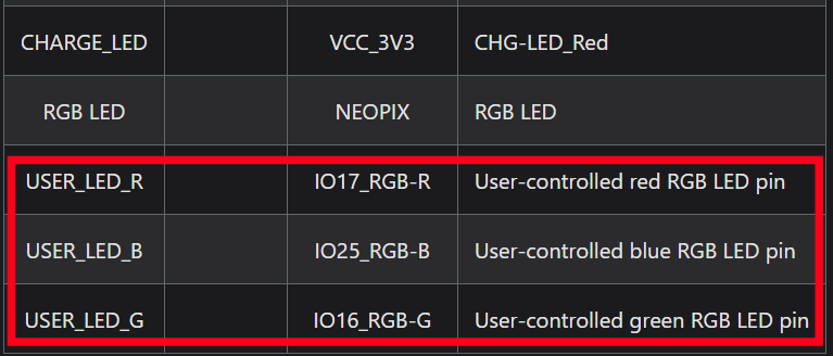
I modified the Blink code to use USER_LED_B (GPIO 25), which is the blue LED on the XIAO RP2040.
I learned a new concept,While debugging why the LED behavior was different from the usual HIGH = ON logic.
The onboard RGB LED on the XIAO RP2040 is a Common Anode (Anodic type) LED.
This means the anode (+) is connected to 3.3V, and the GPIO pin controls the cathode (-).
Because of this wiring, the logic works in the opposite way: LOW = ON; HIGH = OFF.
So the LED turns on when the pin is set to LOW and turns off when it is set to HIGH, and it worked successfully.
        #define USER_LED_B 25 // Defines/assigns that the blue LED is connected to pin 25.
         // the setup function runs once when you press reset or power the board
        void setup() {
          // initialize digital pin USER_LED_B as an output.
          pinMode(USER_LED_B, OUTPUT);
        }

        // the loop function runs over and over again forever
        void loop() {
          digitalWrite(USER_LED_B, LOW);  // turn the LED on by setting the voltage LOW (active LOW)
          delay(1000);                      // wait for a second
          digitalWrite(USER_LED_B, HIGH);   // turn the LED off by making the voltage HIGH
          delay(1000);                      // wait for a second
        }
After that, i noticed that other LEDs are on by default when the board is powered on. i modified the code to turn off the red and blue LEDs by setting them to HIGH in the setup function, and then blink the green LED twice by setting it to LOW and HIGH with a delay in between.
        #define USER_LED_R 17
        #define USER_LED_G 16
        #define USER_LED_B 25
        // define RGB LED pins according to the XIAO RP2040 pin mapping.
        int lowdelay =100; // delay time for LED ON state
        int highdelay = 300; // delay time for LED OFF state
        void setup() {
          // Configure RGB LED pins as output
          pinMode(USER_LED_R, OUTPUT); // sets the red LED pin as output.
          pinMode(USER_LED_G, OUTPUT);
          pinMode(USER_LED_B, OUTPUT);


          digitalWrite(USER_LED_R, HIGH);
          digitalWrite(USER_LED_B, HIGH);
        }

        void loop() {
          // Blink red LED twice

          digitalWrite(USER_LED_G, LOW);   // ON (active LOW)
          delay(lowdelay);
          digitalWrite(USER_LED_G, HIGH);  // OFF
          delay(highdelay);

          digitalWrite(USER_LED_G, LOW);   // ON
          delay(lowdelay);
          digitalWrite(USER_LED_G, HIGH);  // OFF
          delay(highdelay);
        }
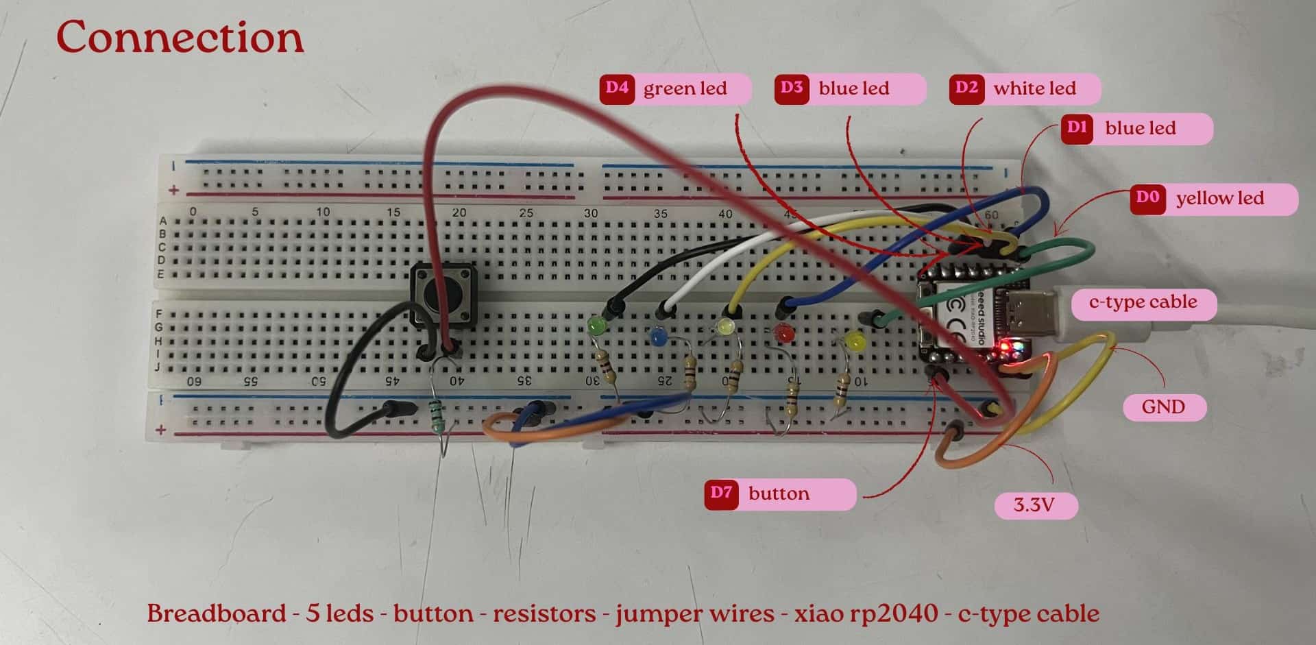
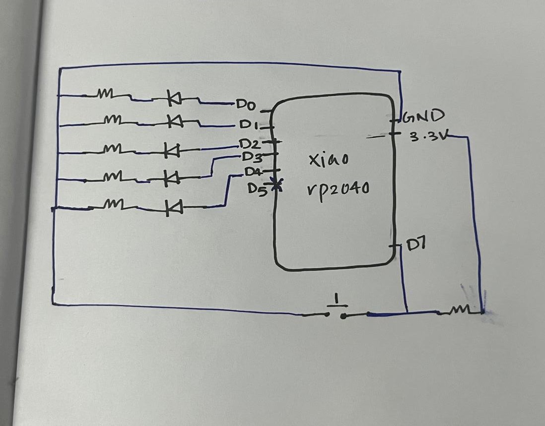
Using a breadboard and external components: leds, button, resistors, jumper wires; I built an LED chase circuit controlled by a button. I used an if-else statement and a user-defined function to execute the LED sequence.
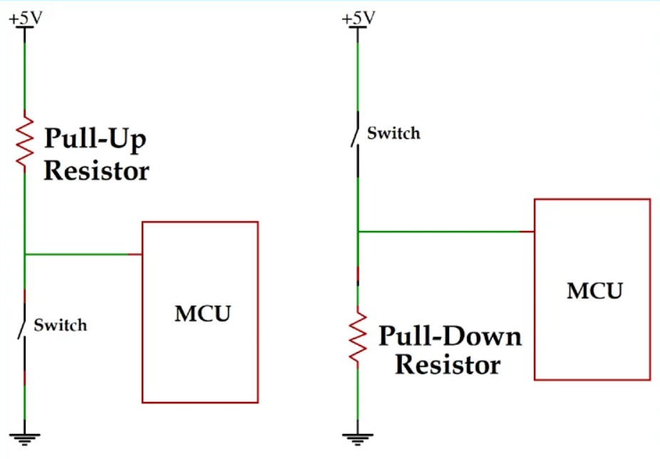
Pull-up and Pull-down resistor
source:pull-up-and-pull-down-resistor
Pull-up and pull-down resistors are used to keep a digital input pin at a fixed HIGH or LOW state when no signal is given, so it does not float and give random values. Which one to use?
Use pull-up resistor when:
- you want the pin to stay HIGH by default
- pressing the switch connects the pin to GND
- output becomes LOW when pressed
Use pull-down resistor when:
- you want the pin to stay LOW by default
- pressing the switch connects the pin to VCC
- output becomes HIGH when pressed
if-else
if-else statement is used for decision making in a program.
It tells the microcontroller:
“If this condition is true, do this”;
“Otherwise, do something else.”
if-else statement inside the loop function, the microcontroller keeps checking the condition repeatedly.
      void loop(){ // put code here, to run repeatedly:
      if(digitalRead (button)== LOW){ /* checks the button state. If the state is LOW
                                      (button is pressed), the condition becomes true */
      light(); /* calls the light function to execute the LED sequence when
                  the button is pressed. */
      }
      else{ /* If the button is not pressed, all the LEDs are turned off by setting
              led's state to LOW. */
      digitalWrite(yellow, LOW);
       }
      }
void functionName()
A user-defined function is a block of code created by the programmer to perform a specific task.
Once the function is created, can call it from anywhere in the program (after it is defined)
by writing its name with parentheses, like light();.
This makes the code cleaner, more organized, and easier to understand.
Here in this program, instead of writing the LED sequence inside loop() again and again,
I created a separate function called
void light() When the button is pressed,
the program calls light();
            #define yellow D0 // Defines/assigns that the yellow LED is connected to pin D0.
            #define red D1
            #define white D2
            #define blue D3
            #define green D4
            #define button D7

            int stoppingTime=250; /* creates a variable storing 250 milliseconds
                                    delay between LED switching. */

            void setup() { // put setup code here, to run once:
              pinMode(yellow, OUTPUT); // sets the yellow LED pin as output.
              pinMode(red, OUTPUT);
              pinMode(white, OUTPUT);
              pinMode(blue, OUTPUT);
              pinMode(green, OUTPUT);
              pinMode(button, INPUT);
            }

            void loop(){ // put code here, to run repeatedly:
            if(digitalRead (button)== LOW){ /* checks the button state. If the state is LOW
                                            (button is pressed), the condition becomes true */
              light(); /* calls the light function to execute the LED sequence when
                          the button is pressed. */
            }
            else{ /* If the button is not pressed, all the LEDs are turned off by setting
                     led's state to LOW. */
            digitalWrite(yellow, LOW);
            digitalWrite(red, LOW);
            digitalWrite(white, LOW);
            digitalWrite(blue, LOW);
            digitalWrite(green, LOW);
            }
            }

            void light() { /* user-defined function to execute the LED sequence
                              when the button is pressed. */
            digitalWrite(yellow, HIGH); // turns on the yellow LED
            delay(stoppingTime); /* waits for the specified stopping time (250 ms)
                                    before proceeding to the next instruction. */
            digitalWrite(yellow, LOW); // turns off the yellow LED

            digitalWrite(red, HIGH);
            delay(stoppingTime);
            digitalWrite(red, LOW);

            digitalWrite(white, HIGH);
            delay(stoppingTime);
            digitalWrite(white, LOW);

            digitalWrite(blue, HIGH);
            delay(stoppingTime);
            digitalWrite(blue, LOW);

            digitalWrite(green, HIGH);
            delay(stoppingTime);
            digitalWrite(green, LOW);
            }
I first used Chatgpt_AIto generate the program through prompting, but the output was not exactly what I expected.
With my instructor's guidance, we iterated and refined the code step by step until it worked correctly.
Through this process, I learned new concepts, codes.
Also i didn't have the prompt for this code, i lost this chat with ai.
The final program allows a button press to toggle ( Button toggle means changing the state from ON to OFF or OFF to ON using one button.)
multiple LEDs blinking on and off while displaying the current status in the Serial Monitor.
Bool
A boolean is a data type that can store only two values:true, false.
In Arduino, it can also be: HIGH (1), LOW (0). Like button pressed/ not pressed; Led ON/OFF.
bool blinkState = false; // creates a toggle switch that starts in the OFF position.
    /* When i first plug in Arduino, i don't want the lights to start blinking immediately.
       By setting it to false, telling the code,
      "Wait for me to press the button before starting the blinking logic."*/
    // bool:true (ON) or false (OFF).
    //late in the code, inside:
    void loop(){
  if (currentButton == HIGH && lastButtonState == LOW) {
    blinkState = !blinkState; //! means "NOT"
    /* first pressed: blinkState becomes NOT false (True). The blinking starts
       Again pressed: blinkState becomes NOT true (False). The blinking stops. */
   }
  }
long
Long is a data type in Arduino that can store large integer values. Here i used to store time values returned by the millis(1sec= 1000ms).
 long tim =0; /* means create a variable named lastTime of type long and
                assign it an initial value of 0, sets its starting value to zero.*/
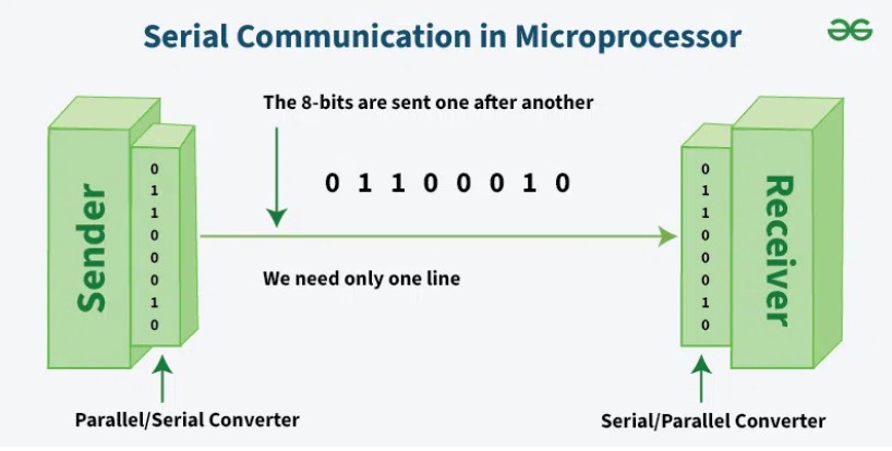
serial
communciation

Source: serialvsparallel stringtelephone
Serial communication is like a string telephone: two people, 2 cups and a string connecting them—
one talks >> passes the information >> the other listens, and they take turns using the same single path.
It is a way of sending data, one bit at a time, over a single communication line between two devices.
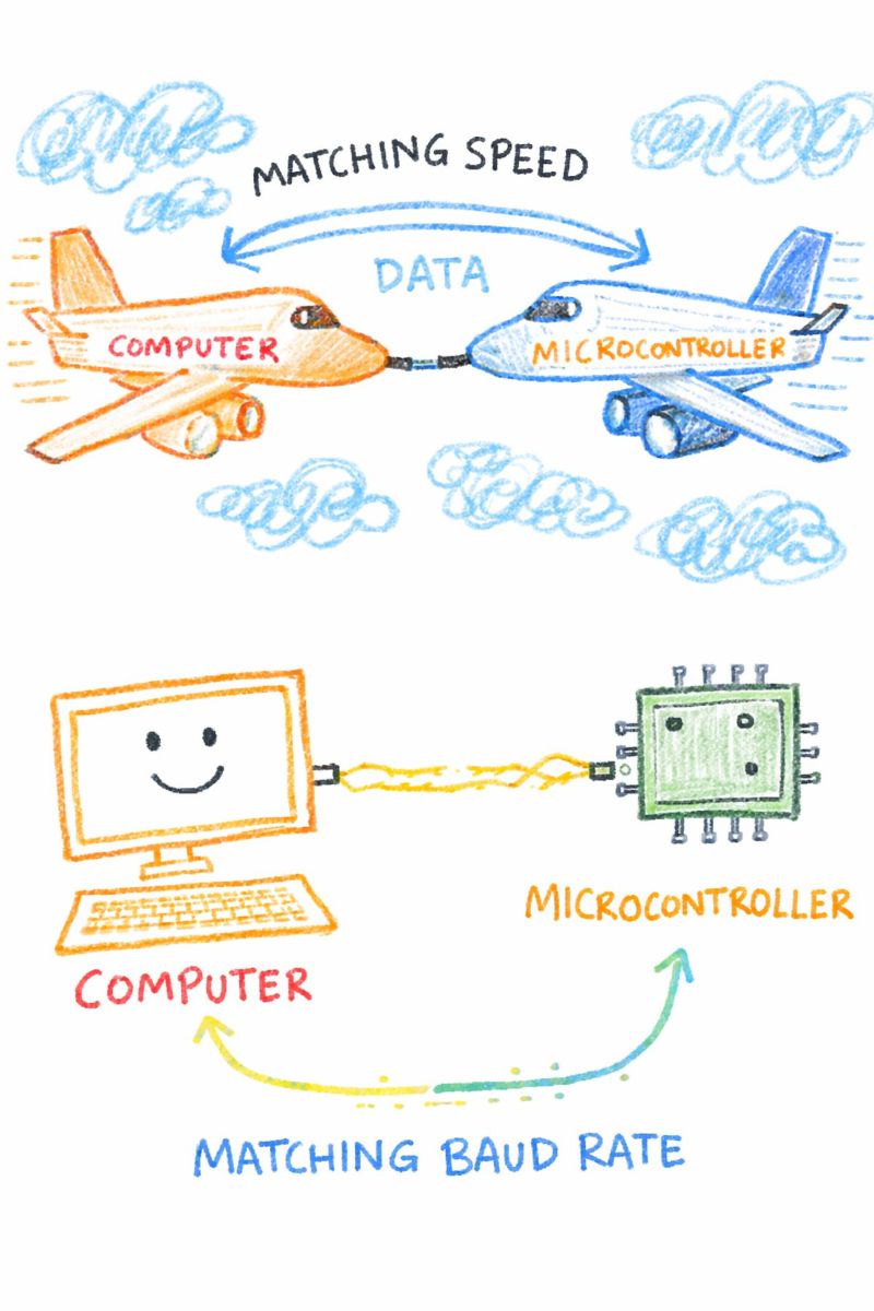
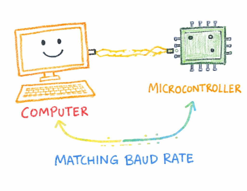
Baud rate
The speed of data transmission in serial communication, measured in bits per second (bps).
Common baud rates include 9600, 115200, etc. Both the sender and receiver must use the same baud rate
for successful communication.
To understand this concept, our instructor explained baud rate in a really cool way that honestly
made it impossible to forget. He told us to imagine a fighter jet refuelling a Boeing aeroplane
in mid-air.

Chatgpt and Gemini_AI Prompt Used
            Our instructor explained baud rate in a really cool way that honestly made it impossible to forget.
             He told us to imagine a fighter jet refuelling a Boeing aeroplane in mid-air.
             For that to work, both aircraft must fly at the same speed and direction.
             If one is faster or slower, the connection becomes unstable, and the whole operation can fail.
              Then he said, “Now imagine one plane is the computer and the other is the microcontroller, and the fuel being transferred is your data.”
              Just like those planes must match speeds accurately, the computer and microcontroller must be set to the same baud rate to communicate properly.
              If the speeds don't match, the data gets messed up — not an explosion like in the sky,
              but definitely, communication is corrupted.
               That analogy honestly made baud rate feel less like some boring technical term that
                I have to memorise for now and then forget later, next time, instead of thinking “ what is baud rate? ”I just think of two planes matching speed,
                meaning both devices must communicate at the same speed. generate a line drawing like kid for visualing the concept sketch those planes, comp, microcontroller.
                in simplest form ever.
Reference image i gave to gemini


Source: aerial refueling Kuba Dyc
Gemnini_generated_img


Then again iterated with chatgpt:
After few iterations i got almost similiar one i imagined.

Later using chatgpt, prompt: i want a person thinking with a thought bubble above them with reference image inside in it.
Below the illustration, include the caption: “Baud rate? It's just like two planes matching speed”.
Later i asked it to change the person to the character i gave.
Then he said, “Now imagine one plane is the computer and the other is the microcontroller, and the fuel being transferred is your data.”
 Just like those planes must match speeds accurately, the computer and microcontroller
must be set to the same baud rate to communicate properly.
If the speeds don't match, the data gets messed up — not an explosion like in the sky,
but definitely, communication is corrupted.
Just like those planes must match speeds accurately, the computer and microcontroller
must be set to the same baud rate to communicate properly.
If the speeds don't match, the data gets messed up — not an explosion like in the sky,
but definitely, communication is corrupted.  That analogy made baud rate feel less like some boring technical term that I have
to memorise for now and then forget later, next time, instead of thinking
“ what is baud rate? ”I just think of two planes matching speed, meaning both devices
must communicate at the same speed.
That analogy made baud rate feel less like some boring technical term that I have
to memorise for now and then forget later, next time, instead of thinking
“ what is baud rate? ”I just think of two planes matching speed, meaning both devices
must communicate at the same speed.
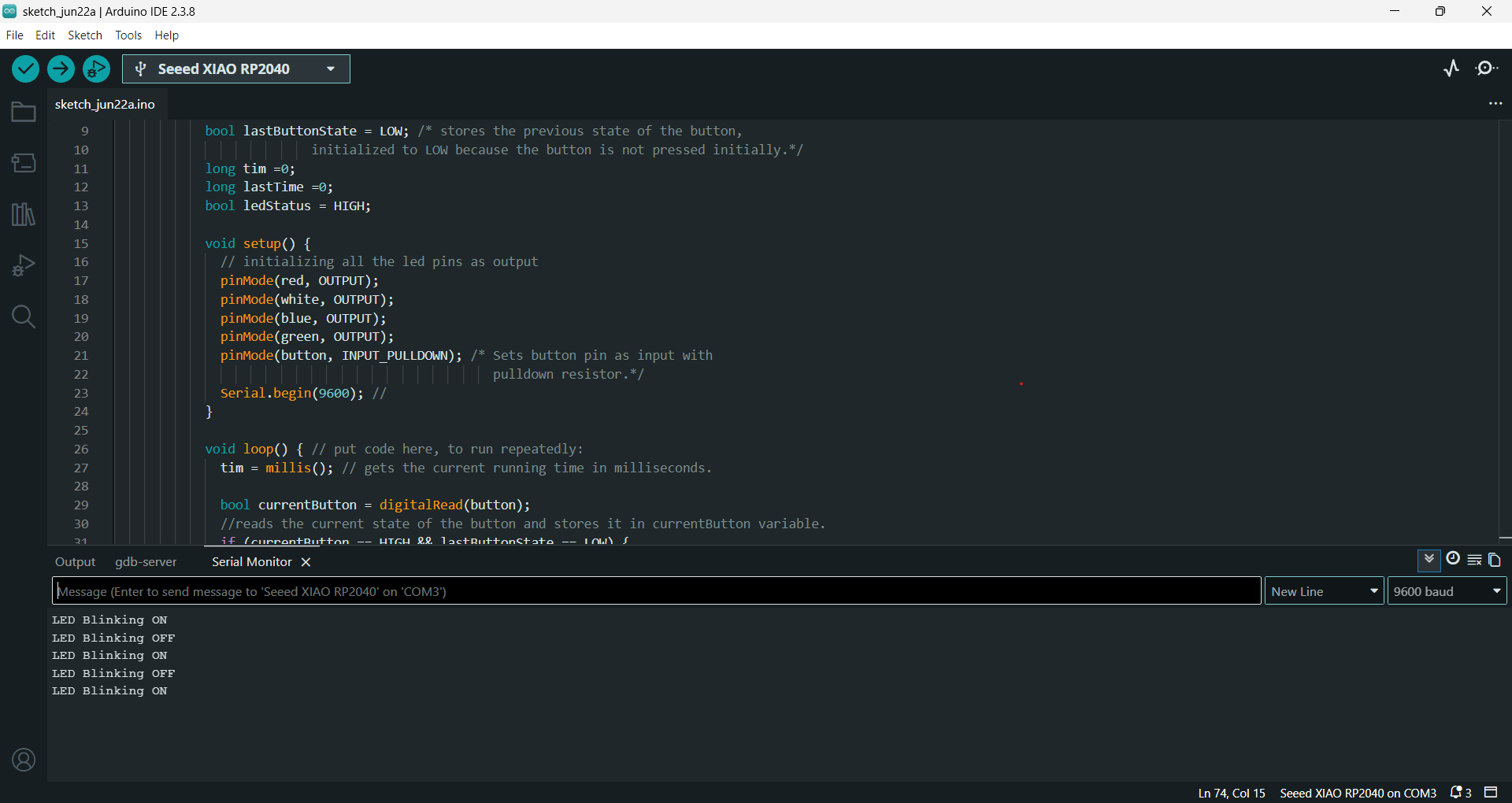
Serial.begin(9600)
Used to initialize the serial communication between the microcontroller and the computer.
Start sending data to the computer using serial communication at 9600 bits per second, and
the serial monitor must match this speed.
Must start the communication
first, using Serial.begin() before using Serial.print() or Serial.println(). Otherwise, nothing will be displayed.
Serial Monitor
A tool in the Arduino IDE that lets you see messages sent from your board to your computer.
Serial.print()
It prints the data on the same line in the serial monitor.
Serial.print("LED Blinking ON"); /*Prints message to the serial monitor
                                                       if blinking is ON.*/
Serial.print("LED Blinking OFF"); /*prints message to the serial monitor
                                                       if blinking is OFF.*/
/* in serial monitor, it will show:
LED Blinking ONLED Blinking OFF */
Serial.println()
It prints the data and moves the cursor to the next line in the serial monitor.
Serial.println("LED Blinking ON"); /*Prints message to the serial monitor
                                                     if blinking is ON.*/
Serial.println("LED Blinking OFF"); /*prints message to the serial monitor
                                                     if blinking is OFF.*/
/* in serial monitor, it will show:
LED Blinking ON
LED Blinking OFF */
            #define red   D1 // Defines/assigns that the red LED is connected to pin D1.
            #define white D2
            #define blue  D3
            #define green D4
            #define button D7

            bool blinkState = false; // creates a toggle switch that starts as OFF state.
            bool lastButtonState = LOW; /* stores the previous state of the button,
                          initialized to LOW because the button is not pressed initially.*/
            long tim =0;
            long lastTime =0;
            bool ledStatus = HIGH;

            void setup() {
              // initializing all the led pins as output
              pinMode(red, OUTPUT);
              pinMode(white, OUTPUT);
              pinMode(blue, OUTPUT);
              pinMode(green, OUTPUT);
              pinMode(button, INPUT_PULLDOWN); /* Sets button pin as input with
                                                  pulldown resistor.*/
              Serial.begin(9600); //
            }

            void loop() { // put code here, to run repeatedly:
              tim = millis(); // gets the current running time in milliseconds.

              bool currentButton = digitalRead(button);
              //reads the current state of the button and stores it in currentButton variable.
              if (currentButton == HIGH && lastButtonState == LOW) {
                /* checks if the button is pressed right now (HIGH) and it was not
                pressed before (LOW) which means the button was just pressed.*/
                blinkState = !blinkState;
                //Toggles blinking state between ON and OFF each time the button is pressed.

                if (blinkState)
                  Serial.println("LED Blinking ON"); /*Prints message to the serial monitor
                                                       if blinking is ON.*/
                else
                  Serial.println("LED Blinking OFF"); /*prints message to the serial monitor
                                                         if blinking is OFF.*/
                delay(200); // Small delay to prevent multiple detections (debouncing).
              }

              lastButtonState = currentButton;
              // Updates lastButtonState to the current state for the next loop iteration.
              if (blinkState) { // If blinking is enabled.
                if(tim-lastTime >= 300)
                // checks if 300 milliseconds have passed since the last toggle of the LEDs.
                {
                digitalWrite(red, ledStatus);
                digitalWrite(white, ledStatus);
                digitalWrite(blue, ledStatus);
                digitalWrite(green, ledStatus);
                // sets the state of all LEDs to the current ledStatus (HIGH = ON).
                ledStatus = !ledStatus;
                // Toggles ledStatus for the next blink (ON to OFF, OFF to ON).
                lastTime =tim;
                // Updates lastTime to the current time after toggling the LEDs.

                }

              }
             else
              {
                ledStatus =LOW;// set the ledstate to low which ensure all LEDs are turned off.
                digitalWrite(red, ledStatus);
                digitalWrite(white, ledStatus);
                digitalWrite(blue, ledStatus);
                digitalWrite(green, ledStatus);
              }
            }
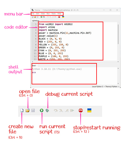
Thonny IDE
Thonny IDE is a simple and beginner-friendly Python IDE that is also suitable for embedded programming. It allows you to write and upload code to microcontrollers, especially those that support Python programming.
I followed the instruction provided in Seed studio wiki: Seeed Studio XIAO RP2040 with MicroPython for installing thonny ide. They also provide example codes to test with, followed same instructions and example code.
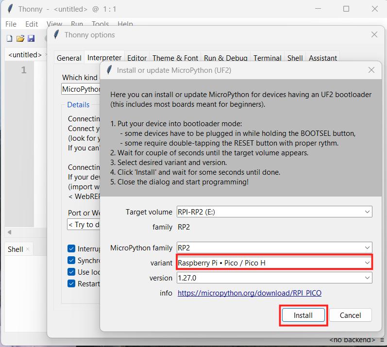
Software setup
- Open Thonny and go to Tools >> Options >> Interpreter.
- Select MicroPython (Raspberry Pi Pico) and choose the port as Try to detect port automatically.
- Press and hold the BOOT button on the XIAO RP2040, then connect it to the computer using a Type-C cable, the board will appear as RPI-RP2 on the computer..
- In thonny ide, Tools >> Options >> Interpreter >> click Install or update MicroPython and keep the default version to install it on the board.
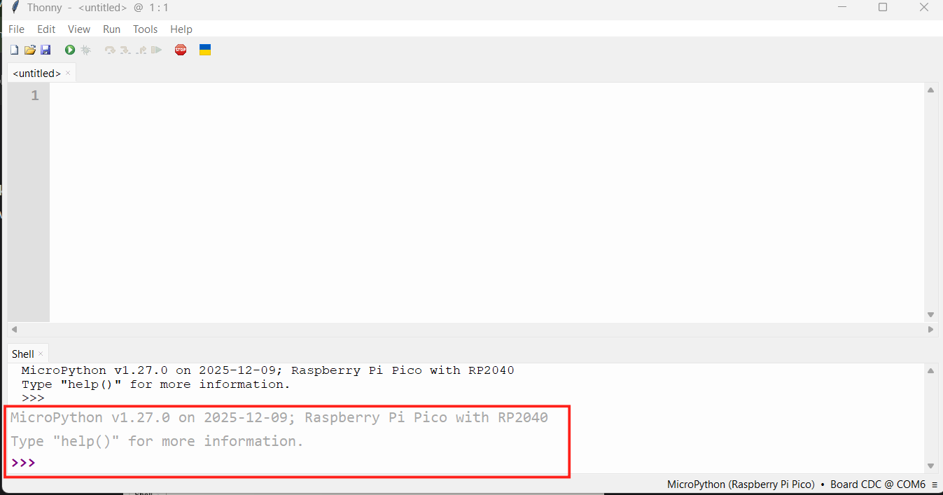
Connect Seeed Studio XIAO RP2040 to the PC and Light it up
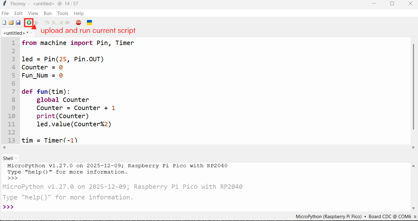
from machine import Pin, Timer
//Import Pin for controlling GPIO pins and Timer for repeated timing actions
led = Pin(25, Pin.OUT) // Set GPIO 25 as an output pin(in-built led)
Counter = 0 // Variable to store how many times the timer has run
Fun_Num = 0
def fun(tim): //Function that runs every time the timer triggers
global Counter //Use the global Counter variable inside the function
Counter = Counter + 1 //Increase the counter by 1
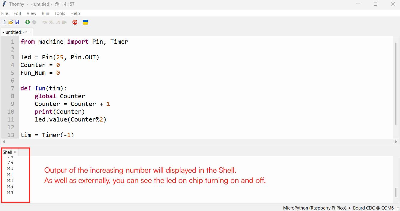
print(Counter) //Print the counter value in the serial monitor
led.value(Counter%2) //Turn LED ON and OFF repeatedly
tim = Timer(-1) // Create a timer
tim.init(period=1000, mode=Timer.PERIODIC, callback=fun)
//Run the function every 1000 ms (1 second)
Light up RGB LED on the Seeed Studio XIAO RP2040
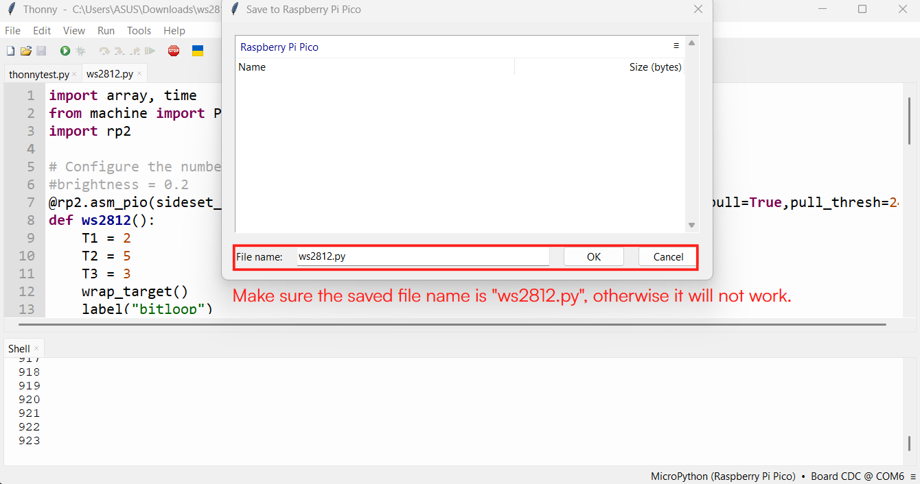
ws2812.py library
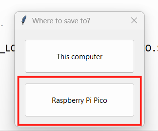
- Download the ws2812.py library and open it with Thonny.
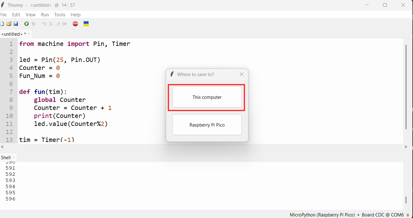
- "File >> Save as" and save the library.
- Save to Raspberry Pi Pico
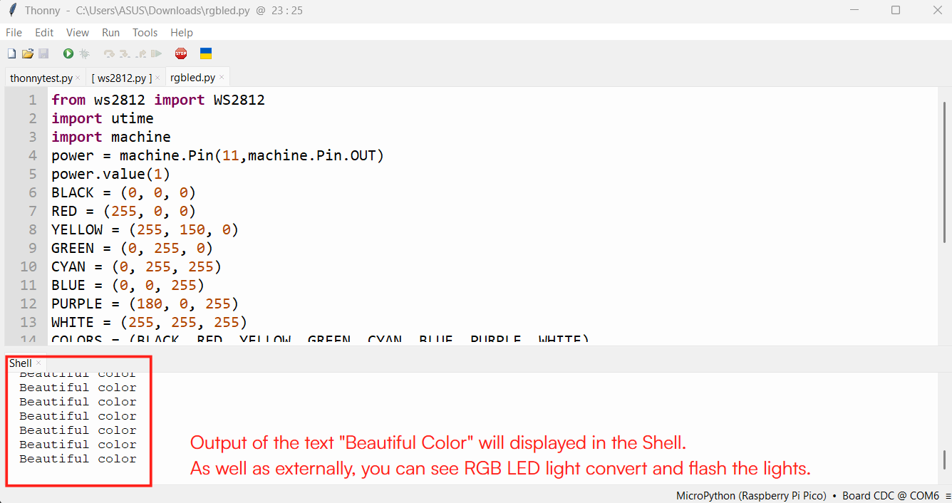
            from ws2812 import WS2812 //Import WS2812 LED library
            import utime  //Import time module for delay
            import machine //Import machine module for pin control
            power = machine.Pin(11,machine.Pin.OUT)
            //Set pin 11 as output to control power
            power.value(1) //Turn ON power to the LED

            BLACK = (0, 0, 0)
            RED = (255, 0, 0)
            YELLOW = (255, 150, 0)
            GREEN = (0, 255, 0)
            CYAN = (0, 255, 255)
            BLUE = (0, 0, 255)
            PURPLE = (180, 0, 255)
            WHITE = (255, 255, 255)
            COLORS = (BLACK, RED, YELLOW, GREEN, CYAN, BLUE, PURPLE, WHITE)
            //Store all colors in one list
            led = WS2812(12,1)#WS2812(pin_num,led_count)
           // Connect WS2812 LED on pin 12, with 1 LED

            while True: //Run forever
                print("Beautiful color")
                //prints the text Beautiful color in the shell output
                for color in COLORS: //Go through each color one by one
                    led.pixels_fill(color) //Fill the LED with the selected color
                    led.pixels_show() //Show the color on the LED
                    utime.sleep(0.2)  //Wait for 0.2 seconds before changing color
My Experience with Arduino IDE and Thonny
I found Arduino IDE more user-friendly and easier to use, probably because I had used it before
and was already familiar with its interface and workflow.
So my preference may also be a little biased by that prior experience.
Thonny was useful for working with MicroPython, and I mainly followed the Seeed Studio documentation
for setting up the XIAO RP2040 with MicroPython.
Since I did not explore Thonny much beyond that workflow,
I felt more comfortable with Arduino IDE overall.