Understand what can go wrong, how to handle it, and how to avoid unsafe situations.
Stay Attentive
Never leave a machine unattended while it is running.
Fire Safety
If a fire occurs during laser cutting, pause the machine or use the emergency stop before opening the lid.
Use the Right Materials
Ensure the material is suitable for the machine. Avoid cutting PVC or ABS on the laser cutter.
Ventilation
Always keep the exhaust system ON while operating machines.
PPE
Wear appropriate safety equipment such as masks, gloves, and goggles.
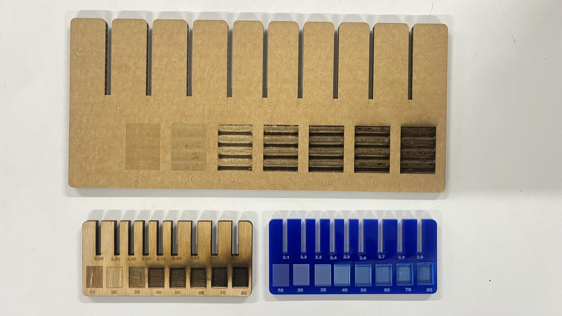
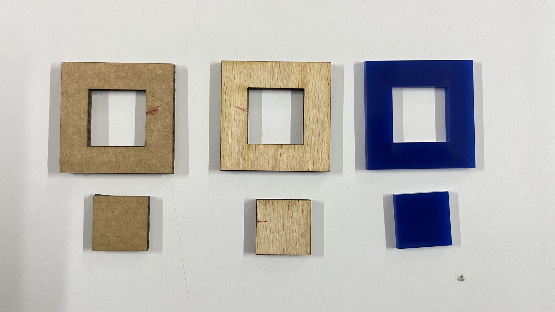
As it is a group assignment, our instructor made us all try designing a parametric test
jig sketch in Fusion 360 individually, so that we can understand how to adjust slot
dimensions parametrically and test different fitting tolerances. As the result of test we found value of kerf, press fit, material thickness.
Kerf
refers to the amount of material that is removed by the laser beam during the Laser cutting process.
Kerf values we got from test are :
Carboard: 0.3mm
Wood: 0.14mm
Acrylic: 0.1mm
Press fit
For getting tight-fit joints, we need to know the compression or press-fit tolerance of the materials.
By adjusting the slot width based on the compression value, we can achieve joints that fit tightly.
Press-fit clearance: 0.2mm
Individual Assignments
Computer Controlled Cutting - using machines that follows x and y coordinates to cut or engrave materials.
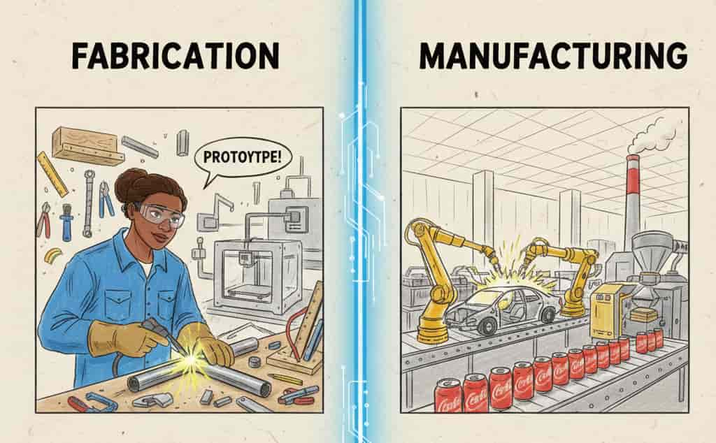
Before starting with CAM, i think we need to be clear with what is the difference between fabrication and Manufacturing, it was pretty confusing for me.
From my understanding:
Gemini - Banana_AI Prompt Used:
              Fabrication: the process of making something by joining things / parts together,prototyping and making almost anything.
              This includes cutting , bending , welding them to create a finished product, small batches. Making parts or prototypes that meets the design.
              Manufacturing: it could be in large scale, mass production, converting raw materials to finished goods for customers.
              it is highly standardised so that each batch of the products turns out to be same.
              Material use is optimised for cost and waste reduction. CREATE A IMAGE FOR THIS 2D SKETCH LIKE KIDS SYTLE, CHARACTER NEEDS TO BROWN FEMALE.
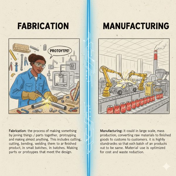
This was the result and i cropped them
Fabrication: the process of making something by joining things / parts together,
prototyping and making almost anything. This includes cutting , bending , welding them to create a finished product,
in small batches. Making parts or prototypes that meets the design.
Manufacturing: it could be in large scale, mass production, converting raw materials to finished goods for customers.
it is highly standardised so that each batch of the products turns out to be same.
Material use is optimised for cost and waste reduction.
Digital fabrication- is the process of desiging things using digital softwares then producing them using computer- controlled machine.
Machines like 3d printers, lasercutter, cnc machines, vinyl cutter.
The basic workflow- designing on computer >> send the file to a machine >> machine makes the tangible object out of it automatically.
CAM - Computer Aided Manufacturing - it is a software process of converting cad designs into machine instructions(toolpath / g-code).
Basically it is like translator who translate the design language into machine language, so that machine can understand:
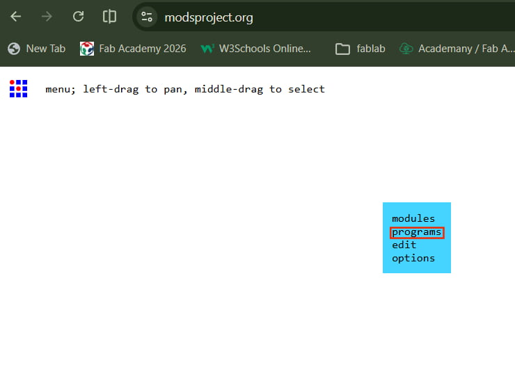
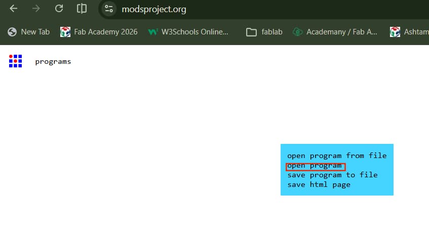
Here in fablab, we basically use ModsProject to send files to machine, which is browser based CAM
open-source platform where you can connect fabrication machines and send file to machine.
As its name mods, it is modular tool space where small functional blocks / modules connects together to create
manufacturing workflow, like an ecosystem for digital fabrication machine.
It is developed at MIT's center for bits and atoms by Prof. Neil Gershenfeld.
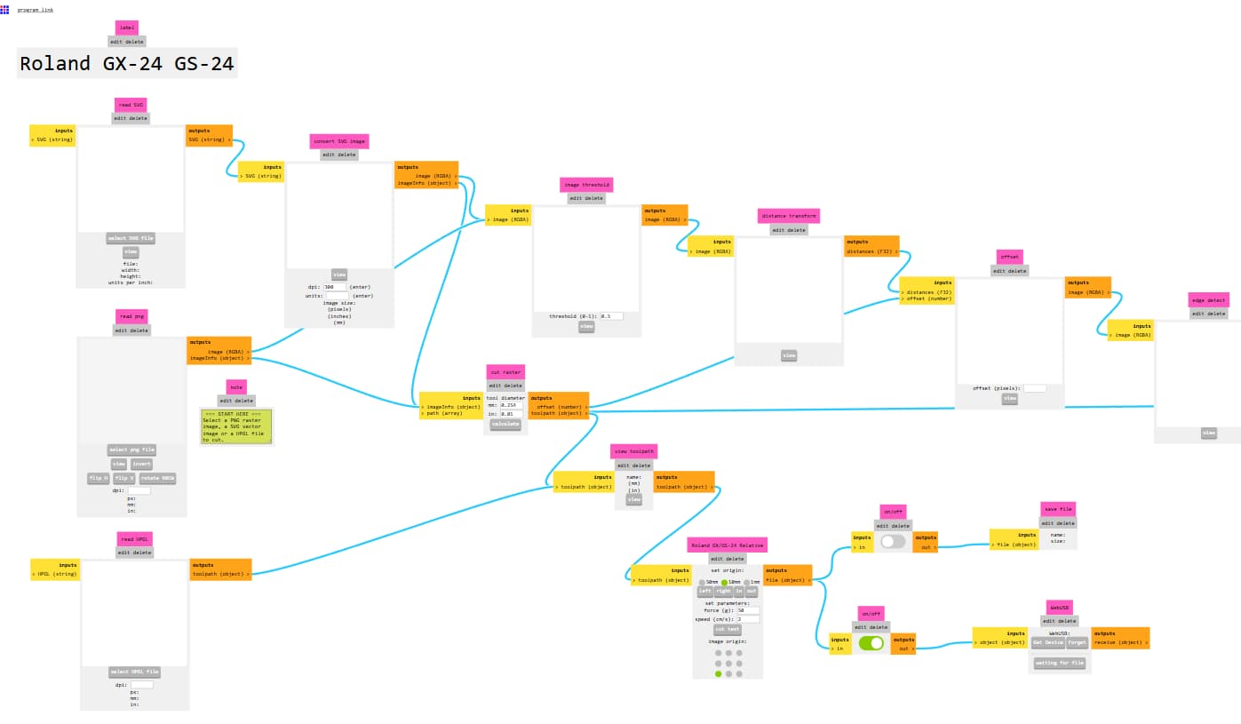
Workflow: import design files in svg then convert them into paths, sends machine instructions directly to machines (like vinyl cutter) using “send file to device.”.
This week we have computer controlled cutting for that we are learning how to use vinyl cutter, laser cutter.
Cut something on Vinyl Cutter.
What is vinyl cutter?
A computer-controlled cutting machine that uses a small blade to cut designs into a sheet of vinyl. The cutter is guided by a design that is created on a computer and sent to the machine.
The excess vinyl is then removed by tweezers, blades, leaving behind the desired design. For applying the design to a surface can be done using heat press or adhesive.
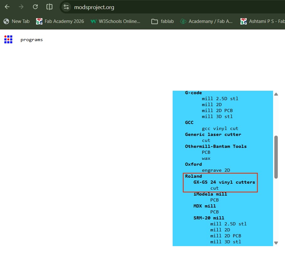
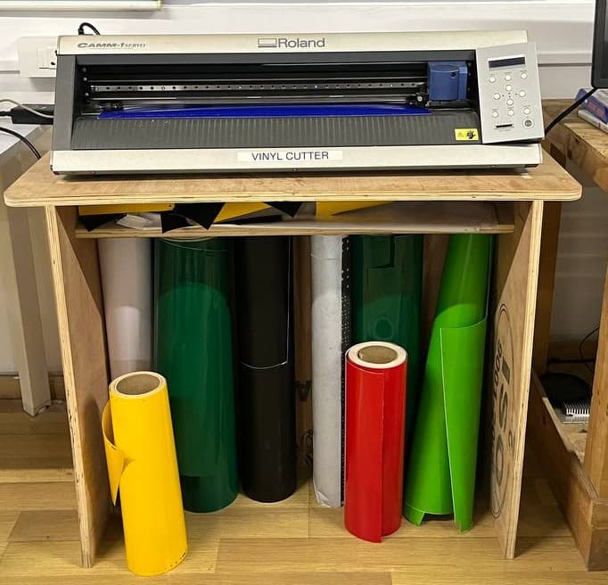
In our fablab, we have roland gs-24; as it is pretty old the control button needs extra force while pressing,
sometimes for enter button - either long press it or press short, depends on its mood.
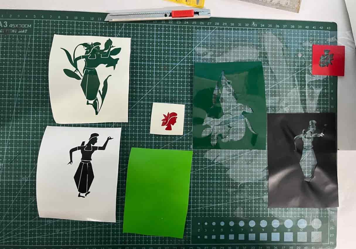
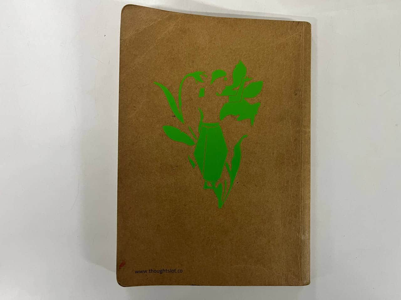
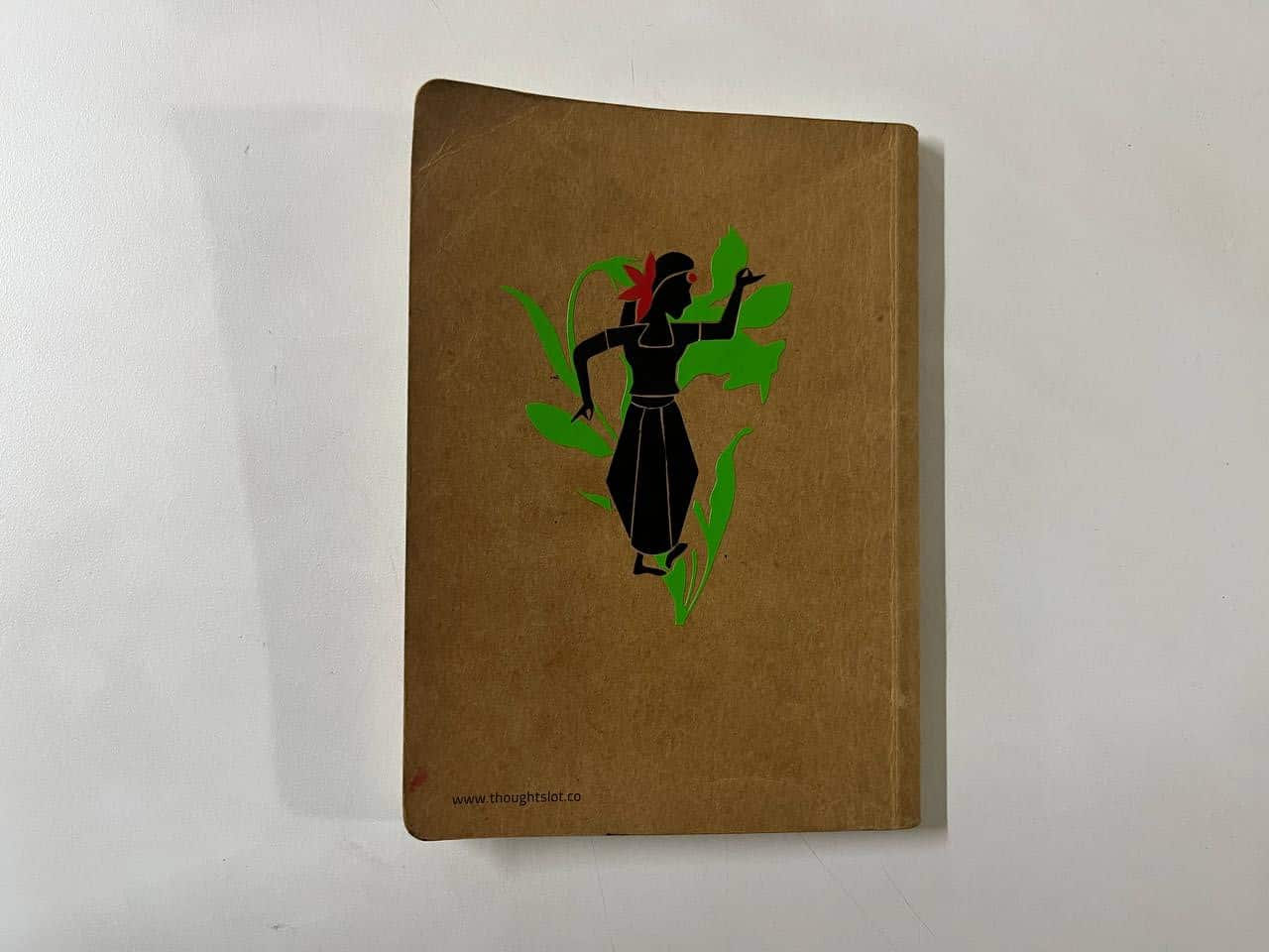
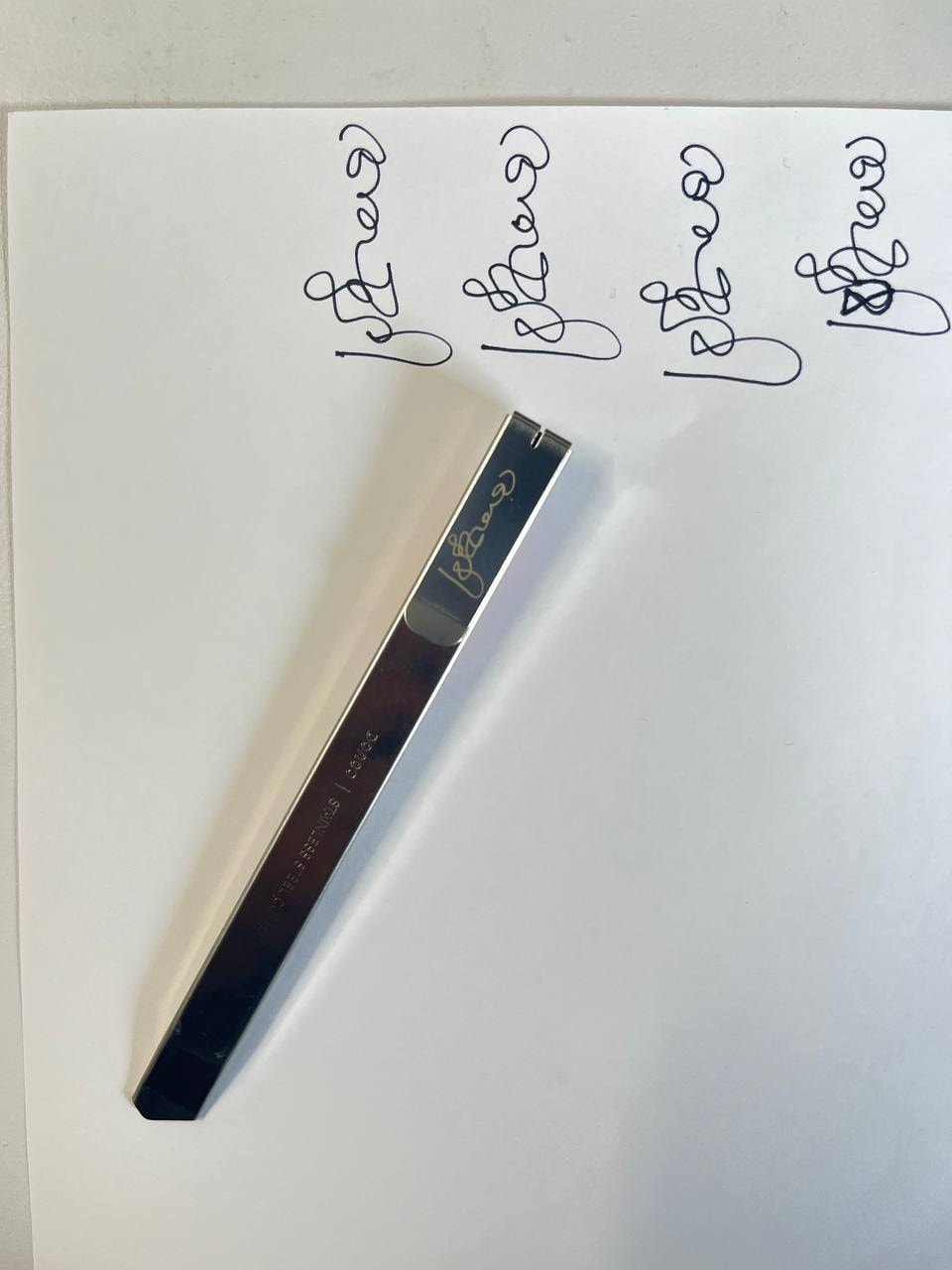
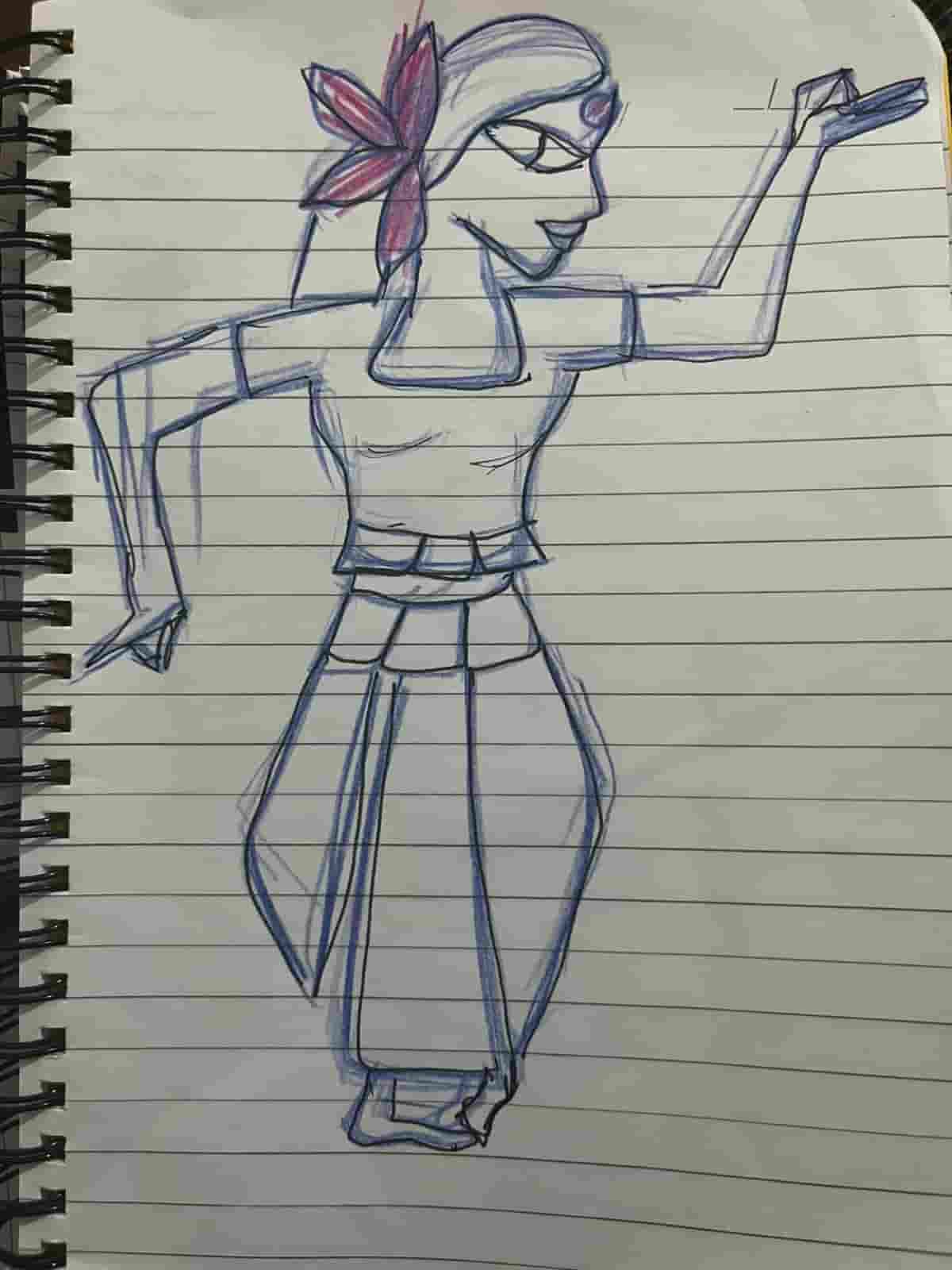
I started by designing the sticker in Inkscape. First, I sketched an Indian classical
dancer on my notebook and then imported that sketch into Inkscape.
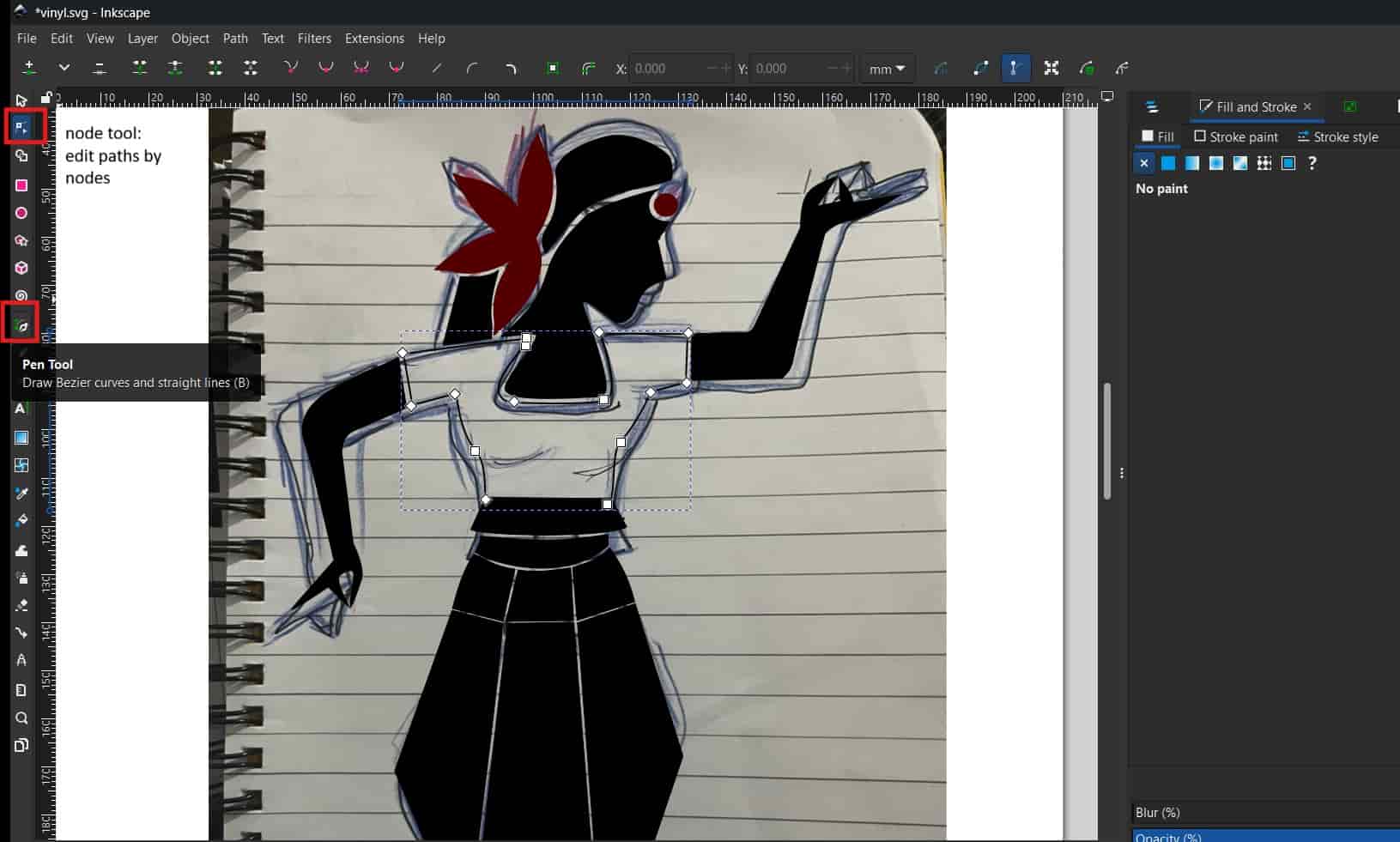
Pen Tool
Using the Pen tool, traced the sketch on the digital canvas
Node Tool
Using the Node tool, adjusted the paths to refine the shapes.
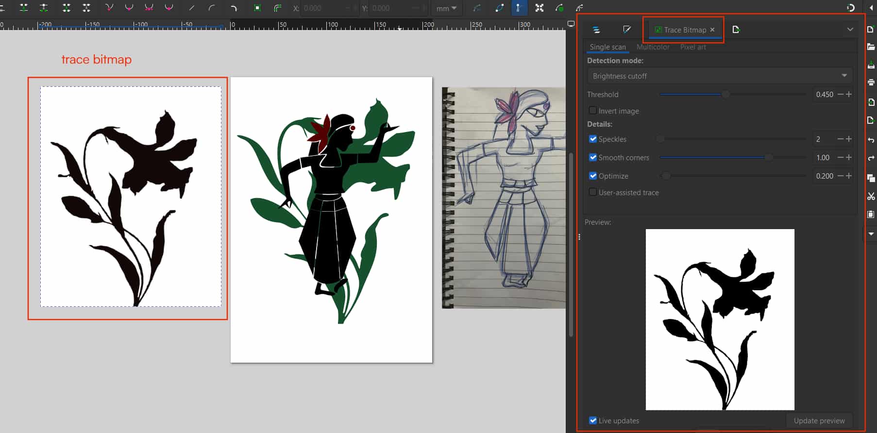
I wanted to add a flower behind the dancer, so I downloaded a flower image from
Pinterest and imported it into Inkscape
Trace Bitmap
Using the Trace Bitmap feature, converted the image into a vector graphic.
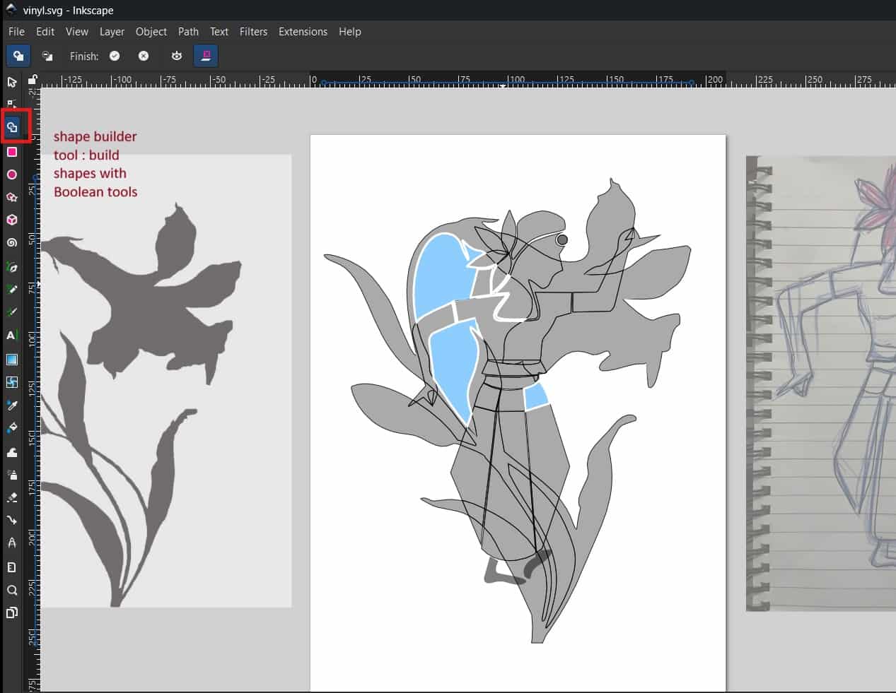
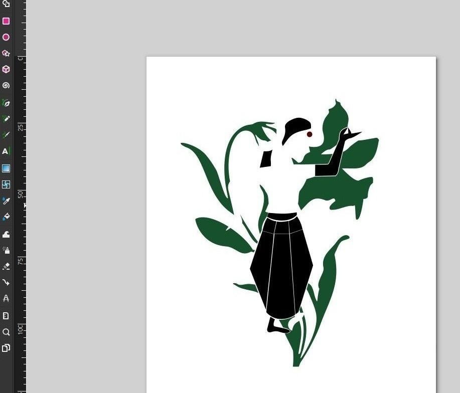
One limitation of vinyl cutters is that they can cut only solid-colored vinyl, so multi-color designs must be cut separately for each
color and layered during application. Since my design had two main elements and three colors,
I used shape builder operations.
Shape Builder Tool
Build shapes with Boolean tool, i used it (subtract and join/union) to separate the parts for each color.
Each color layer was saved as a separate file and resized to the required dimensions.
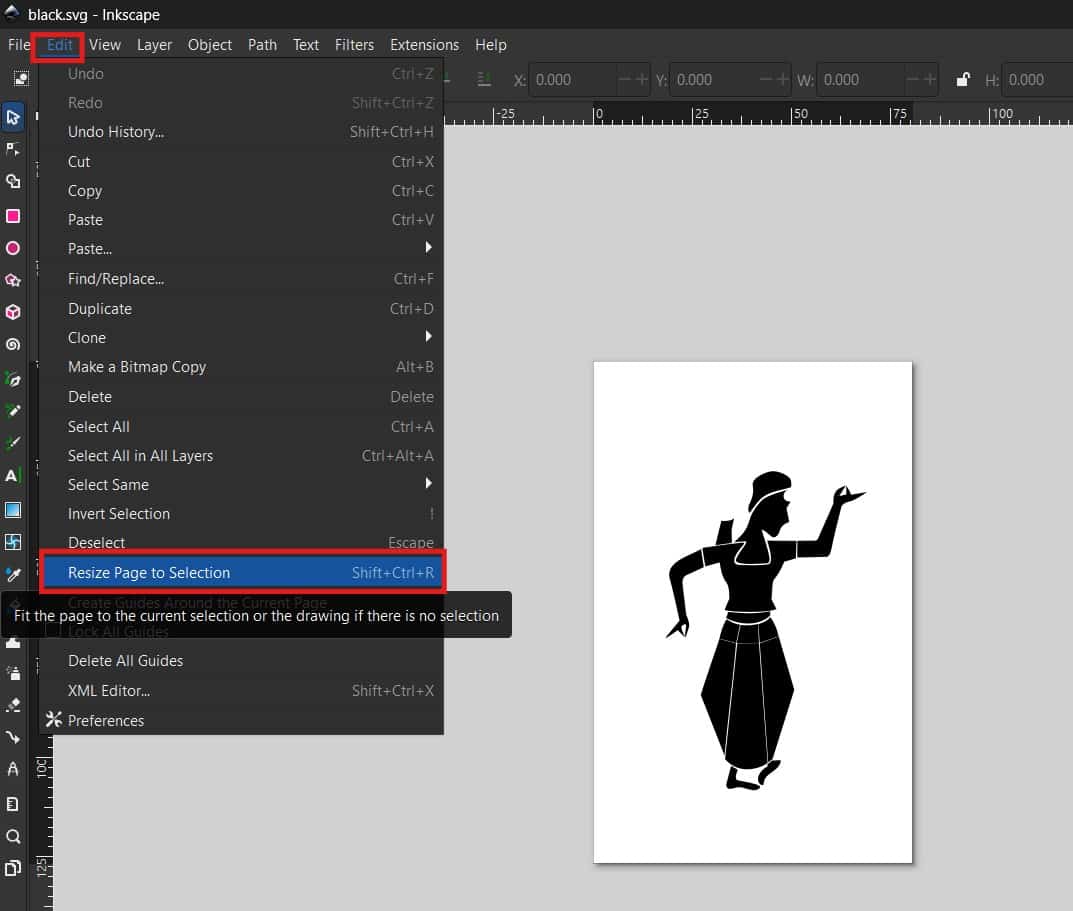
Resize Page to Selection
I resized the canvas using Ctrl + Shift + R to fit the page to the design, ensuring proper cutting without misalignment.
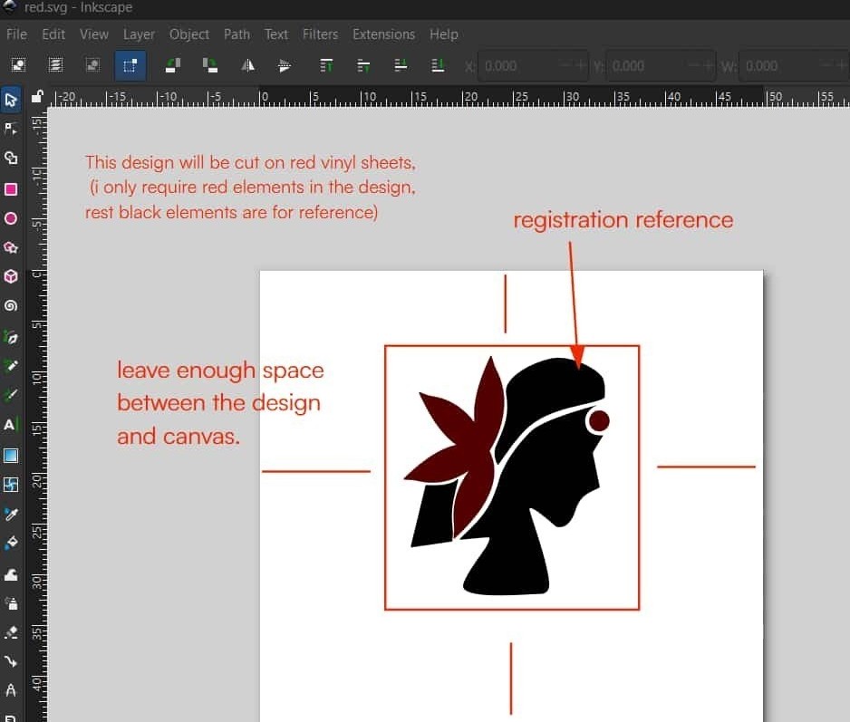
I also left some margin around the design, because if the design is too close to the edge,
unwanted gaps may appear while generating the cutting paths.
Registration reference were left in each file for accurate alignment while layering the colors.
Finally, I saved the files in SVG format for cutting.
2
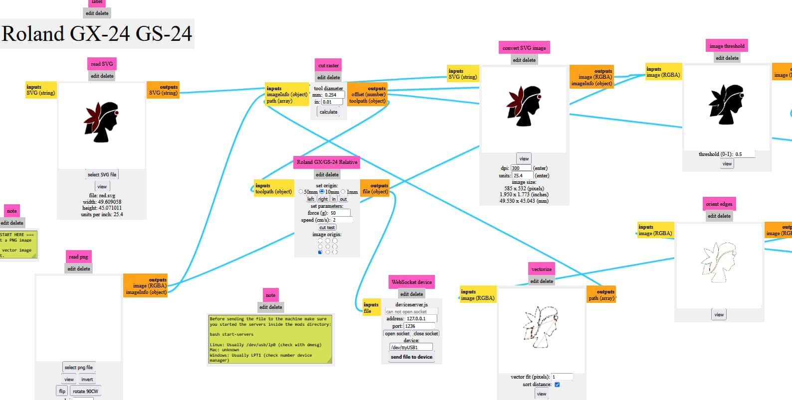
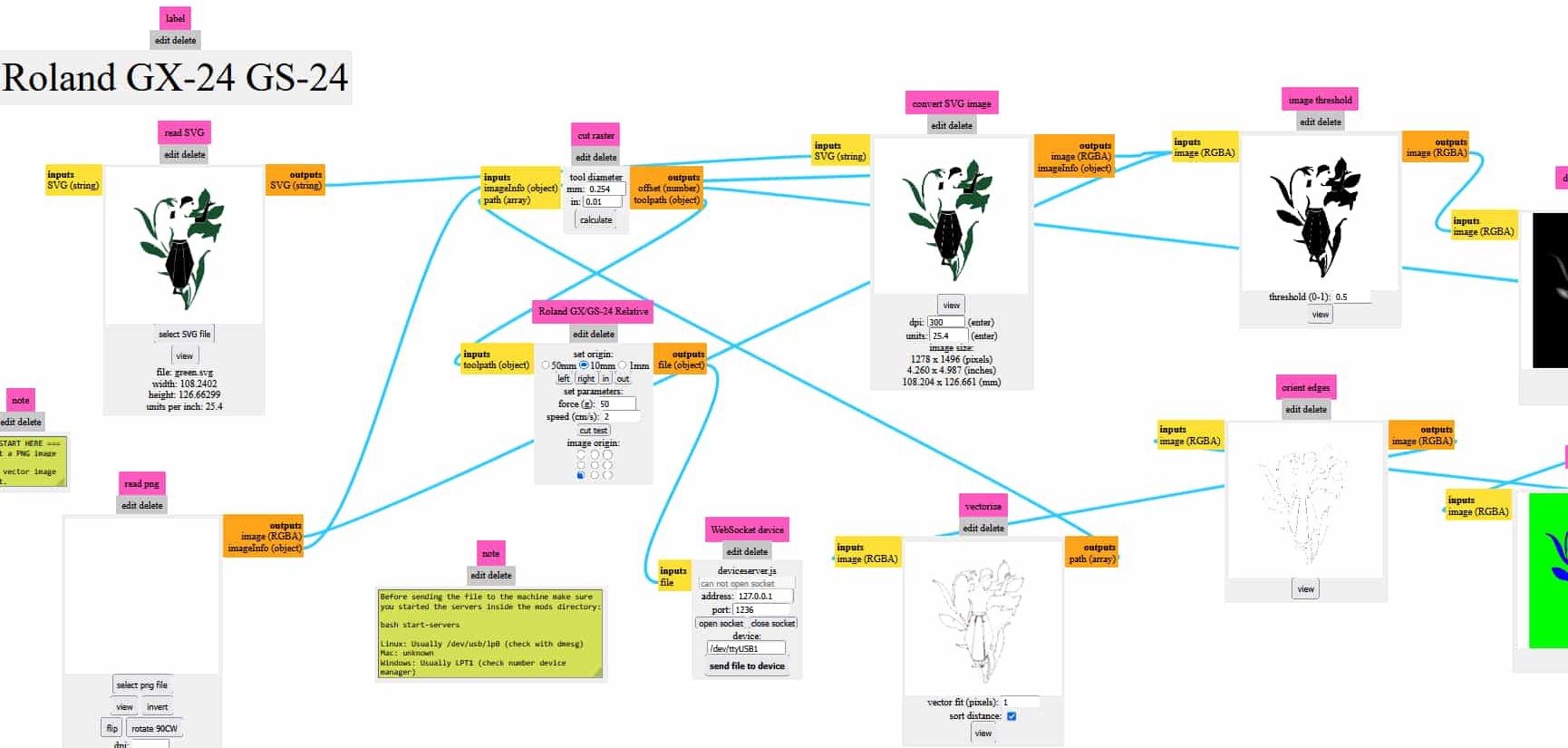
Mods Project: Toolpath Calculation
Open modsproject and upload the svg file in it; for that use option
“select svg file”>> then press calculate which calculates toolpath>> can check the path using “view”>>”send file to device”
3
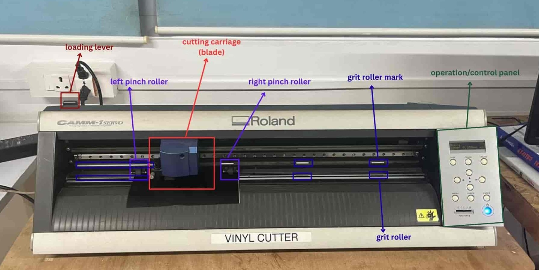
Vinyl Cutter Workflow
I'll start with the mistakes I made, so you can be careful and avoid them.
I did not pull the loading lever down while inserting the vinyl, and I tried adjusting the left and right pinch rollers from the front.
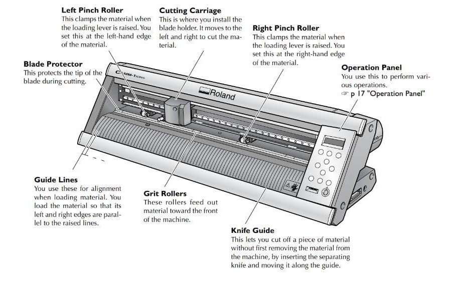
How to use Roland gx-24
Loading Vinyl
Pull the lever down while loading the vinyl rolls.
Move the blade holder to the right end using cursor key for avoiding interference.
Adjust the pinch rollers from the back side and place them on the grit roller markings
and pull the lever up to lock.
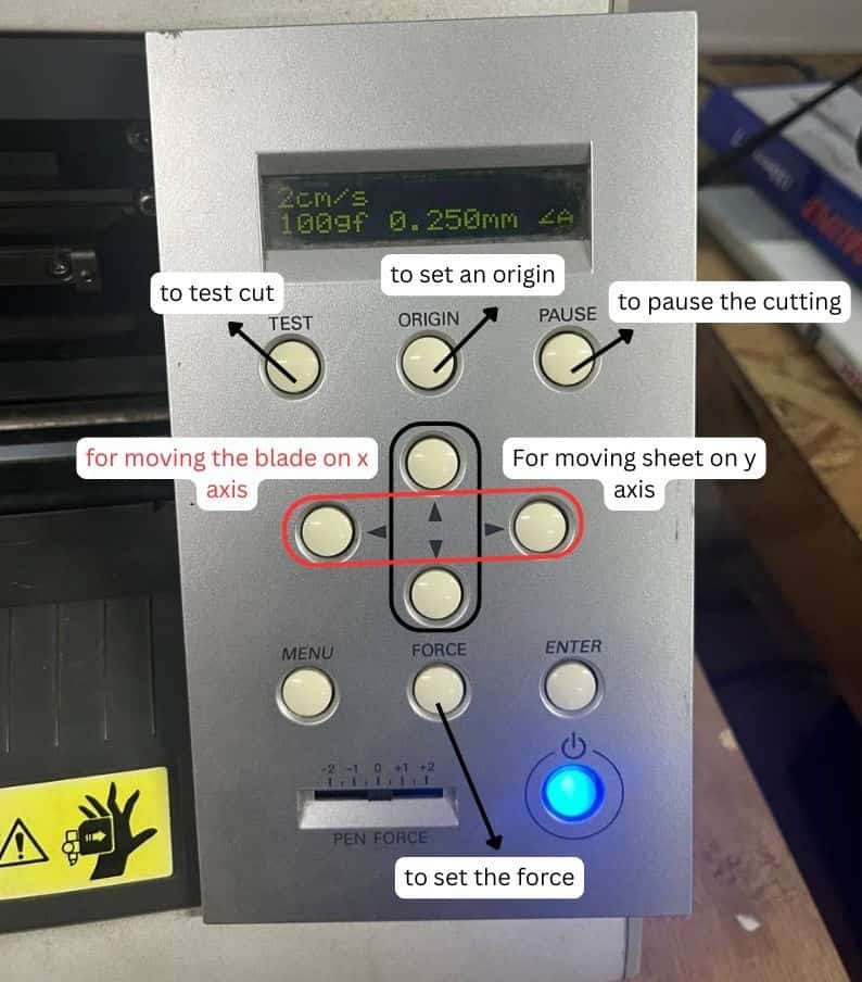
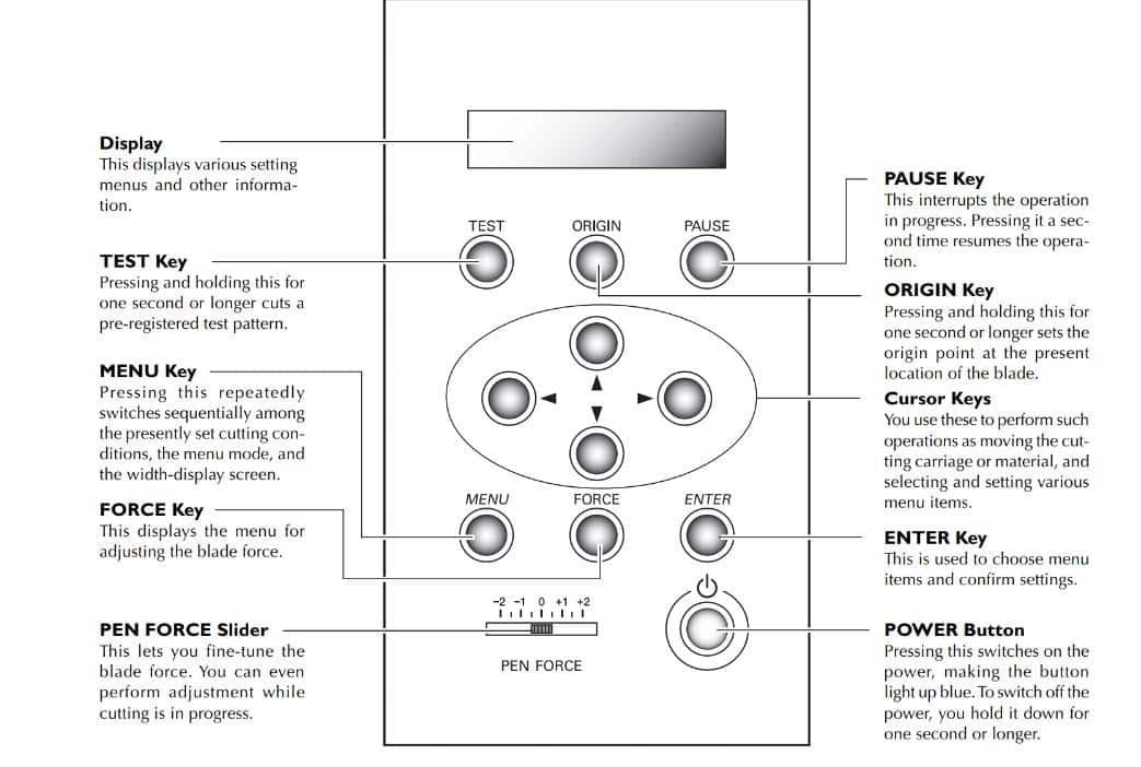
Setting Position
Use the cursor keys (Up & Down- y coordinate) to adjust the vinyl position and press Enter.
Use the cursor keys (Left & Right - side keys - x coordinate) to position the blade and press Set Origin.
Now machine is ready to cut.
After Cutting
Move the sheet forward using cursor keys, cut the vinyl with a blade or scissors,
and pull the lever down before unloading.
4
Final Sticker Assembly
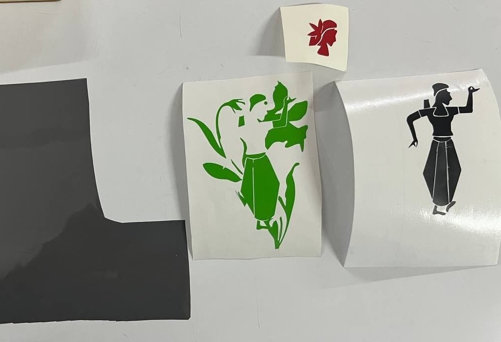
For my sticker, I used three vinyl colors: red, green, and black.
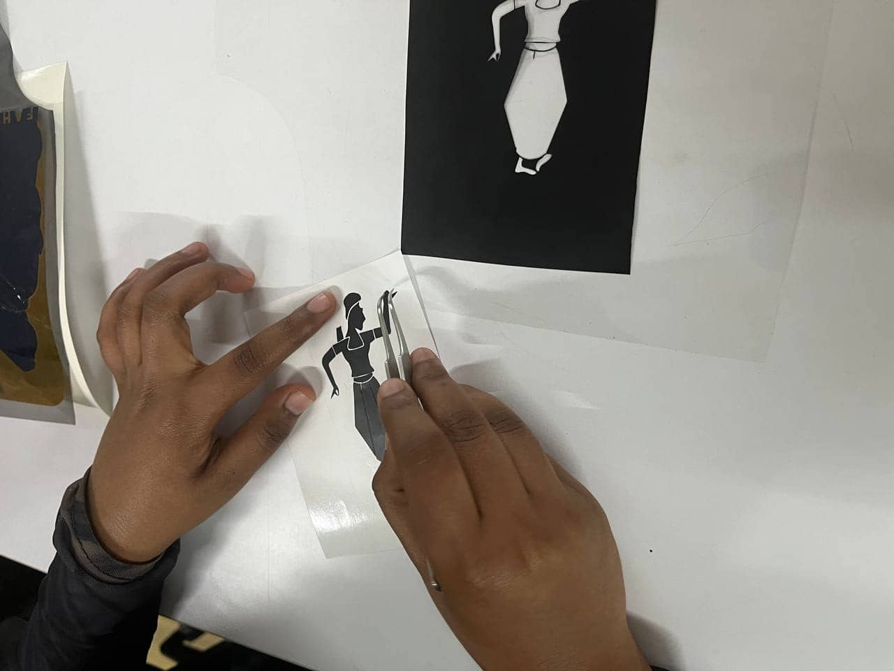
After cutting, I removed the unwanted vinyl using tweezers and a blade.
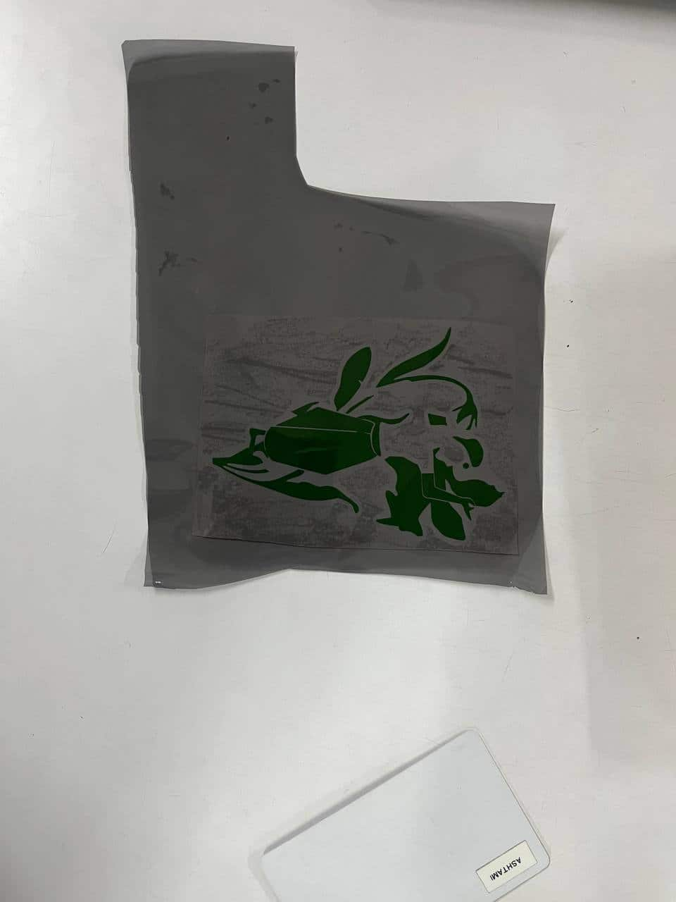
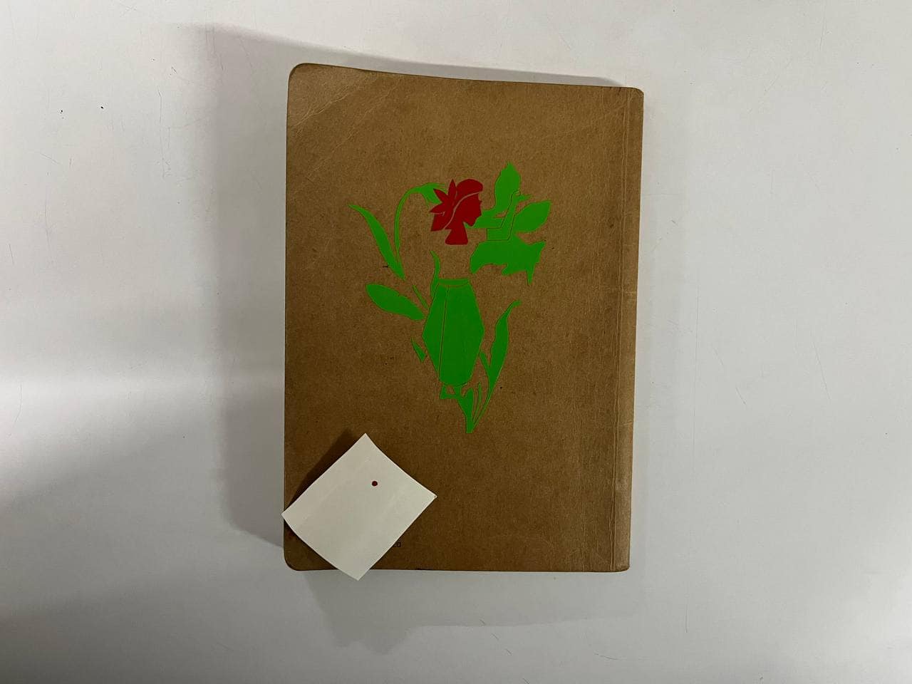
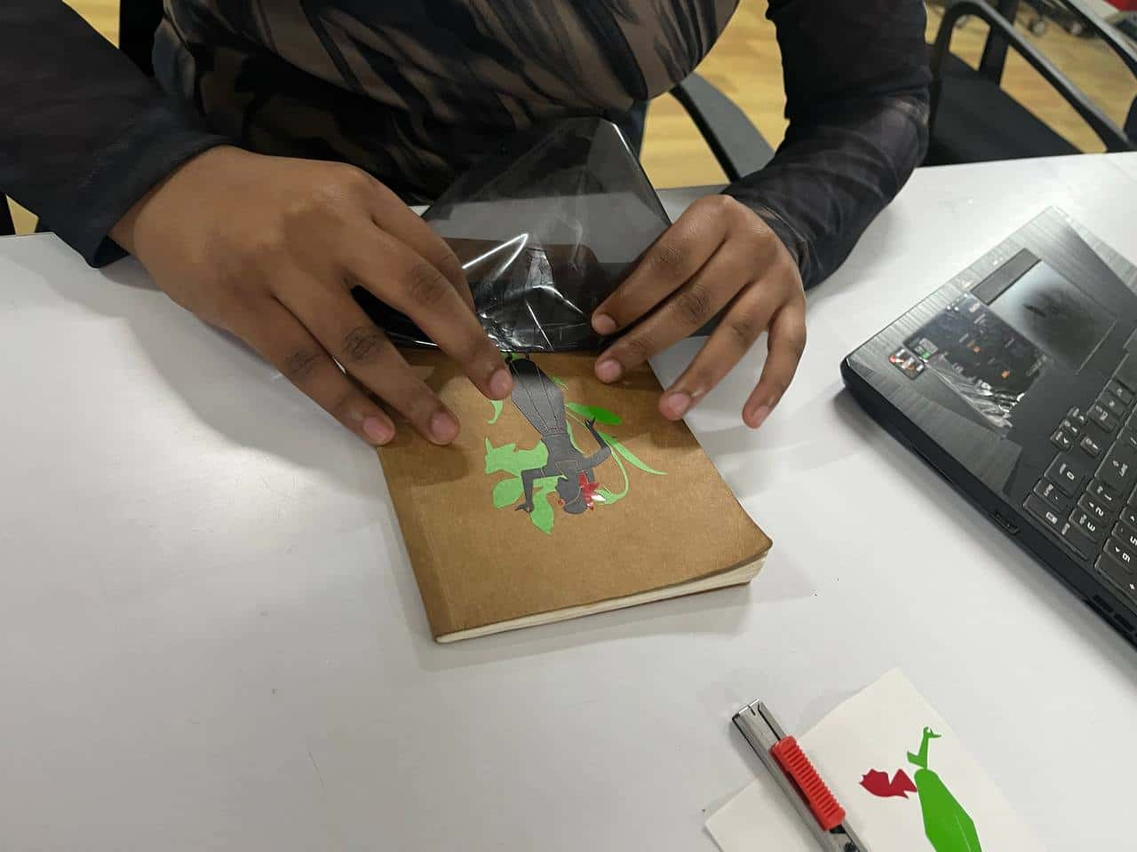
Then I used a transfer (adhesive) sheet to lift and apply the design layer by layer—first green, then red, and finally black.
I reused the transfer sheet for each layer and pasted the final sticker on the backside of my sketchbook.
Reflection
I'm pretty happy with the final result.
The most challenging part was aligning the different colored vinyl stickers accurately while pasting them.
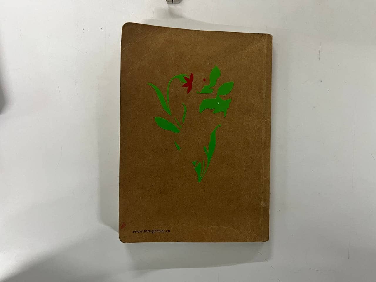
The green vinyl was not very sticky, so some of the smaller pieces did not adhere properly
and became slightly misaligned. Using tweezers helped me realign and place the details correctly, especially the bindi.
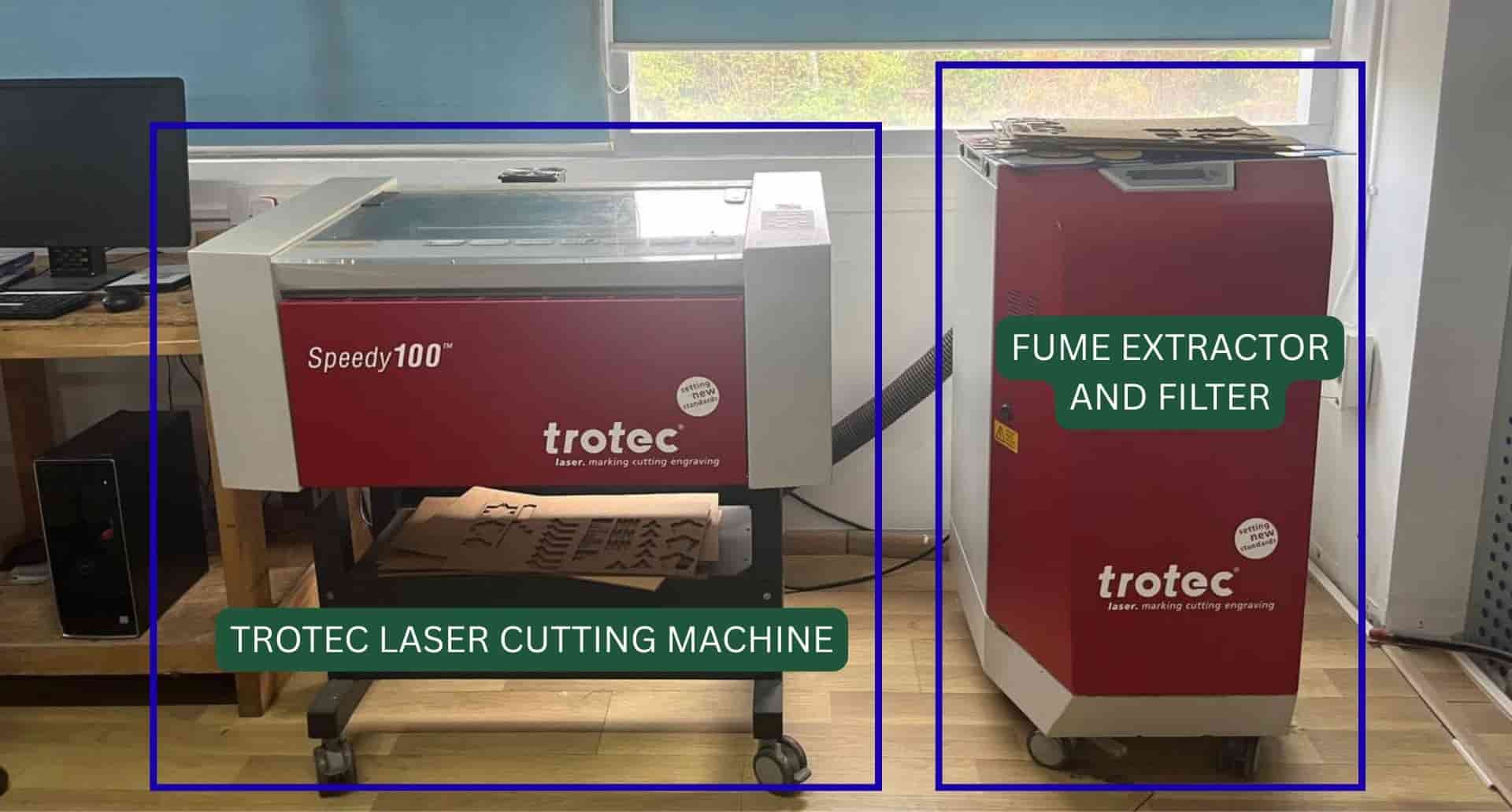
Laser Cutting - Trotrec Speedy 100
What is laser cutting?
Laser cutting is a process where a machine uses this focused beam of light to cut shapes from
materials like cardboard, wood, acrylic, or paper. The laser generates heat, which burns, melts,
or vaporizes the material along a path to create the desired shape.
As a small amount of material is
removed during cutting, we need to consider the kerf when designing parts for accurate fitting.
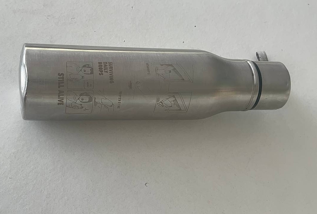
For engraving, it lightly burn the surface to create designs or text.
Trotec Speedy 100 is a laser cutting and engraving machine that uses a focused CO₂ laser beam to cut and engrave materials such as wood, acrylic, cardboard, paper, and leather with high precision.
It has a working area of 610 x 305 mm.
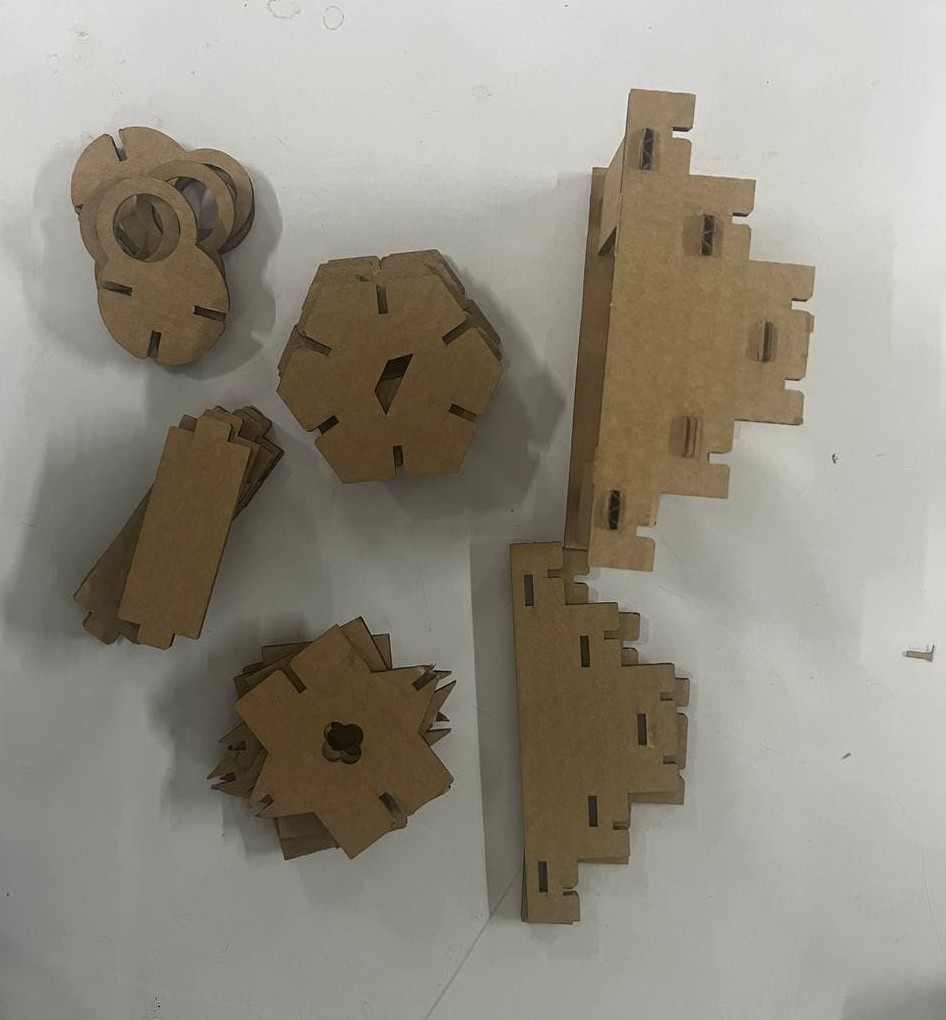
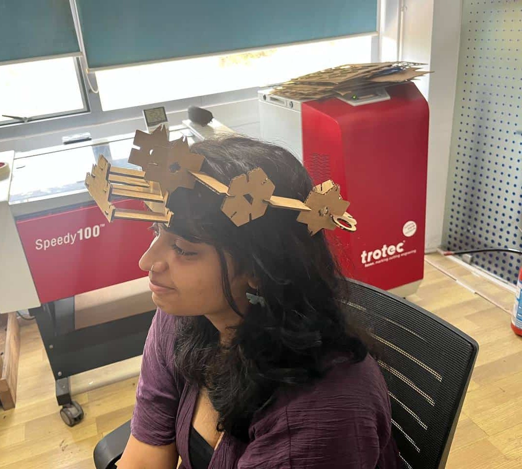
we had to design a parametric construction kit using cardboard as the cutting material.
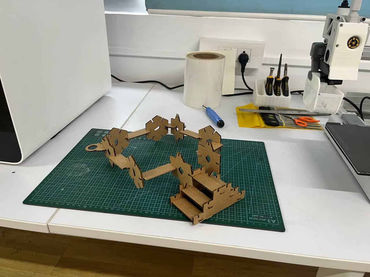
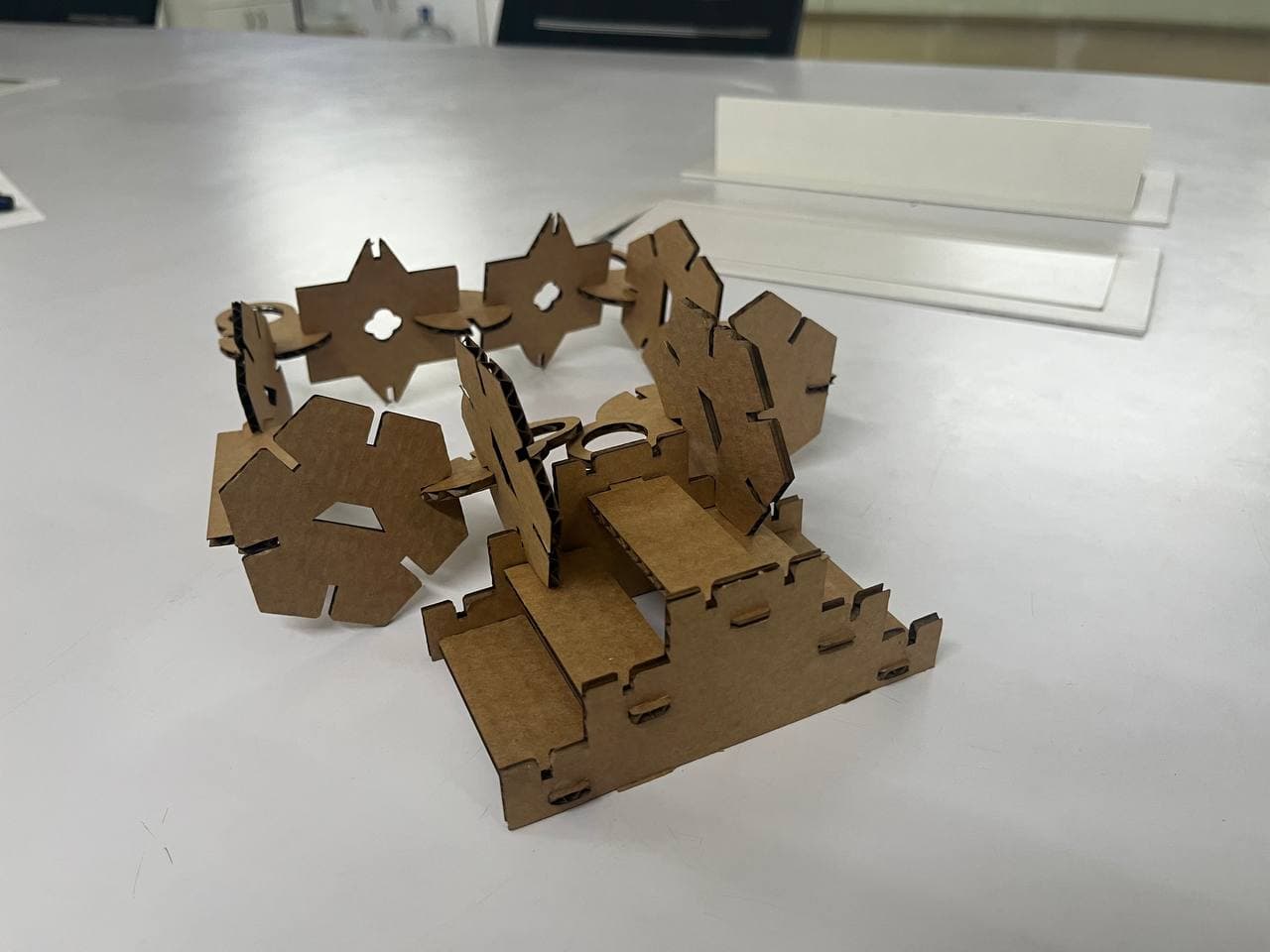
The kit was created with different joints so that the parts can be assembled without glue and can be rearranged to build different structures.
Why parameters?
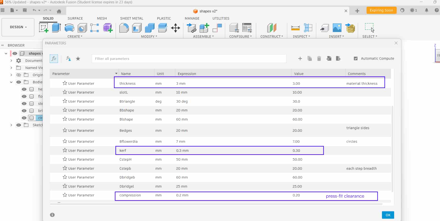
The design was made parametric so dimensions like material thickness, kerf, and press-fit clearance can be changed easily by updating parameter
values instead of editing each sketch individually or redrawing them.
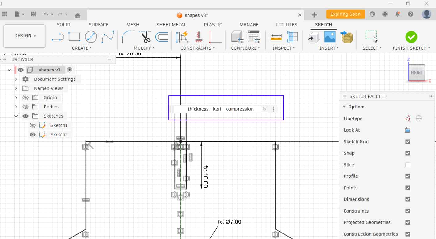
In Fusion 360, I used Create Sketch to construct the shapes and defined the sketch using parametric dimensions.
Tools such as polygon, line, rectangle, circle, offset, and mirror were used, along with constraints, to fully define the sketch.
Kerf
0.3mm
Compression
0.2mm - Press fit clearance
Thickness
3mm - Material thickness
I sketched each component one by one and extruded them.
A chamfer was applied to the edges of the slots to make insertion easier.
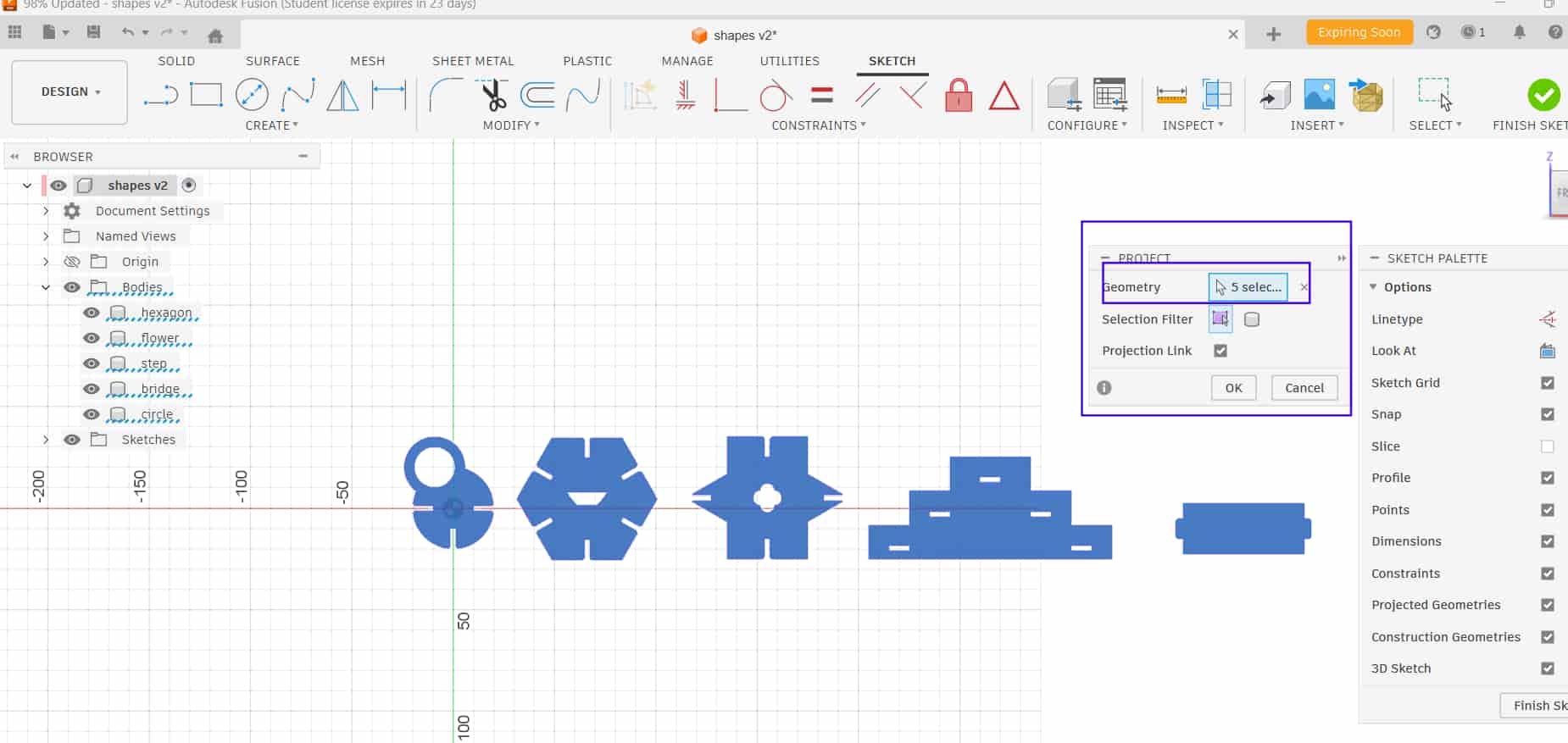
In a new sketch, I used:
Project tool
Press "P"/ you find it in "create"to project the sketch onto the plane.
Afterward, save it as DXF.
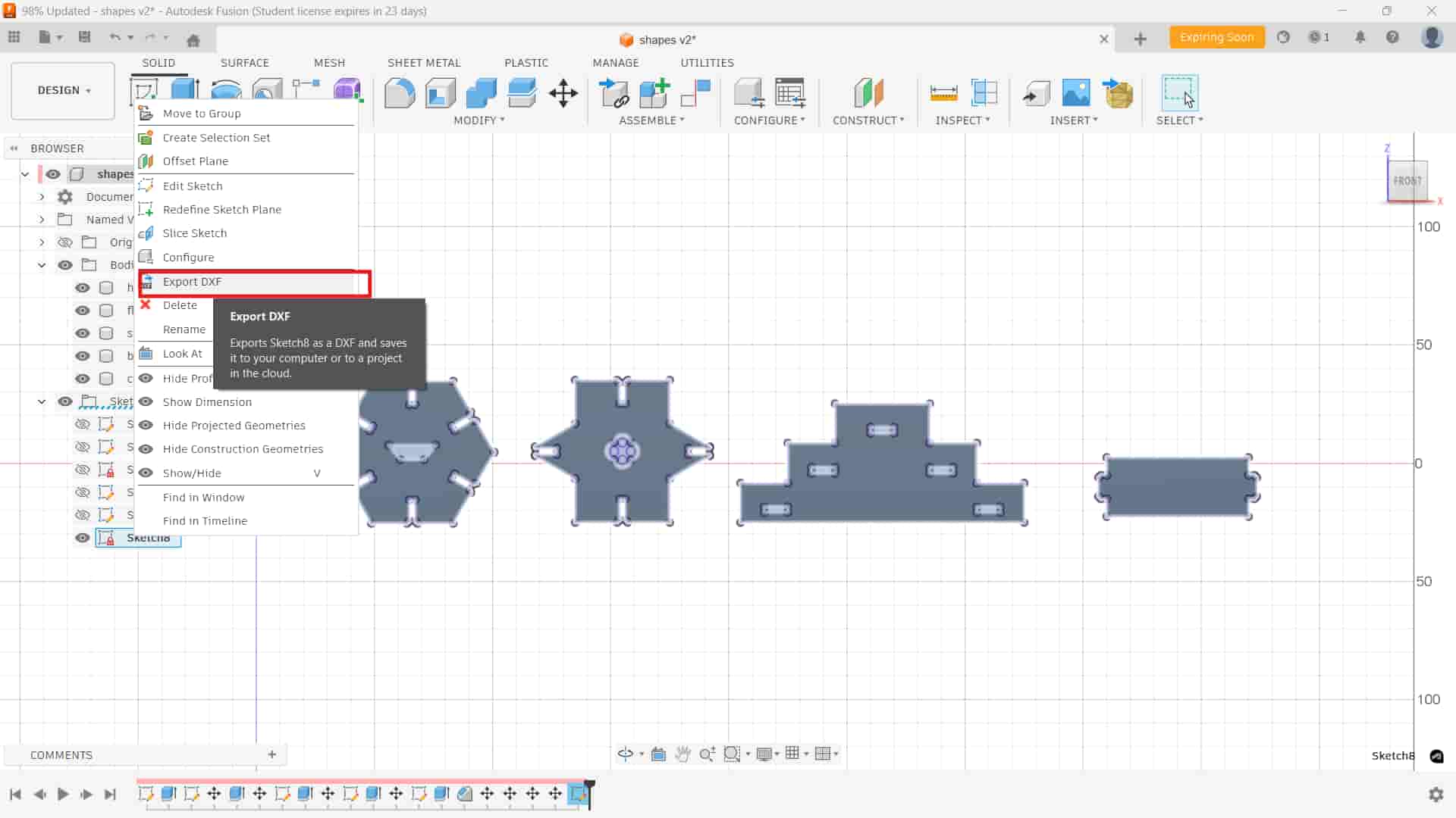
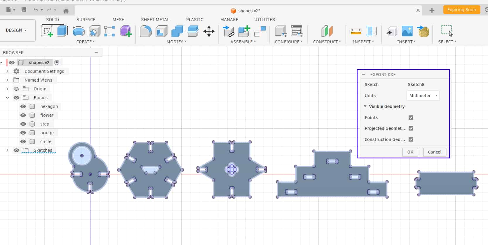
Export DXF
Right-clicked on the projected sketch and exported it as a DXF file, which exports the 2D sketch for cutting.
2
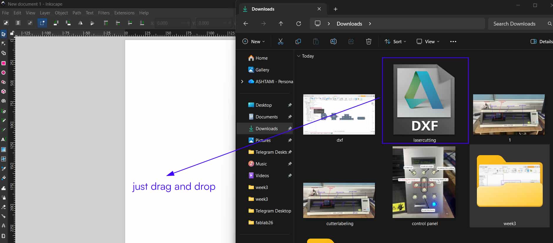
Importing to Inkscape and Editing
Open the DXF file in Inkscape by dragging and dropping it into the workspace.
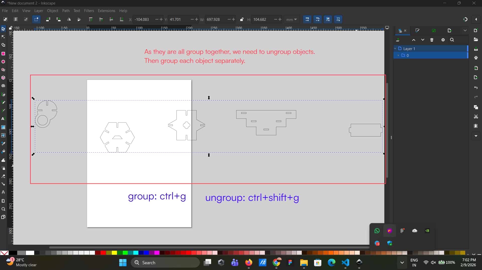
Then ungroup the elements and group each object individually as needed.
Ungroup
As they are all grouped together, need to ungroup the elements. To ungroup: ctrl+shift+g
Group
For grouping elements, select the specific elements, then ctrl+g
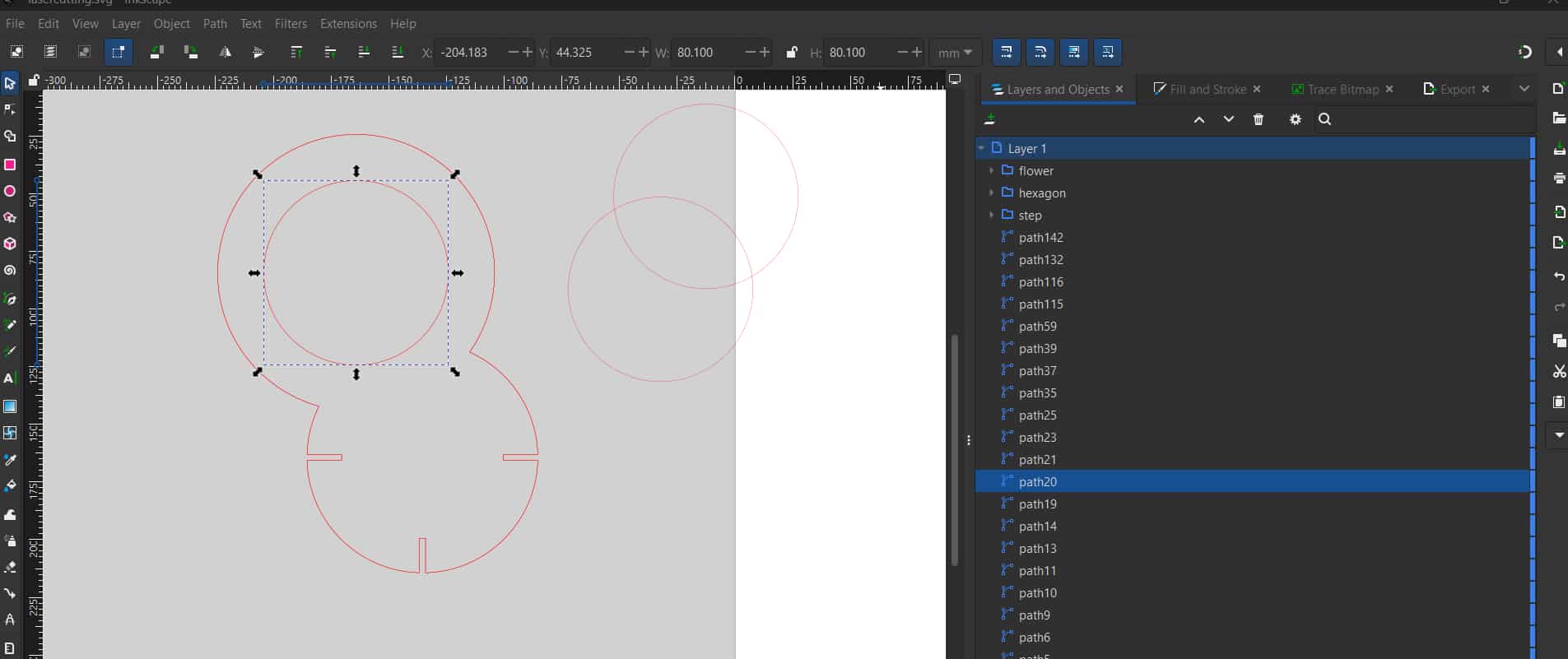
The mistakes (try not to do these, be carefully)I made was:
That some sketch paths were duplicated multiple times
(either during DXF export from Fusion 360 or while editing in Inkscape).
Because some paths were duplicated, the machine continued cutting along the same path
multiple times, which caused the laser to pass repeatedly over the same area and resulted in small sparks.
Therefore, it is important to check and remove any duplicate or overlapping paths in Inkscape before sending the file for cutting.
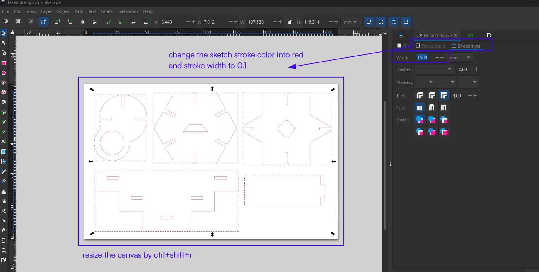
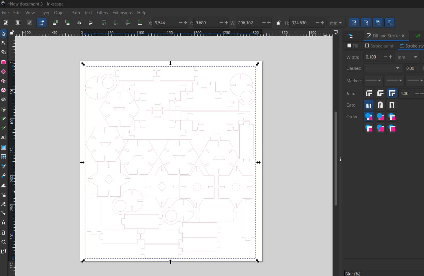
After grouping the objects,
Stroke Paint
change the stroke color to red and set the stroke width to 0.1 mm,
as in the machine's (Trotec laser cutter) material database settings where
red color is set for cutting.
Finally resize the canvas (ctrl+shift+r) and save as SVG file.
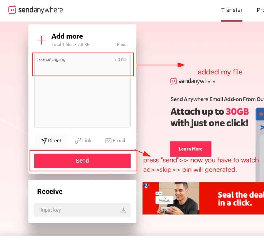
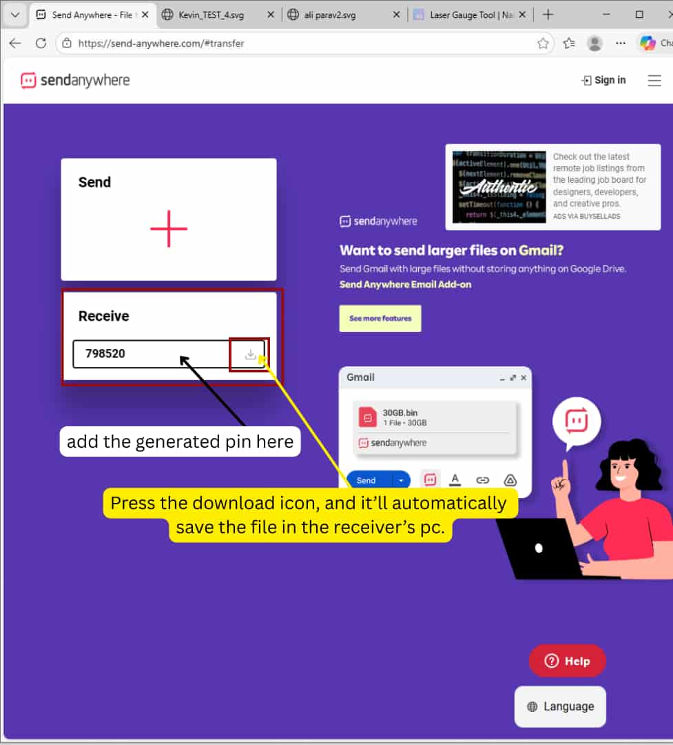
To send the file to the Fab Lab system connected to the Trotec machine, we used Send Anywhere.
First, upload the SVG file >>click Send, which generates a PIN code.
Receiver's system
Then, on the receiving computer, enter the same PIN code to receive and download the file.
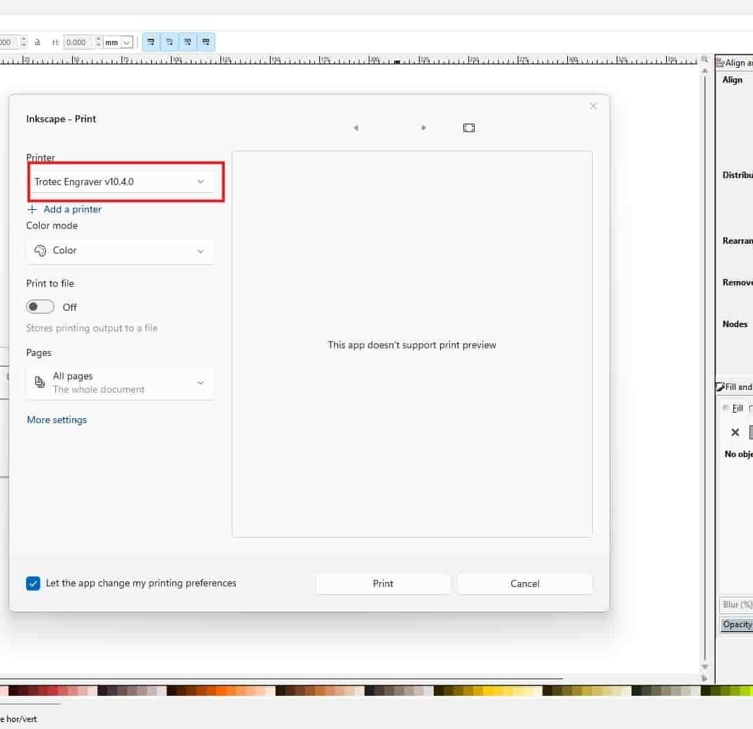
Inkscape >> Send file to printer
Open the file in Inkscape on the Fab Lab PC and press Ctrl + P to print.
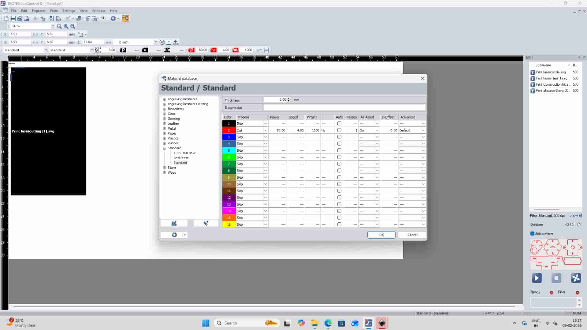
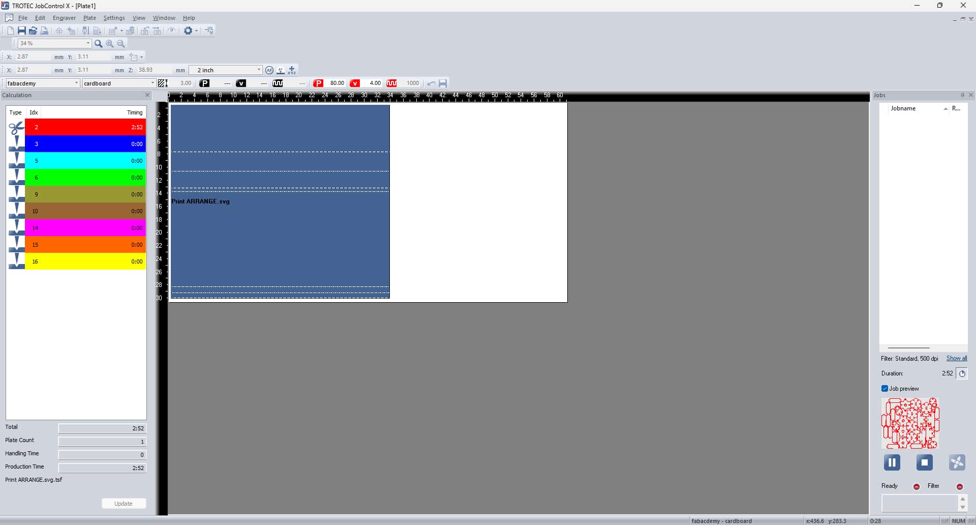
Select the Trotec Engraver, which opens the file in Trotec JobControl software.
4
Setting up machine and Trotec JobControl software
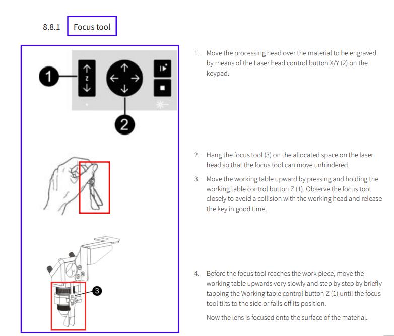
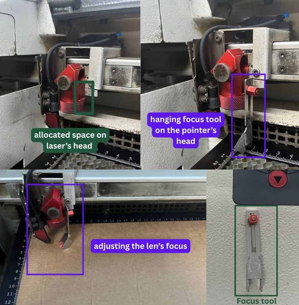
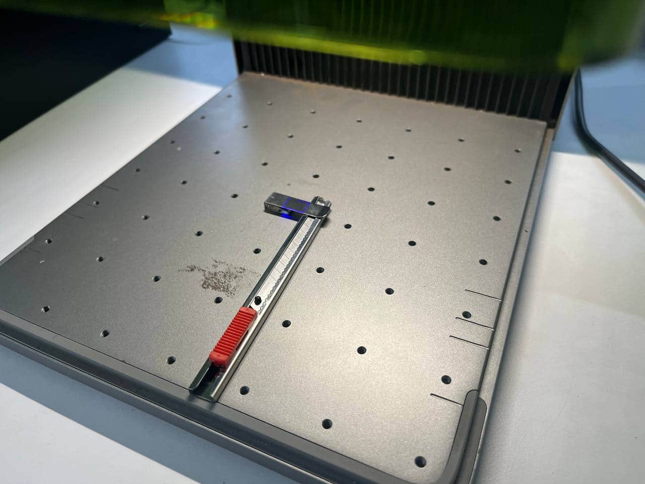
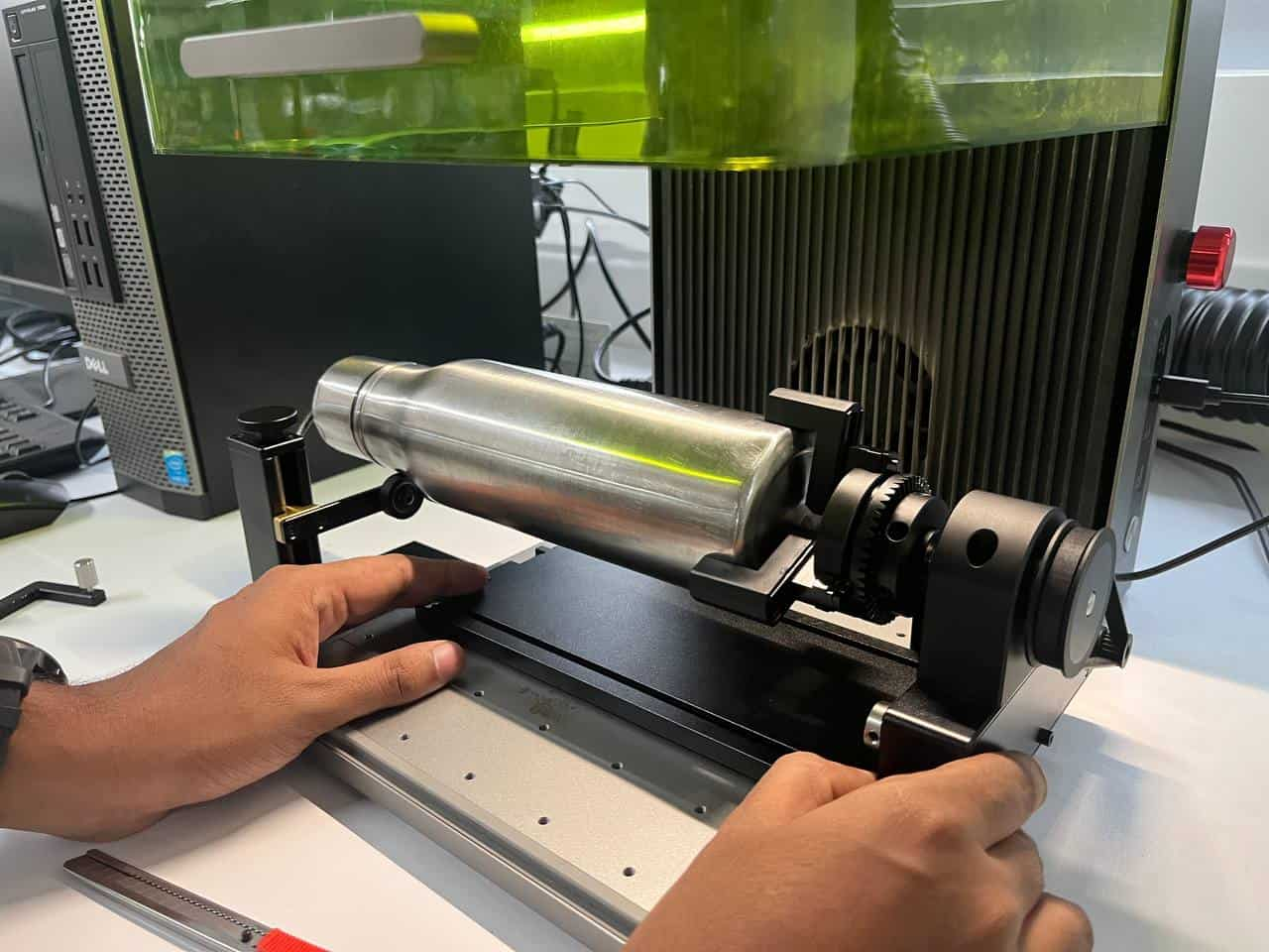
Setting focus
Go to the laser cutter machine. Hang the focus tool in the allocated space on the laser head.
Raise the working table using the Z-axis control until the focus tool just touches the material
surface and tilts or falls, this indicates that the lens is properly focused.
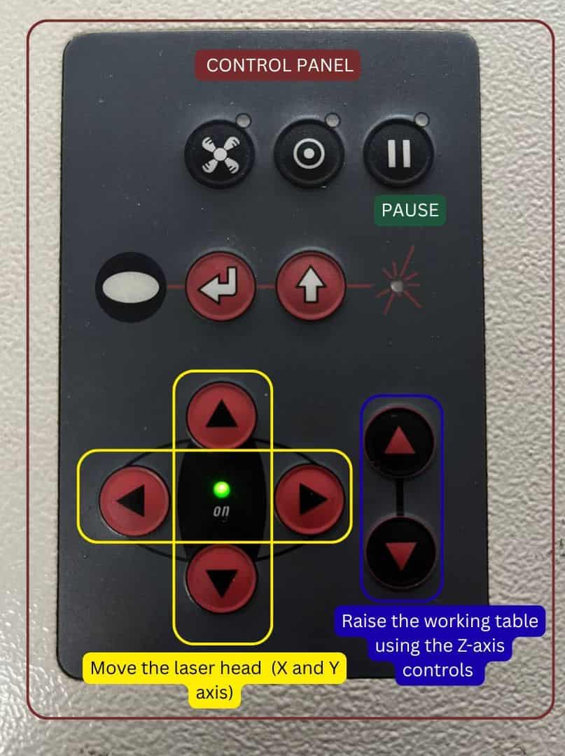
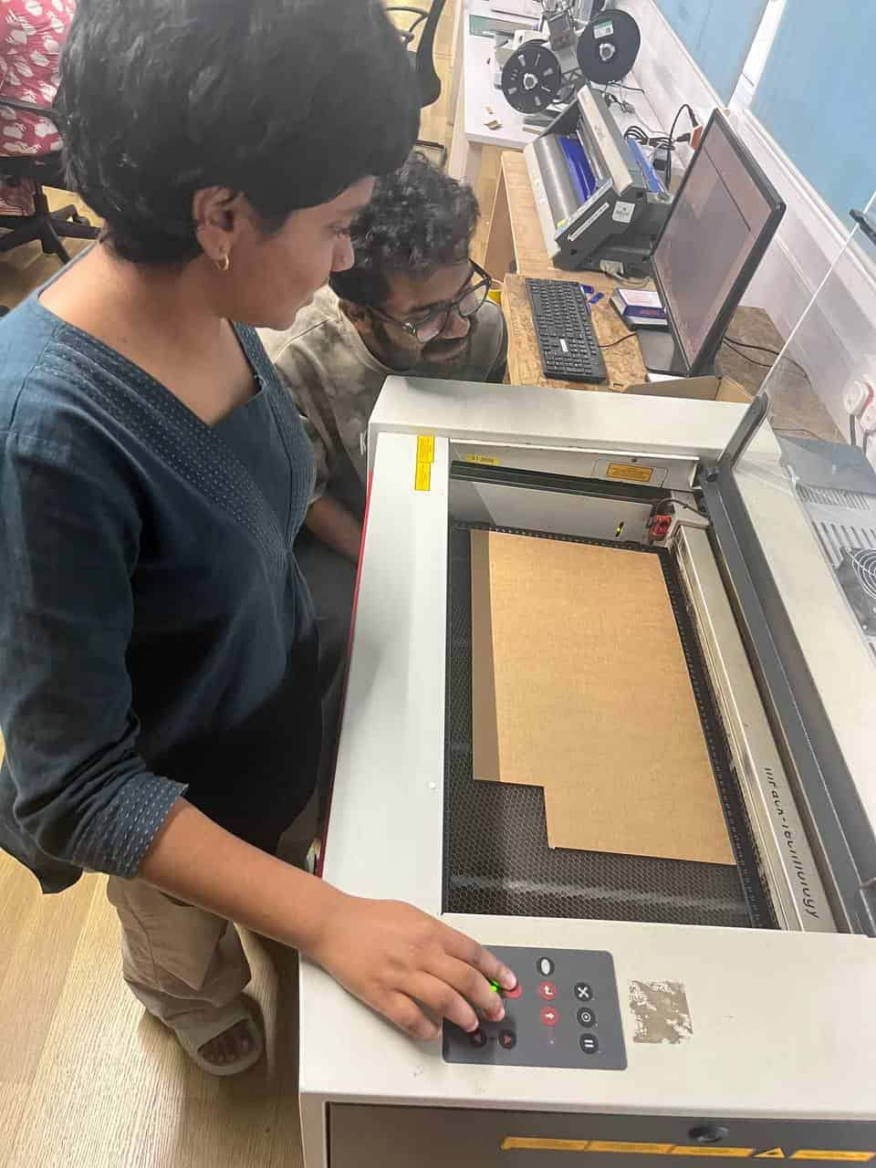
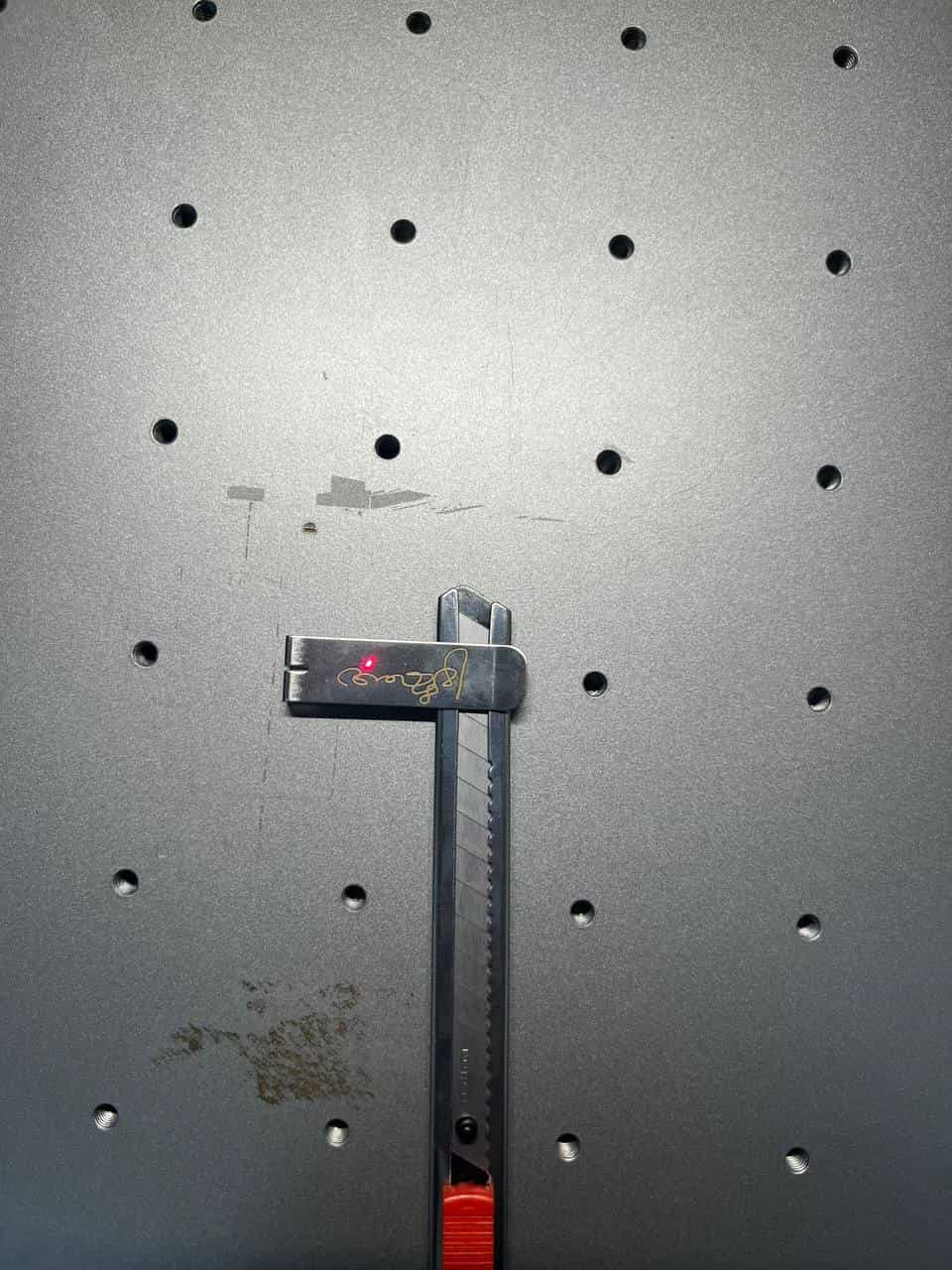
Setting Origin
Move the laser head to the desired starting point on the material using the cursor keys (X and Y coordinates).
The small red laser pointer shows the exact cutting position.
Return to the computer, align the sheet edge with laser pointer in the software.
For aligning the laser point you can either drag the cutting piece selection to the pointer or manually go to the machine control panel and adjust them.
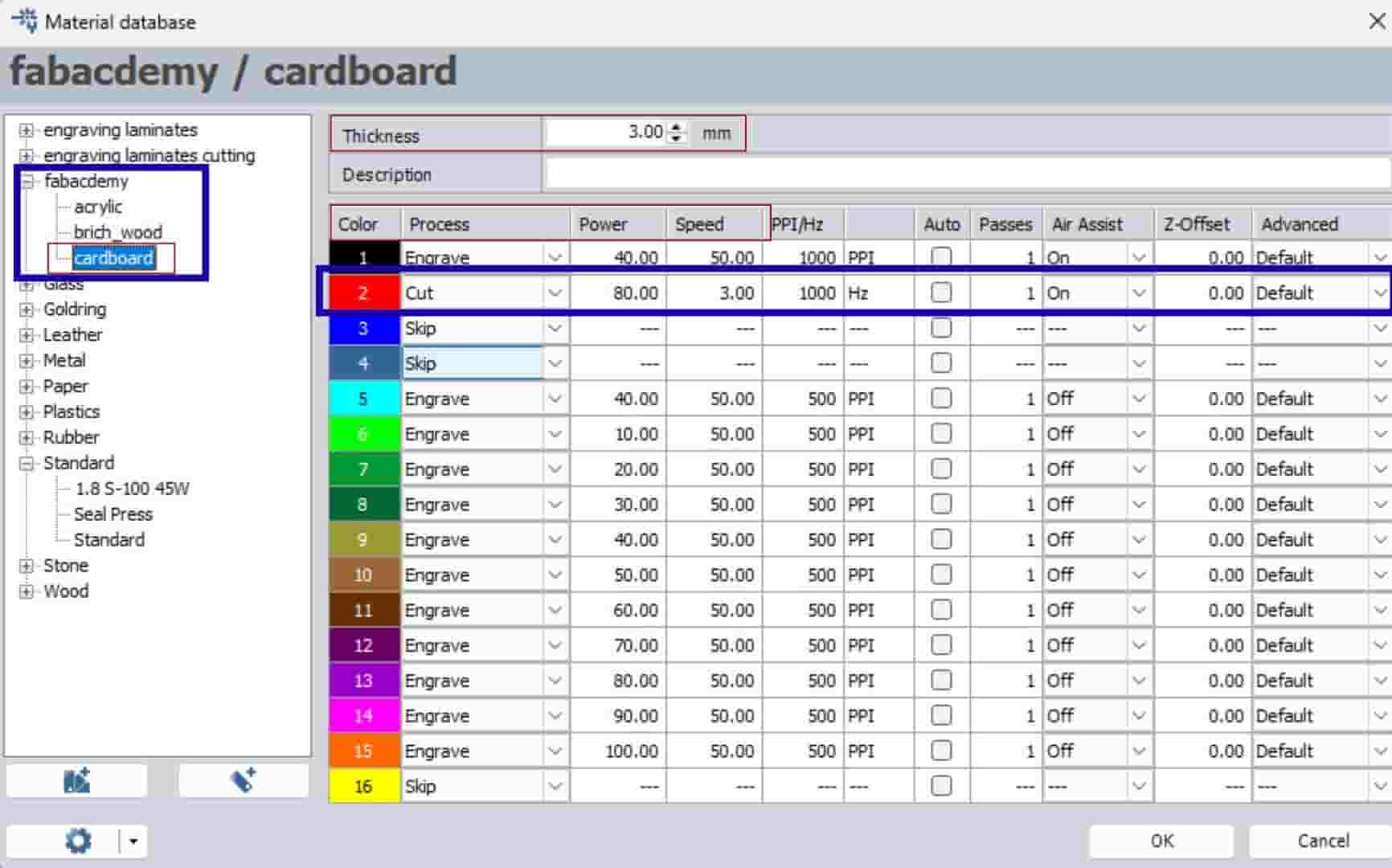
Material Database
choose the correct material settings (power, speed, process) from the material database.
From the group assignment, we performed several test cuts to find suitable laser settings for cardboard.
We found that a power of 300, speed of 3, and 1 pass gave a clean cut without getting burnt and worked well for the material.
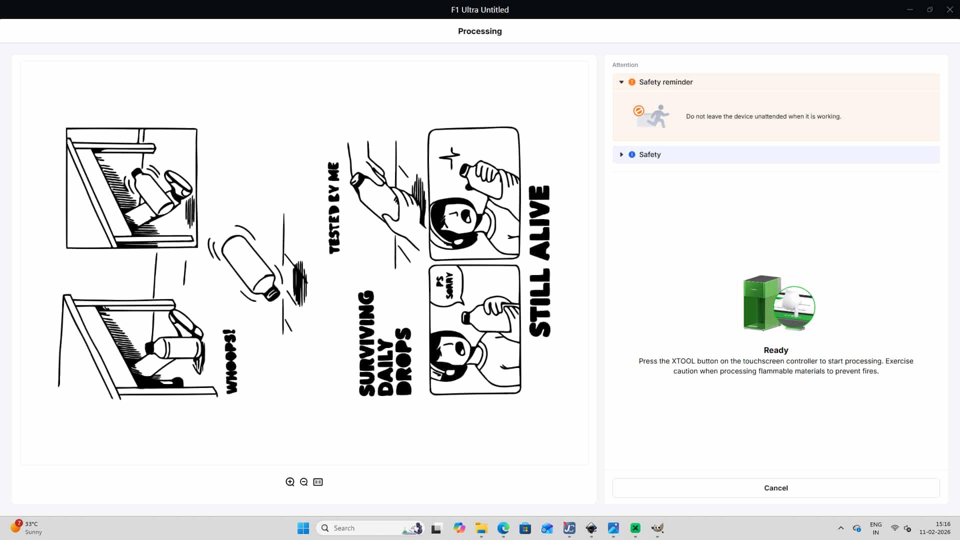
Once everything is set, press the Ready/Play button in JobControl to
send the job to the laser cutter and start cutting.
5
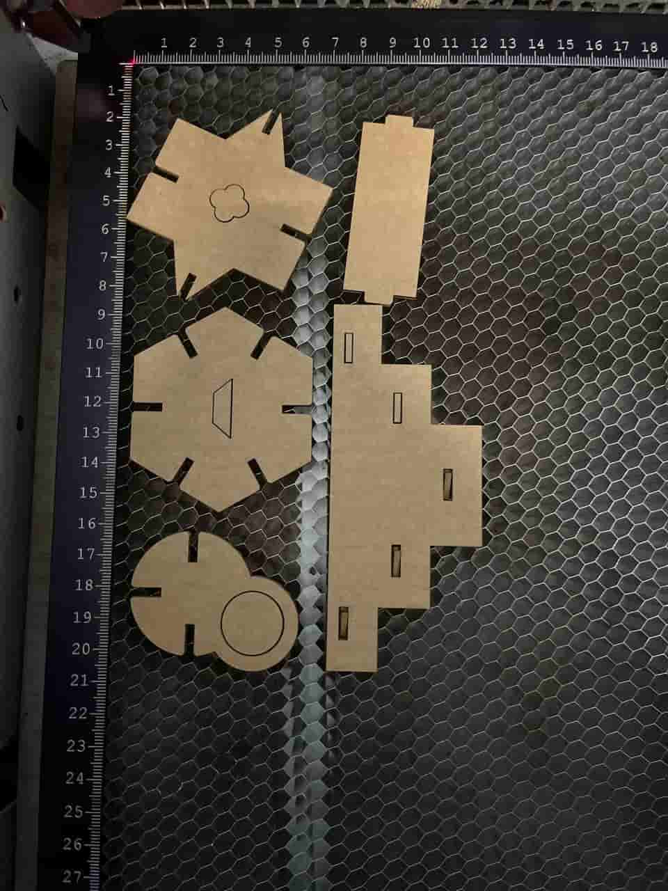
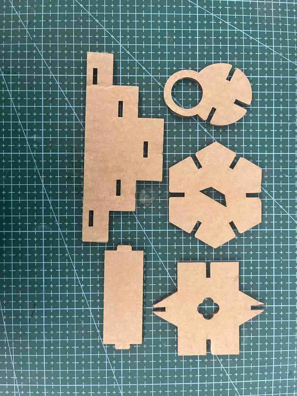
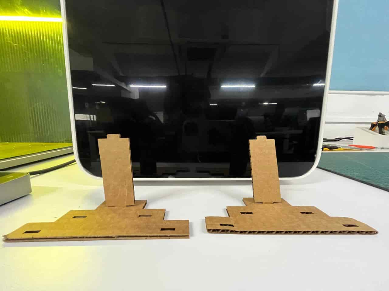
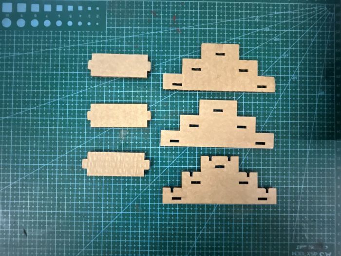
Test Cutting My Kit
First we had to do the test cut for the construction kit to check the fit. Initially I was very eager to directly make the whole kit.
I kept asking Saheen(Instructor) when I could start the final kit, but he suggested doing the test first.
Once I tested it and saw the results, I realized again how important the iterative design process is.
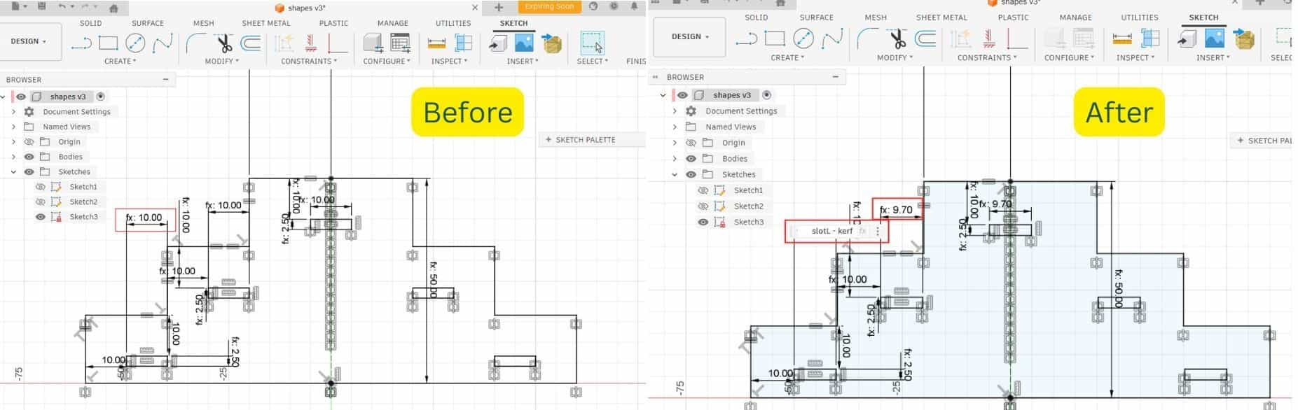
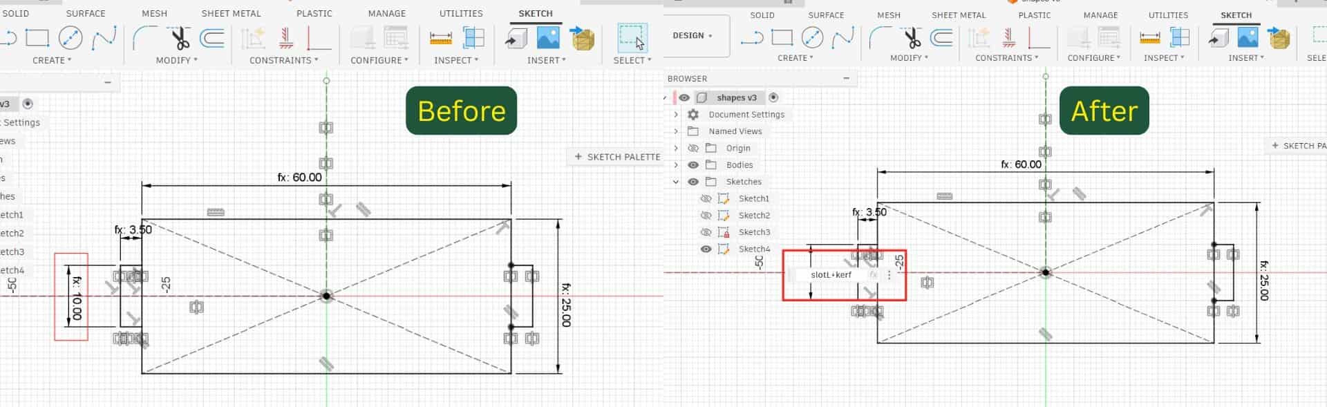
I thought that only needed to consider the kerf while setting the width values.
But in the case of a tab - slot joint, kerf must also be considered in the length as well.
Adjusted Value
Since I defined the length parameter as slotL, the slot on the step component became slotL - kerf, and the tab on the strip became slotL + kerf.
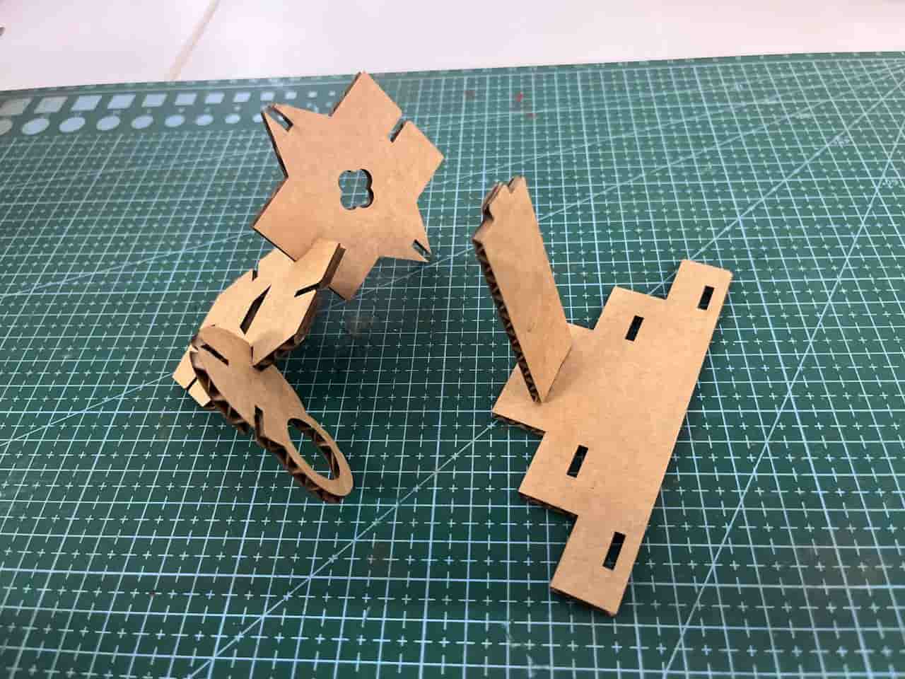
After making these corrections, I did the test again, and this time the fit came out much better.
This reminded me once again that testing before the final fabrication is very important.
6
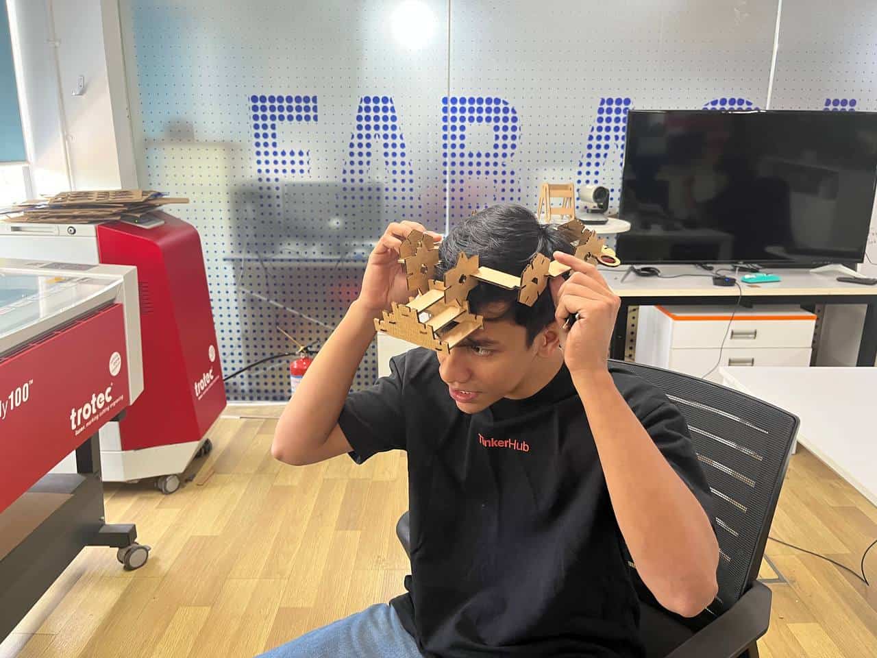
Making the whole kit
First i opened the design in Fusion. All my parts were in bodies, so converted them into components,
and then copied and pasted each component as needed. I didn't actually have any fixed requirement for the
shapes — they are mostly random, and i wanted to challenge myself to see what all I could construct from them.
There is one more thing once you done the minimium requirement of assisgnment, the remaining time you can explore.
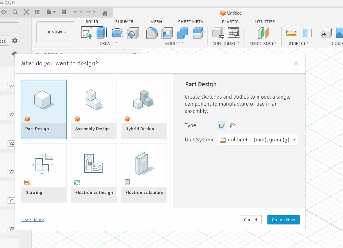
[ UPDATES: Fusion has now updated its interface into Parts, Assemble, and Hybrid.
I selected Hybrid because
it allows both part modeling and assembly in the same workspace, similar to the older Fusion version.
Otherwise, if we create in the Parts workspace, they remain bodies, and when inserted into Assemble they convert into components.]
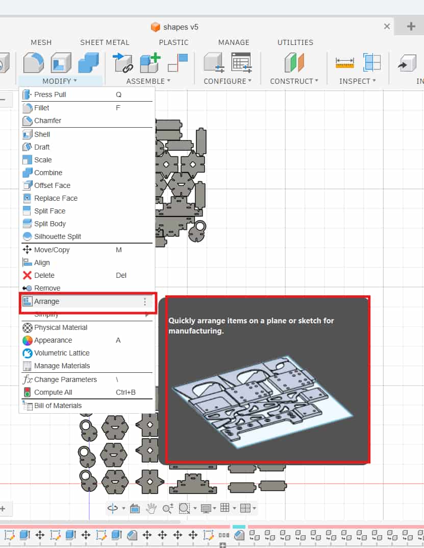
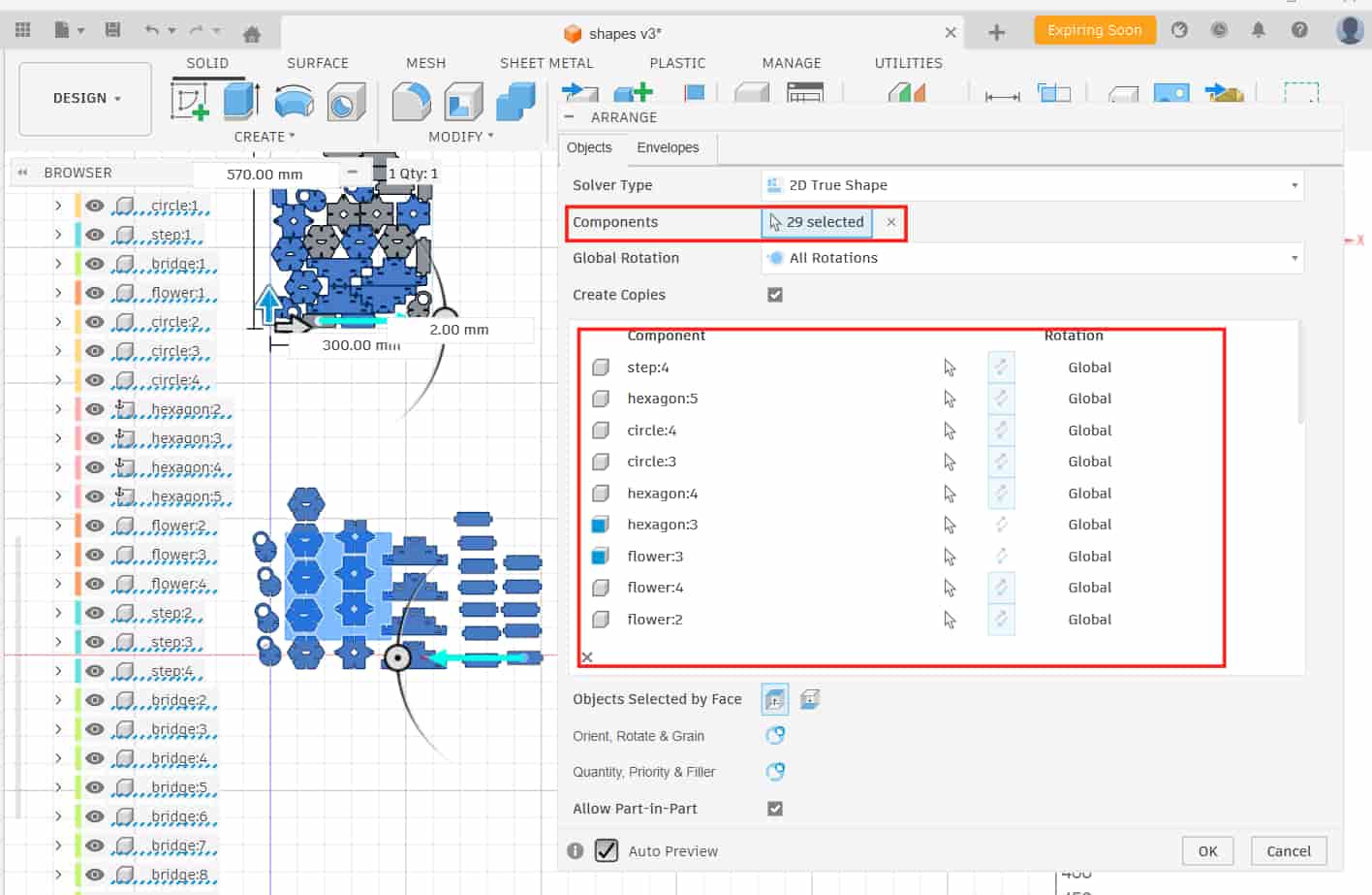
Once I had enough pieces, the next step was arranging them in a better way so that the material waste is minimal.
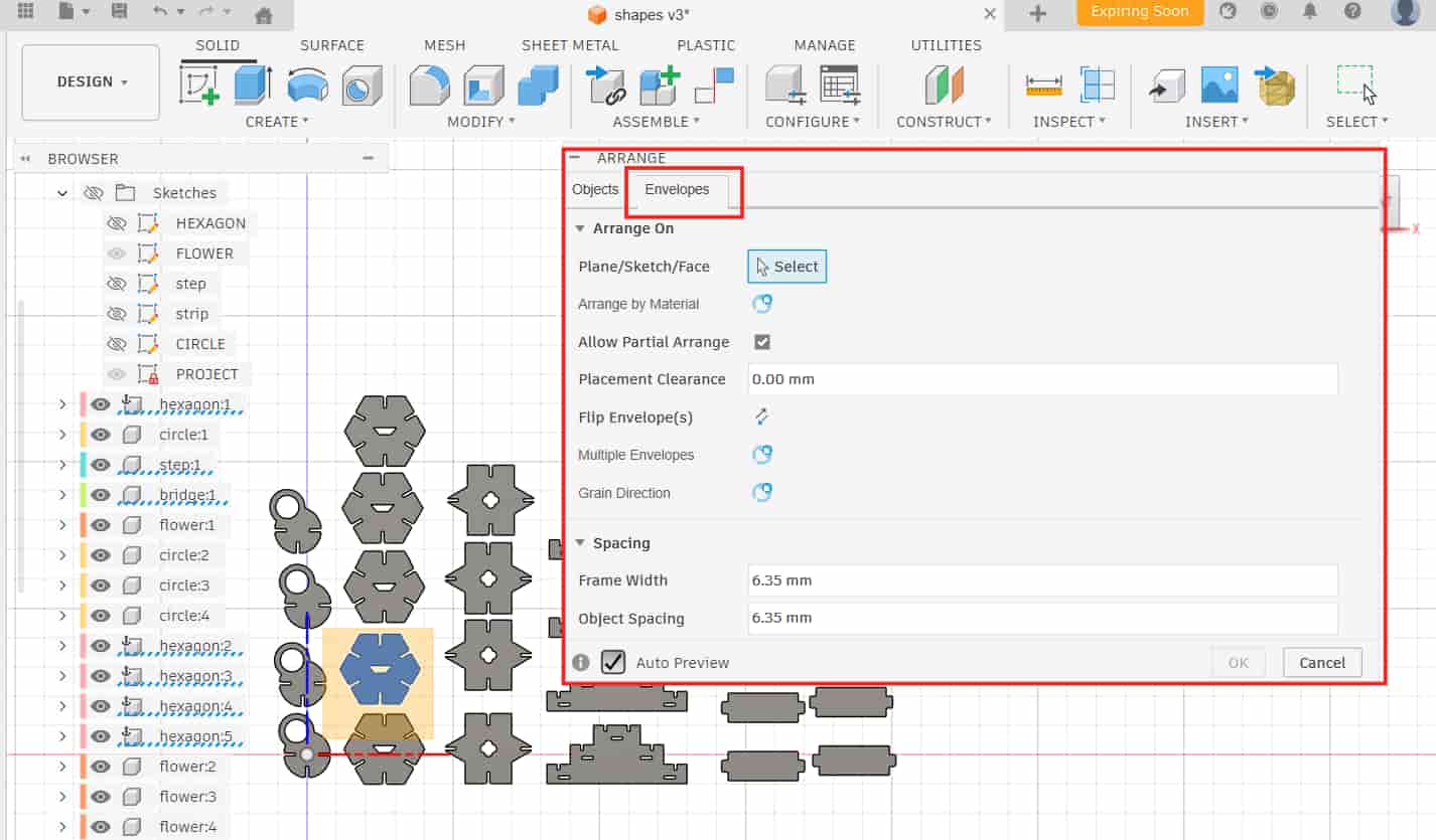
Modify >> Arrange >> Envelopes
Arrange On
I chose Arrange on Plane and selected the Front Plane.
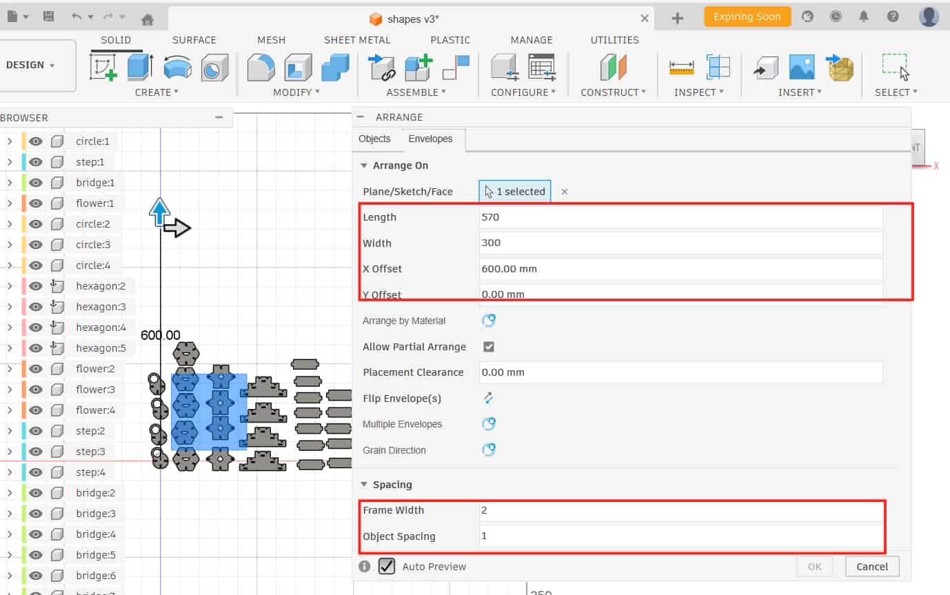
After selecting the plane, the dialog changes and shows the input
fields for length, width, and X-Y offset (offset decides the position of the layout on X and Y axis).
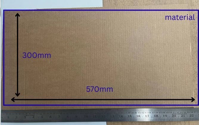
My material size was 570 mm x 300 mm, while the laser cutting working area is 610 mm x 305 mm.
Spacing
In the Spacing section, i have given values to: Frame width (sheet edge margin):2 mm
Object spacing (gap between parts): 1 mm.
Modify >> Arrange >> Object
Object
I selected all the components that needed to be arranged and clicked OK.
Fusion automatically arranged all the components.
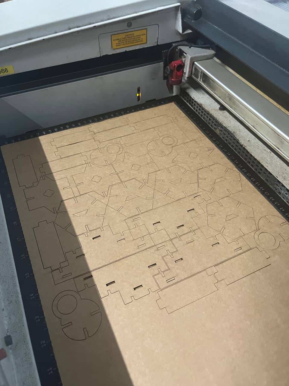
After arranging, I created a new sketch, projected the outlines of the arranged components, and exported the sketch as a DXF.
I opened it in Inkscape, resized if needed, and set the stroke color and stroke width.
Then I followed the same steps as I did for the test cutting and finally cut the whole kit.

.jpg)