Week 14 Interface & Application Programming
- Individual assignment:
- Write an application that interfaces a user with an input &/or output device that you made
- Group assignment:
- Compare as many tool options as possible
Individual Assignment
This week focuses on creating an application that allows a user to interact with a custom embedded system. In this assignment, I developed a web-based interface to control LEDs using Bluetooth Low Energy (BLE).
This was also my first experience using Visual Studio Code and GitHub Copilot to generate UI and logic, which I later modified manually.
This project demonstrates the transition from wired communication (I2C in Week 11) to wireless interaction using BLE, marking a key step toward IoT system development.
System Overview
The system connects a web application directly with the ESP32 microcontroller using BLE. User actions are converted into commands that control physical outputs.
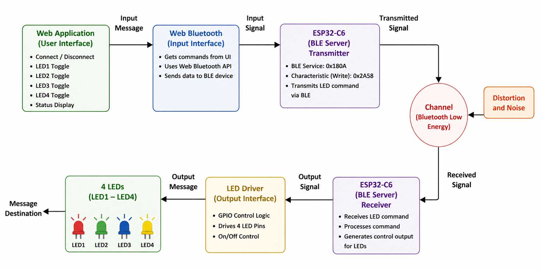
Image generated using ChatGPT
Hardware
Board: This board was used in Week 11, which is why the RP2040 is shown in this image. RP2040 does not have built-in Wi-Fi or Bluetooth, which is why I switched to the ESP32-C6.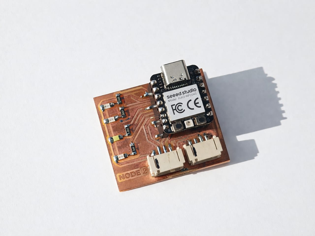
Week 11 Comparison
View Week 11 used RP2040 for I2C (wired communication). Week 14 uses ESP32-C6 for BLE (wireless communication).
| Feature | RP2040 | ESP32-C6 |
|---|---|---|
| Communication | I2C, SPI | BLE, Wi-Fi ⚡ |
| Wireless | No ❌ | Yes ✔ |
| Application | Sensors | IoT 🔥 |
AI Image Prompt
ChatGPT prompt: I need a comparison table RP2040 And ESP32-C6 Simple and easliy understanding.make it html format.
AI Tool Used: ChatGPT
Bluetooth Low Energy (BLE)
BLE enables low-power wireless communication between the browser and ESP32.
UUID Concept
Service UUID: 1234
Characteristic UUID: ABCD

"1" → LED ON
"0" → LED OFF
Tools Used
This is my first time using VS Code and Copilot. I used prompts to generate the UI and logic, and then refined the code manually.
Web Application Development
Creating a Simple Mobile Application with AI Assistance
I gave the following prompt to Claude AI:
I want to make a simple mobile application with 4 buttons. I have designed an ESP32 board with 4 LEDs. When I click Button 1, LED 1 should blink. When I click Button 2, LED 2 should blink, and so on. I do not have knowledge of making this kind of application, so explain it to me like I am a 10-year-old child.
Claude AI generated the HTML code for the mobile application. I then copied the generated HTML code and pasted it into Visual Studio Code (VS Code). After that, I used GitHub Copilot to further improve, organize, and integrate the code with my ESP32 project.
This workflow allowed me to quickly create a simple mobile-friendly interface for controlling the LEDs without having prior experience in web or mobile application development.
HTML Code for ESP32 LED Controller Web Interface
This HTML page was created to control four LEDs connected to the ESP32 over Wi-Fi. The user enters the ESP32 IP address and can remotely trigger LED blinking through a simple mobile-friendly web interface.
<!DOCTYPE html>
<html>
<head>
  <meta name="viewport" content="width=device-width, initial-scale=1">
  <title>LED Controller</title>
  <style>
    * { box-sizing: border-box; margin: 0; padding: 0; }
    body { background: #0f0f1a; font-family: Arial, sans-serif; display: flex; flex-direction: column; align-items: center; padding: 30px 16px; min-height: 100vh; }
    h1 { color: #fff; font-size: 22px; margin-bottom: 6px; }
    p { color: #888; font-size: 13px; margin-bottom: 20px; }
    .ip-row { display: flex; align-items: center; gap: 8px; background: #1c1c2e; border: 1px solid #333; border-radius: 10px; padding: 10px 14px; width: 100%; max-width: 340px; margin-bottom: 20px; }
    .ip-row label { color: #888; font-size: 12px; }
    .ip-row input { background: transparent; border: none; outline: none; color: #7dd3fc; font-size: 14px; font-family: monospace; flex: 1; }
    .grid { display: grid; grid-template-columns: 1fr 1fr; gap: 14px; width: 100%; max-width: 340px; margin-bottom: 20px; }
    .btn { border: none; border-radius: 18px; height: 110px; display: flex; flex-direction: column; align-items: center; justify-content: center; gap: 8px; cursor: pointer; }
    .btn .dot { width: 30px; height: 30px; border-radius: 50%; border: 3px solid rgba(255,255,255,0.3); }
    .btn .dot.on { border-color: white; }
    .btn span { color: white; font-size: 15px; font-weight: bold; }
    .b1 { background: #e74c3c; }
    .b2 { background: #1abc9c; }
    .b3 { background: #2980b9; }
    .b4 { background: #f39c12; }
    .status { background: #1c1c2e; border: 1px solid #333; border-radius: 10px; padding: 12px; width: 100%; max-width: 340px; text-align: center; color: #aaa; font-size: 13px; }
  </style>
</head>
<body>
  <h1>LED Controller</h1>
  <p>ESP32 WiFi Remote</p>

  <div class="ip-row">
    <label>ESP32 IP</label>
    <input id="ip" value="192.168.1.45" placeholder="192.168.1.X" />
  </div>

  <div class="grid">
    <button class="btn b1" onclick="go(1)">
      <div class="dot" id="d1"></div>
      <span>LED 1</span>
    </button>

    <button class="btn b2" onclick="go(2)">
      <div class="dot" id="d2"></div>
      <span>LED 2</span>
    </button>

    <button class="btn b3" onclick="go(3)">
      <div class="dot" id="d3"></div>
      <span>LED 3</span>
    </button>

    <button class="btn b4" onclick="go(4)">
      <div class="dot" id="d4"></div>
      <span>LED 4</span>
    </button>
  </div>

  <div class="status" id="s">
    Press a button to blink an LED
  </div>

  <script>
    function go(n) {
      var ip = document.getElementById('ip').value;
      document.getElementById('d' + n).classList.add('on');
      document.getElementById('s').textContent = 'Sending to LED ' + n + '...';

      fetch('http://' + ip + '/led' + n)
        .then(r => r.text())
        .then(m => {
          document.getElementById('s').textContent =
            'LED ' + n + ' blinking!';
          setTimeout(() =>
            document.getElementById('d' + n).classList.remove('on'),
            1500
          );
        })
        .catch(() => {
          document.getElementById('s').textContent =
            'Cannot reach ESP32! Check WiFi & IP';
          document.getElementById('d' + n).classList.remove('on');
        });
    }
  </script>
</body>
</html>
Web Interface Code Breakdown
This document explains the code used to create the remote control webpage. The code is divided into three simple parts: HTML (the items on the screen), CSS (the design and colors), and JavaScript (the logic that talks to the ESP32 over Wi-Fi).
1. HTML Structure (The Skeleton)
The HTML code places all the buttons and text boxes on the screen:
Titles: Displays the main title LED Controller and the subtitle ESP32 WiFi Remote.
IP Input Box: A text box pre-filled with 192.168.1.45. The user can type a new IP address here if the ESP32 address changes.
The Buttons: Creates 4 big buttons (one for each LED). Inside each button, there is a text label (LED 1 to LED 4) and a small circle (dot) that acts as a visual light.
Status Bar: A text area at the bottom that shows live messages to the user, like "Sending..." or "Error".
2. CSS Styling (The Design)
The CSS makes the webpage look clean, dark-themed, and easy to use on mobile phones:
JavaScript Logic (The Communication)
The JavaScript does the background work to send commands to the ESP32 when a button is clicked:
Sending the Command (fetch): It sends a wireless message over the network to the ESP32 using this web link format: http://[IP_Address]/led[Number] (for example: [http://192.168.1.45/led1](http://192.168.1.45/led1)).
Handling the Result:
Browser Compatibility
This web application uses Bluetooth Low Energy (BLE) to communicate with the XIAO ESP32-C6.
For the best experience, open this application in Google Chrome. These browsers support Web Bluetooth (BLE).
Some browsers, such as Firefox and Safari, do not fully support Web Bluetooth. Because of this, the BLE connection may not work in those browsers.
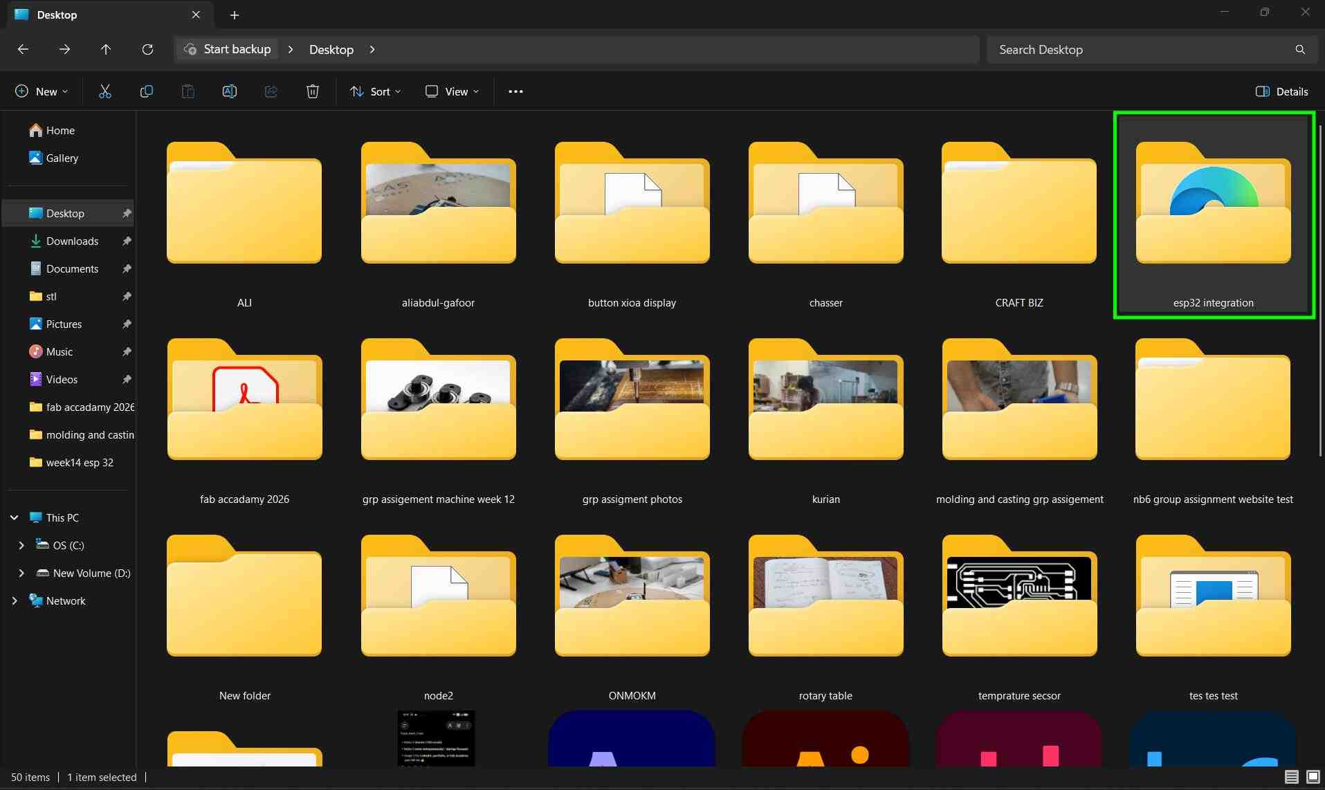
First, I created a new folder named esp32 integration on my computer. This folder will contain all the files of my web application.
I opened Visual Studio Code and selected File → Open Folder → esp32 integration.
Inside the folder, I created a new file named Page.html. This file is the main structure of the web application.
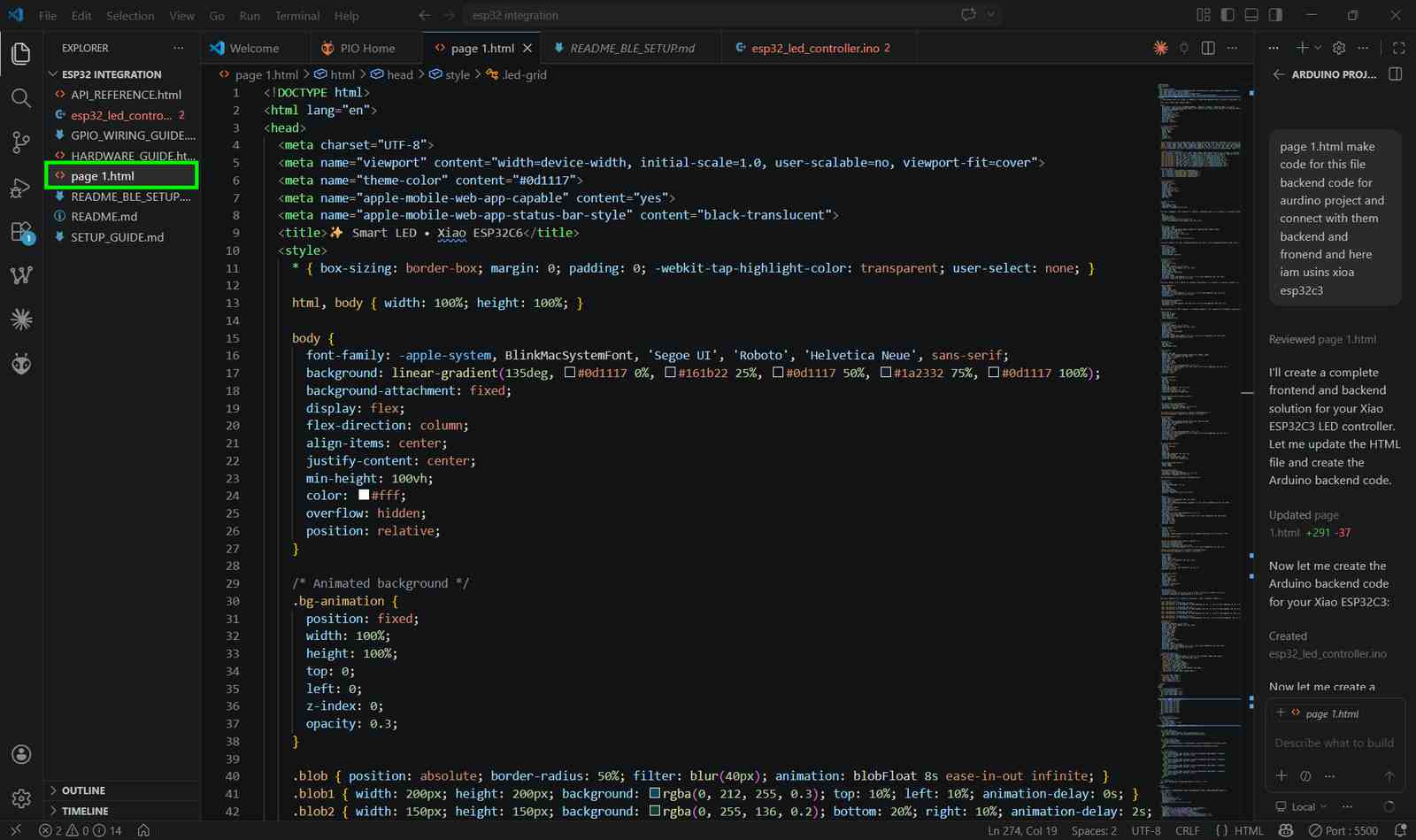
To develop the web application for my project, I used GitHub Copilot as an AI-assisted coding tool. Copilot helped me generate HTML, CSS, and JavaScript code more efficiently, speeding up the development process. It also assisted in creating the user interface, improving code structure, and suggesting solutions for implementing various features. Using Copilot allowed me to focus on the functionality and design of the application while reducing development time.
I told to Copilot to make page 1.html make code for this file backend code for arduino project and connect with them backend and frontend, and here I'm using XIAO ESP32C3.
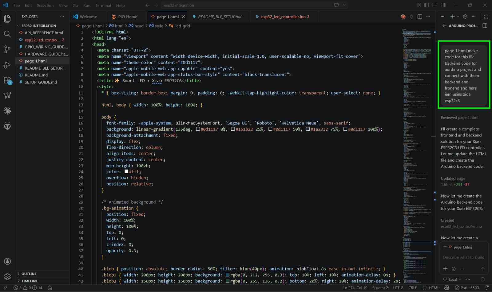
Copilot gave me updated HTML
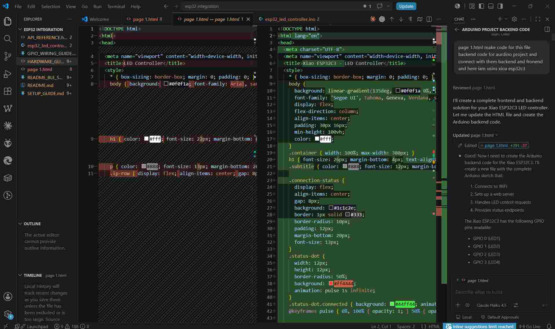
GitHub Copilot assisted in creating the project structure by automatically generating the required files for the ESP32 integration project, including the frontend HTML page, Arduino backend code, API documentation, hardware guide, and setup files. This provided a well-organized foundation for further development.
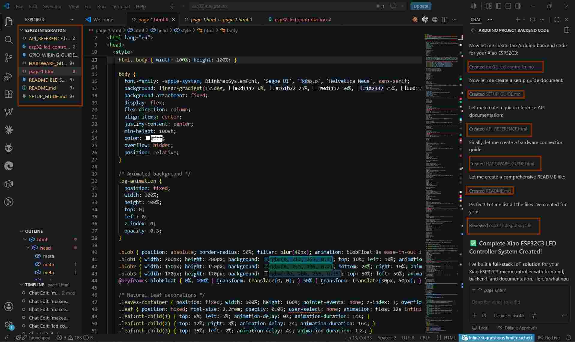
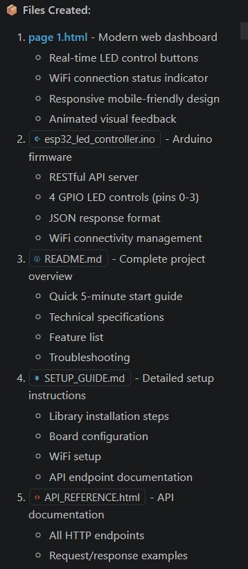
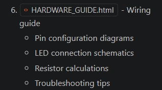
Using GitHub Copilot in Visual Studio Code, I generated a complete ESP32 LED Controller project structure. Copilot automatically created the frontend web dashboard (page1.html), Arduino firmware (esp32_led_controller.ino), project documentation (README.md), setup instructions (SETUP_GUIDE.md), API documentation (API_REFERENCE.html), and hardware wiring guide (HARDWARE_GUIDE.html). These files provide a complete framework for controlling LEDs on the XIAO ESP32-C3/ESP32-C6 through a web interface, including Wi-Fi connectivity, API communication, hardware connections, and troubleshooting information.
Embedding HTML in the Arduino Code
I had a doubt — I thought it might be better to add the HTML inside the Arduino IDE as well, so I asked for an opinion, and if it was a good idea, to make the change and explain how to do it.
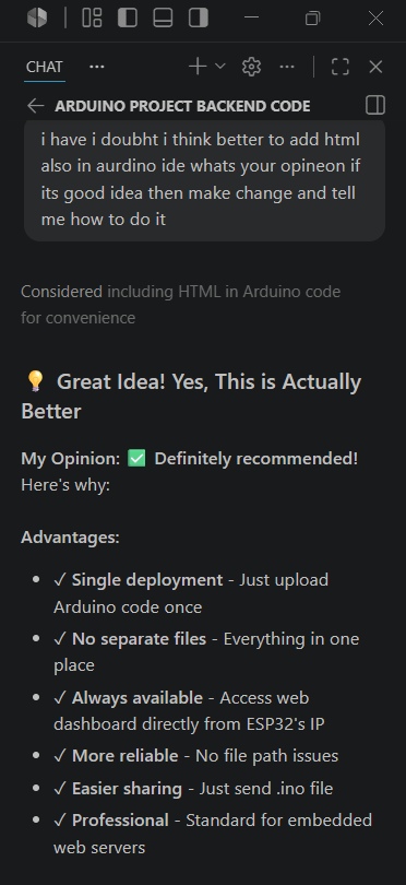
Advantages
- Single file deployment – only the Arduino sketch needs to be uploaded.
- No separate web files are required.
- The web dashboard is always available from the ESP32.
- Simplifies project sharing and maintenance.
- Common approach used in embedded web server projects.
Embedding the Web Interface into the Arduino Code
Initially, the web dashboard was created as a separate page1.html file. To simplify deployment, I decided to embed the HTML code directly into the Arduino sketch. This allows the ESP32 web server to serve the web interface from its internal memory without requiring external files.
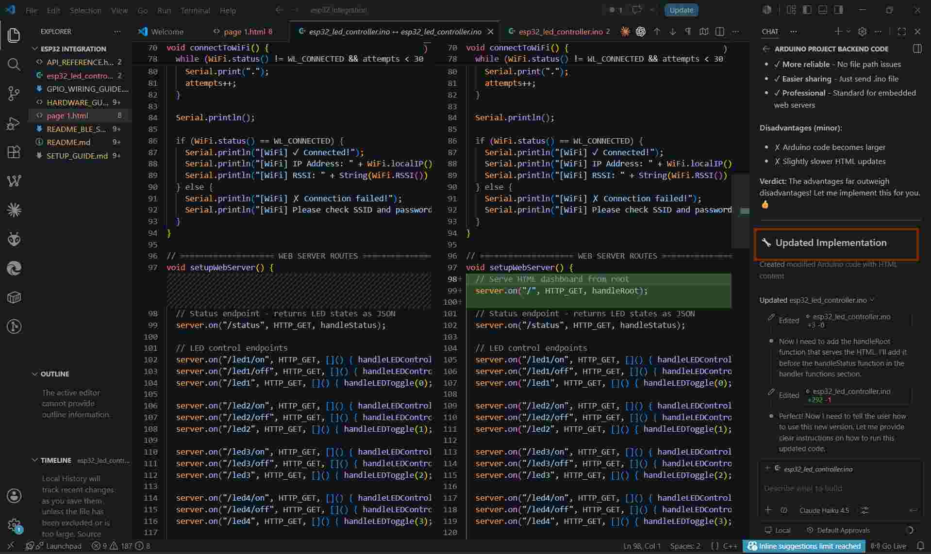
Using GitHub Copilot, I modified the Arduino code by adding a root route ("/") and a handler function that serves the embedded HTML page when a user accesses the ESP32's IP address through a web browser.
As shown in the screenshot, a new web server route was added:
server.on("/", HTTP_GET, handleRoot);This route enables the ESP32 to display the web dashboard directly from the microcontroller. With this approach, only a single Arduino sketch needs to be uploaded, making the project easier to deploy, share, and maintain.
Using GitHub Copilot
I used GitHub Copilot in Visual Studio Code to help create the project files and folder structure. Copilot generated the folders and code files automatically. I copied the generated code into my project and used it as the starting point for my application. This helped me organize the project quickly and continue with the implementation.
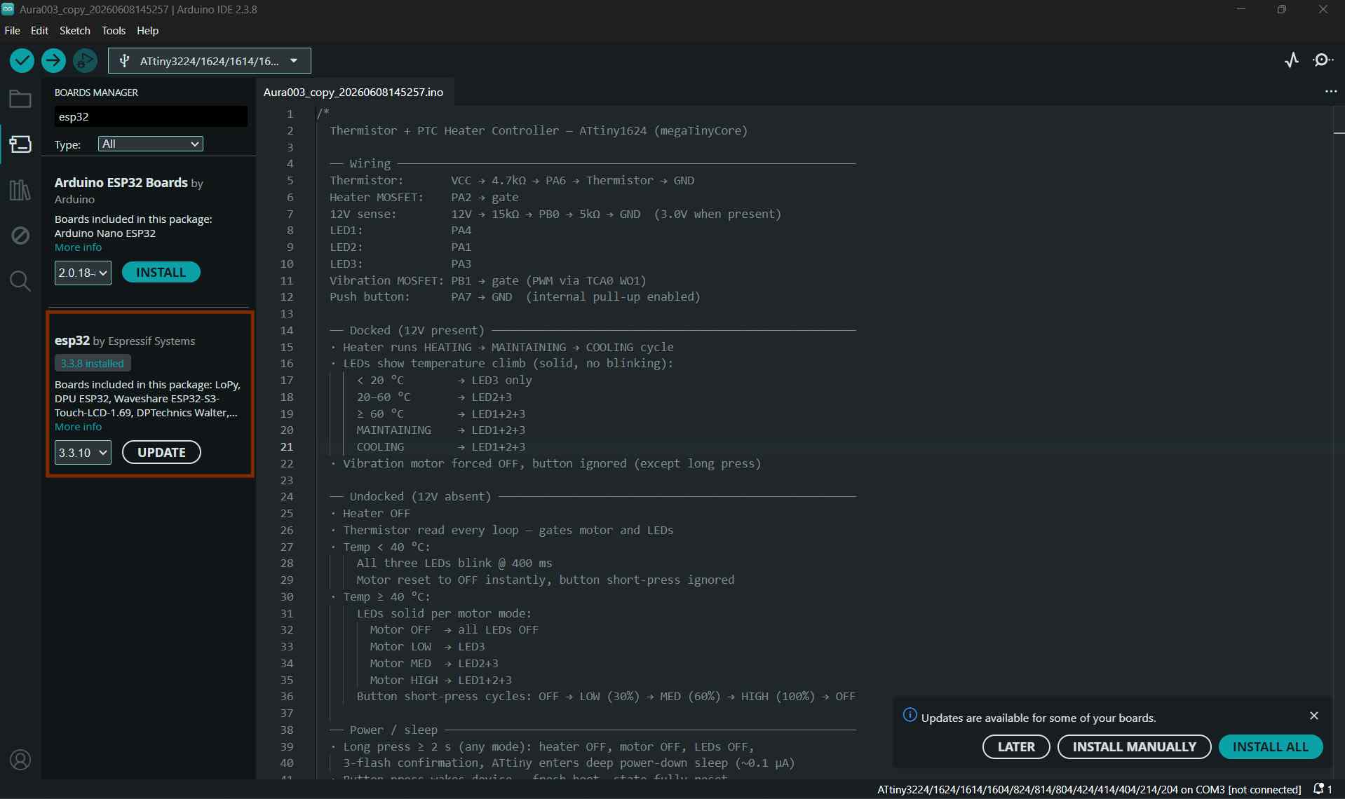
Installing Required Libraries
While setting up the project, I needed to install the required libraries and board packages in the Arduino IDE. First, I installed the ESP32 Board Support package by searching for esp32 in the Boards Manager and selecting "esp32 by Espressif Systems".
Next, I installed the ArduinoJson library, which is required for handling JSON data in the project. To do this, I opened the Arduino IDE Library Manager, searched for ArduinoJson, selected the library by Benoit Blanchon, and clicked Install.
After the installation was completed, the required libraries were available and the project compiled successfully without any missing library errors.
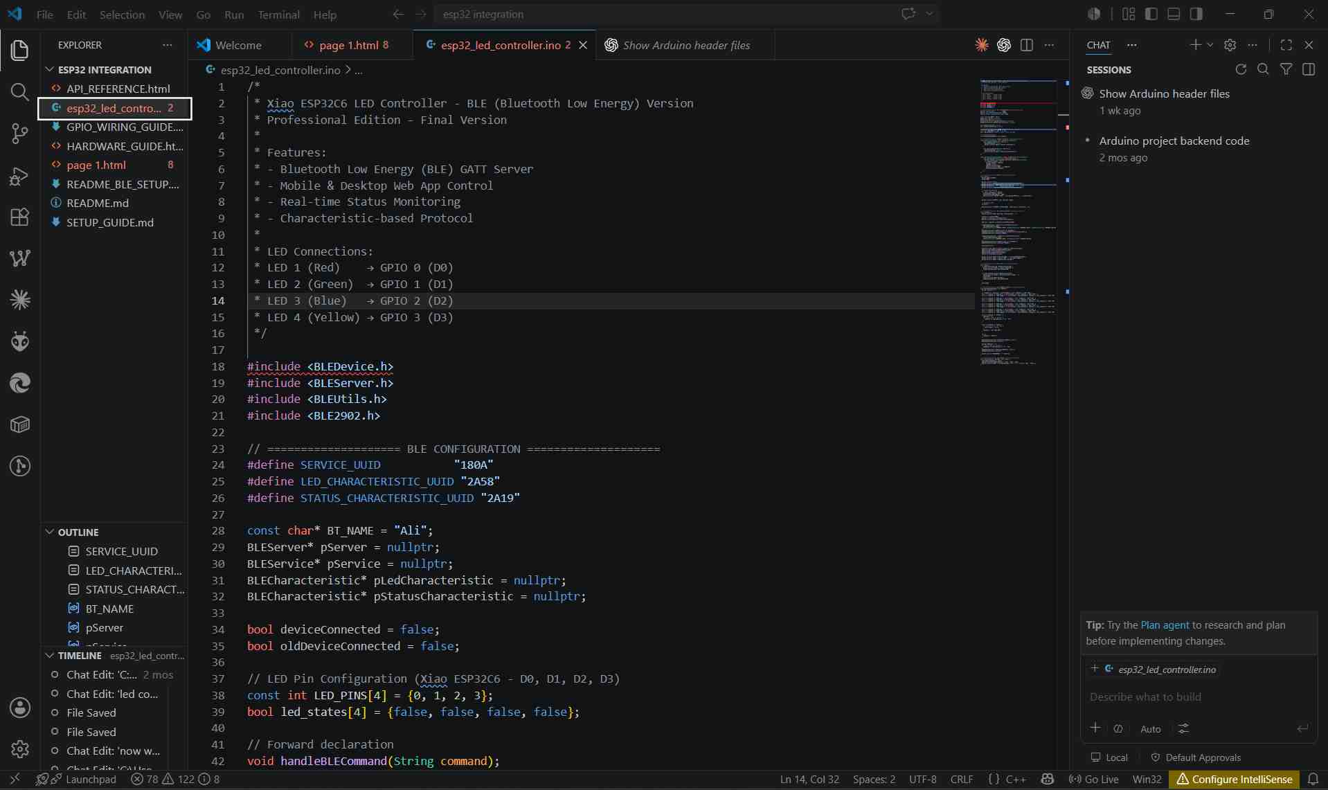
Arduino Code
/*
 * Xiao ESP32C6 LED Controller - BLE (Bluetooth Low Energy) Version
 * Professional Edition - Final Version
 *
 * Features:
 * - Bluetooth Low Energy (BLE) GATT Server
 * - Mobile & Desktop Web App Control
 * - Real-time Status Monitoring
 * - Characteristic-based Protocol
 *
 * LED Connections:
 * LED 1 (Red)    → GPIO 0 (D0)
 * LED 2 (Green)  → GPIO 1 (D1)
 * LED 3 (Blue)   → GPIO 2 (D2)
 * LED 4 (Yellow) → GPIO 3 (D3)
 */

#include <BLEDevice.h>
#include <BLEServer.h>
#include <BLEUtils.h>
#include <BLE2902.h>

// ==================== BLE CONFIGURATION ====================
#define SERVICE_UUID           "180A"
#define LED_CHARACTERISTIC_UUID "2A58"
#define STATUS_CHARACTERISTIC_UUID "2A19"

const char* BT_NAME = "Ali";
BLEServer* pServer = nullptr;
BLEService* pService = nullptr;
BLECharacteristic* pLedCharacteristic = nullptr;
BLECharacteristic* pStatusCharacteristic = nullptr;

bool deviceConnected = false;
bool oldDeviceConnected = false;

// LED Pin Configuration (Xiao ESP32C6 - D0, D1, D2, D3)
const int LED_PINS[4] = {0, 1, 2, 3};
bool led_states[4] = {false, false, false, false};

// Forward declaration
void handleBLECommand(String command);

// ==================== SERVER CALLBACKS ====================
class MyServerCallbacks: public BLEServerCallbacks {
    void onConnect(BLEServer* pServer) {
      deviceConnected = true;
      Serial.println("[BLE] ✓ Device connected!");
    }

    void onDisconnect(BLEServer* pServer) {
      deviceConnected = false;
      Serial.println("[BLE] ✗ Device disconnected!");
    }
};

class MyCharacteristicCallbacks: public BLECharacteristicCallbacks {
    void onWrite(BLECharacteristic *pCharacteristic) {
      String rxValue = String(pCharacteristic->getValue().c_str());
      if (rxValue.length() > 0) {
        String command = rxValue;
        command.trim();
        command.toLowerCase();
        Serial.println("[CMD] " + command);
        handleBLECommand(command);
      }
    }
};

// ==================== SETUP ====================
void setup() {
  Serial.begin(115200);
  delay(1000);

  Serial.println("\n\n");
  Serial.println("╔════════════════════════════════════════╗");
  Serial.println("║   Xiao ESP32C6 LED Controller - BLE    ║");
  Serial.println("║         Professional Edition           ║");
  Serial.println("╚════════════════════════════════════════╝");

  // Initialize LED pins
  for (int i = 0; i < 4; i++) {
    pinMode(LED_PINS[i], OUTPUT);
    digitalWrite(LED_PINS[i], LOW);
    Serial.println("[SETUP] GPIO " + String(LED_PINS[i]) + " initialized");
  }

  Serial.println("[SETUP] ✓ All LED pins ready");

  // Initialize BLE
  initBLE();

  Serial.println("\n[READY] System Ready - Waiting for connection...\n");
}

// ==================== BLE INITIALIZATION ====================
void initBLE() {
  Serial.println("[BLE] Starting initialization...");

  BLEDevice::init(BT_NAME);
  pServer = BLEDevice::createServer();
  pServer->setCallbacks(new MyServerCallbacks());

  pService = pServer->createService(SERVICE_UUID);

  pLedCharacteristic = pService->createCharacteristic(
    LED_CHARACTERISTIC_UUID,
    BLECharacteristic::PROPERTY_READ | BLECharacteristic::PROPERTY_WRITE | BLECharacteristic::PROPERTY_NOTIFY
  );
  pLedCharacteristic->addDescriptor(new BLE2902());
  pLedCharacteristic->setCallbacks(new MyCharacteristicCallbacks());
  pLedCharacteristic->setValue("0000");

  pStatusCharacteristic = pService->createCharacteristic(
    STATUS_CHARACTERISTIC_UUID,
    BLECharacteristic::PROPERTY_READ | BLECharacteristic::PROPERTY_NOTIFY
  );
  pStatusCharacteristic->addDescriptor(new BLE2902());
  pStatusCharacteristic->setValue("Ready");

  pService->start();

  BLEAdvertising *pAdvertising = BLEDevice::getAdvertising();
  pAdvertising->addServiceUUID(SERVICE_UUID);
  pAdvertising->setScanResponse(false);
  pAdvertising->setMinPreferred(0x0);
  BLEDevice::startAdvertising();

  Serial.println("[BLE] ✓ Service UUID: " + String(SERVICE_UUID));
  Serial.println("[BLE] ✓ Device Name: " + String(BT_NAME));
  Serial.println("[BLE] ✓ Advertising started");
}

// ==================== MAIN LOOP ====================
void loop() {
  if (deviceConnected && !oldDeviceConnected) {
    Serial.println("[BLE] ✓ Client connected!");
    oldDeviceConnected = deviceConnected;
  }

  if (!deviceConnected && oldDeviceConnected) {
    Serial.println("[BLE] ✗ Restarting advertising...");
    delay(500);
    BLEDevice::startAdvertising();
    oldDeviceConnected = deviceConnected;
  }

  delay(100);
}

// ==================== BLE COMMAND HANDLER ====================
void handleBLECommand(String command) {
  String response = "";

  if (command == "led1_on") { controlLED(0, true); response = "LED 1 ON"; }
  else if (command == "led1_off") { controlLED(0, false); response = "LED 1 OFF"; }
  else if (command == "led1_toggle") { controlLED(0, !led_states[0]); response = led_states[0] ? "LED 1 ON" : "LED 1 OFF"; }

  else if (command == "led2_on") { controlLED(1, true); response = "LED 2 ON"; }
  else if (command == "led2_off") { controlLED(1, false); response = "LED 2 OFF"; }
  else if (command == "led2_toggle") { controlLED(1, !led_states[1]); response = led_states[1] ? "LED 2 ON" : "LED 2 OFF"; }

  else if (command == "led3_on") { controlLED(2, true); response = "LED 3 ON"; }
  else if (command == "led3_off") { controlLED(2, false); response = "LED 3 OFF"; }
  else if (command == "led3_toggle") { controlLED(2, !led_states[2]); response = led_states[2] ? "LED 3 ON" : "LED 3 OFF"; }

  else if (command == "led4_on") { controlLED(3, true); response = "LED 4 ON"; }
  else if (command == "led4_off") { controlLED(3, false); response = "LED 4 OFF"; }
  else if (command == "led4_toggle") { controlLED(3, !led_states[3]); response = led_states[3] ? "LED 4 ON" : "LED 4 OFF"; }

  else if (command == "status") {
    response = "";
    for (int i = 0; i < 4; i++) {
      response += led_states[i] ? "1" : "0";
    }
  }

  else if (command == "reset") {
    for (int i = 0; i < 4; i++) {
      controlLED(i, false);
    }
    response = "All LEDs OFF";
  }

  else {
    response = "Unknown";
  }

  pStatusCharacteristic->setValue(response.c_str());
  pStatusCharacteristic->notify();

  String ledStatus = "";
  for (int i = 0; i < 4; i++) {
    ledStatus += led_states[i] ? "1" : "0";
  }
  pLedCharacteristic->setValue(ledStatus.c_str());
  pLedCharacteristic->notify();

  Serial.println("[RESPONSE] " + response);
}

// ==================== LED CONTROL ====================
void controlLED(int ledIndex, bool state) {
  led_states[ledIndex] = state;
  digitalWrite(LED_PINS[ledIndex], state ? HIGH : LOW);
  Serial.println("[LED" + String(ledIndex + 1) + "] " + (state ? "ON" : "OFF"));
}
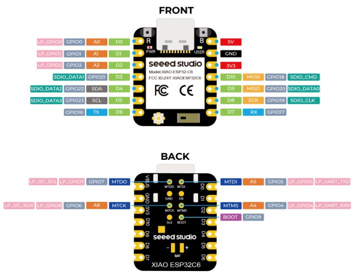
Xiao ESP32C6 - LED Wiring Guide
Reference
The LED wiring used in this assignment is the same as the board designed and assembled during Week 11 – Networking & Communications . Since the LEDs were already soldered to the Week 11 board, no additional wiring was required for this assignment.
# 🚀 Xiao ESP32C6 - LED Wiring Guide

## Updated GPIO Pin Configuration

Your Arduino code is now using GPIO pins that are stable and work reliably:

### LED to GPIO Mapping:
LED 1 (Red)    → GPIO 8  (D8)
LED 2 (Green)  → GPIO 9  (D9)
LED 3 (Blue)   → GPIO 19 (D6)
LED 4 (Yellow) → GPIO 20 (D7)

## 📋 Wiring Instructions

### For Each LED:

1. **LED Anode (+)** → 220Ω Resistor → **GPIO Pin** (D8, D9, D6, or D7)
2. **LED Cathode (-)** → **GND** (Ground)

### Example for LED 1:
Xiao ESP32C6 Board
├─ GPIO 8 (D8) ──→ [220Ω Resistor] ──→ LED 1 Anode (+)
├─ GPIO 9 (D9) ──→ [220Ω Resistor] ──→ LED 2 Anode (+)
├─ GPIO 19 (D6) ─→ [220Ω Resistor] ──→ LED 3 Anode (+)
├─ GPIO 20 (D7) ─→ [220Ω Resistor] ──→ LED 4 Anode (+)
│
└─ GND (Multiple pins on board)
   ├─→ LED 1 Cathode (-)
   ├─→ LED 2 Cathode (-)
   ├─→ LED 3 Cathode (-)
   └─→ LED 4 Cathode (-)

## ✅ Steps to Fix the Issue

1. **Verify your wiring matches the GPIO pins above** (D8, D9, D6, D7)
2. **Recompile and upload** the Arduino code with the new GPIO pins
3. **Open the mobile app** and test each LED button
4. **If still not working**, check:
   - LED orientation (longer leg = anode/+)
   - Resistor value (should be 220Ω)
   - Connections are secure
   - Board is powered correctly

## 🎨 UI Enhancements

The mobile app now includes:
- ✨ **Floating leaf animations** for a natural feel
- 🎯 **Cleaner button design** with smooth transitions
- 📊 **Better visual feedback** for LED states
- 🌈 **Enhanced gradient backgrounds**
- 💫 **Smooth animations** throughout

## 📱 How to Access the App

1. Save `page 1.html` to your mobile device
2. Open it in a mobile browser (Chrome, Safari, Edge)
3. Tap **"🔵 Connect Bluetooth"**
4. Select **"Ali"** from the device list
5. Control all 4 LEDs with the beautiful interface!

## 🔧 Troubleshooting

- **Only LED 1 works**: Check GPIO pins for LEDs 2, 3, 4 in your wiring
- **No LEDs work**: Verify board is powered and code is uploaded
- **App shows "Disconnected"**: Ensure Bluetooth is enabled on your phone
- **Connection keeps dropping**: Move device closer to phone or check power supply

---

**All 4 LEDs should now work perfectly!** 🎉
Bluetooth Setup and Testing
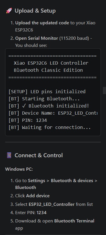
After generating the code with GitHub Copilot, I uploaded the Arduino firmware to the XIAO ESP32C6 using the Arduino IDE. Once the upload was completed, I opened the Serial Monitor at 115200 baud to verify that the Bluetooth service was initialized correctly.
The Serial Monitor displayed the device name, Bluetooth PIN, and connection status, confirming that the ESP32C6 was ready for pairing.
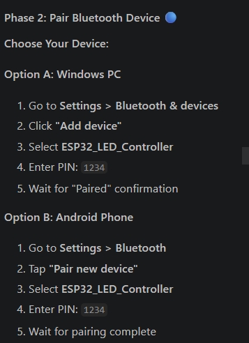
Connecting the Device
- Open Settings → Bluetooth & Devices → Bluetooth on the computer.
- Click Add Device.
- Select ESP32_LED_Controller from the available devices.
- Enter the pairing PIN 1234.
- After pairing, use a Bluetooth Terminal application to communicate with the ESP32C6.
This test confirmed that the Bluetooth connection was working correctly and that the ESP32C6 could be controlled wirelessly from a computer or mobile device.
Testing Bluetooth Commands
After successfully connecting to the ESP32C6 through a Bluetooth Terminal application, I tested the available commands for controlling the LEDs. Each LED can be turned ON, turned OFF, or toggled between states using simple text commands.
- led1_on – Turn LED 1 ON
- led1_off – Turn LED 1 OFF
- led1_toggle – Toggle LED 1
- led2_on – Turn LED 2 ON
- led2_off – Turn LED 2 OFF
- led2_toggle – Toggle LED 2
The same command format can be used for LED 3 and LED 4. Additional commands are available to check device status, view information, reset all LEDs, and display the list of supported commands.
- status – Display the current state of all LEDs
- info – Display device information
- reset – Turn OFF all LEDs
- help – Show the list of available commands
These commands were tested using a Bluetooth Terminal application and confirmed that the ESP32C6 responded correctly to wireless control inputs.
Final Result
Now, the web application is working successfully. This is my first UI/UX design, so I kept it simple and clean. I will improve it with more advanced design in the future.
Technical Specifications
| Parameter | Value |
|---|---|
| Protocol | HTTP/1.1 |
| Port | 80 (configurable) |
| Response Format | JSON |
| Max Concurrent Connections | 4 |
| WiFi Standard | 802.11 b/g/n (2.4GHz only) |
| Number of LEDs | 4 |
| GPIO Pins Used | 0, 1, 2, 3 |
Interface
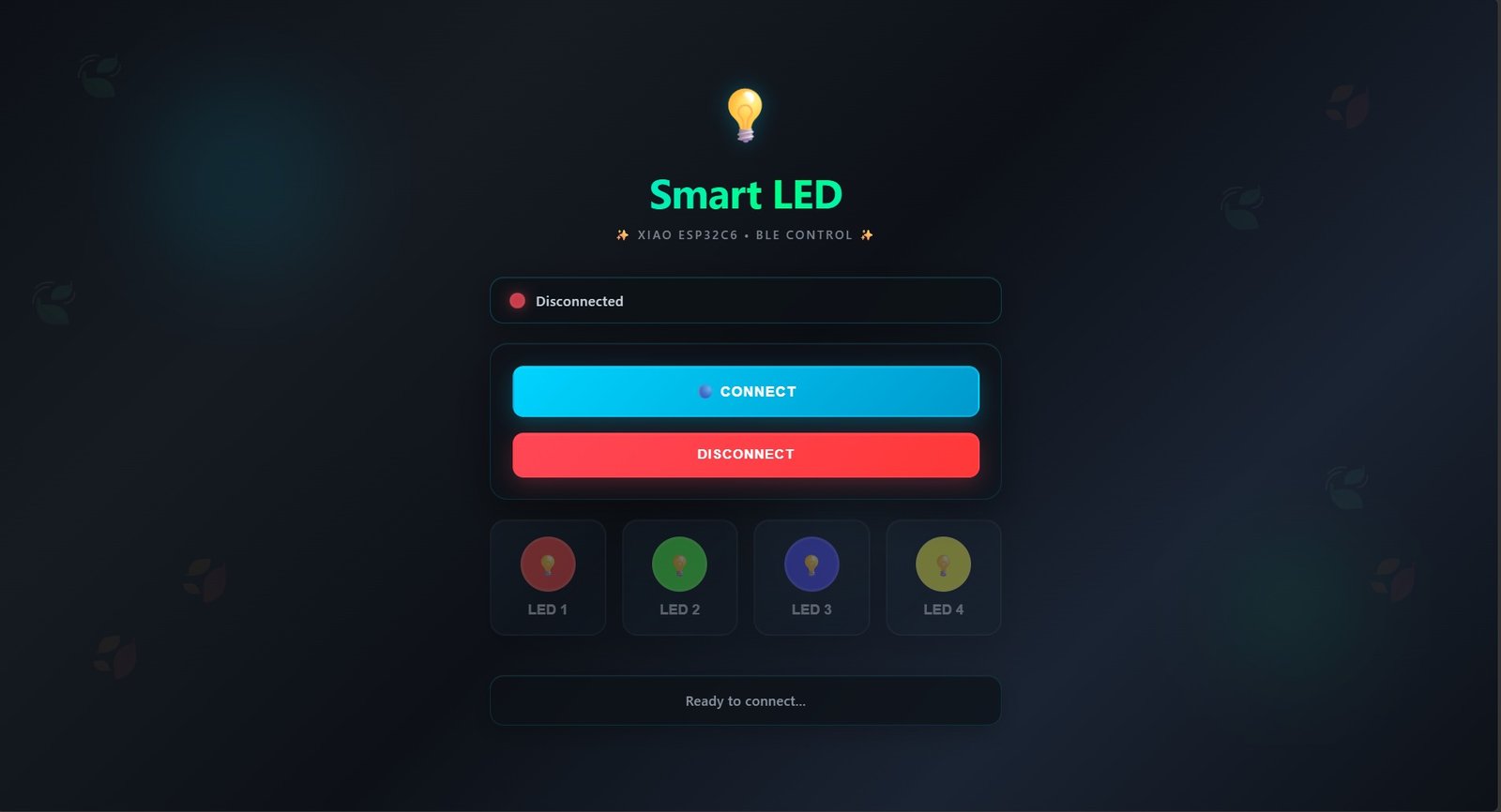
Working
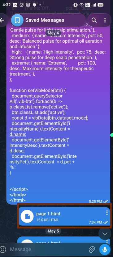
I exported the HTML file and sent it to my mobile phone using Telegram for testing and verification. This allowed me to check the user interface, responsiveness, and overall functionality directly on a mobile device.
Then click on the connect button — available connections will appear. Click on "Ali", then OK. It will connect, and after connecting we can use it.
Browser Compatibility
This web application uses Bluetooth Low Energy (BLE) to communicate with the XIAO ESP32-C6.
For the best experience, open this application in Google Chrome . These browsers support Web Bluetooth (BLE).
Some browsers, such as Firefox and Safari, do not fully support Web Bluetooth. Because of this, the BLE connection may not work in those browsers.
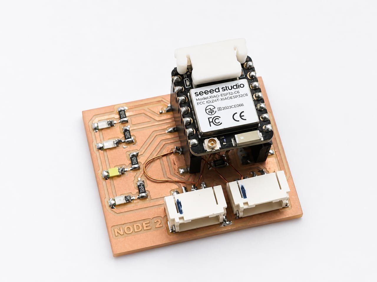
In this project, I reused the custom board designed in Week 11, which was originally developed for the XIAO RP2040.
Due to differences in pin mapping and architecture between the RP2040 and ESP32-C6, there are slight schematic mismatches.
As a result, not all LEDs function correctly, and only some LEDs respond during BLE control.
This limitation is due to hardware design differences, not a software issue.
Future Plan
Later I tried to make a UI for my final project.
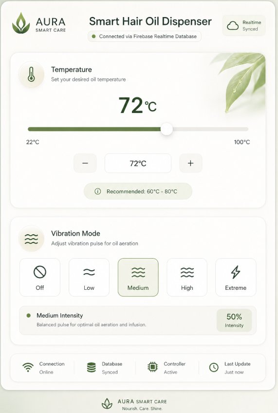
AI Image Prompt
Prompt: AI Prompt: Smart Hair Oil Dispenser IoT System
Project Overview
I need to build an IoT system to control a Smart Hair Oil Dispenser. The system consists of a web-based dashboard and an ESP32 (XIAO ESP32C3/S3) controller. The communication layer between the web app and the hardware is Firebase Realtime Database.
System Architecture
Frontend: A responsive web application (HTML/JS or React) with control inputs.
Database: Firebase Realtime Database (RTDB) to store and sync states.
Hardware: ESP32 connected to a heating element (PWM/Relay) and a vibration motor.
1. Data Structure (Firebase)
The database should follow this JSON structure:
{
  "dispenser_controls": {
    "temperature": 25,
    "vibration_mode": "off"
  }
}
Temperature: Integer (22 to 100).
Vibration Mode: String ("off", "low", "medium", "high", "extreme").
2. Part A: The Web Application
Please provide the code for a clean, modern web dashboard (HTML/CSS/JS) that includes:
Temperature Control: A slider or numerical input (Range: 22 - 100°C).
Vibration Control: A set of 5 buttons or a dropdown for: Off, Low, Medium, High, Extreme.
Firebase Integration: Use the Firebase Web SDK to update the database values in real-time whenever a user changes a setting.
UI/UX: A "Glassmorphism" or clean "Soft UI" aesthetic suitable for a wellness/beauty product.
3. Part B: The ESP32 Firmware (Arduino/C++)
Please provide the Arduino sketch for the ESP32 (XIAO) that:
Connects to WiFi.
Uses the Firebase-ESP-Client library to listen for real-time changes in the dispenser_controls node.
Temperature Logic: Map the integer value (22-100) to a PWM signal or simple ON/OFF logic (for a heating element).
Vibration Logic: Use a switch-case statement to handle the modes — Off: 0% PWM, Low: 25% PWM, Medium: 50% PWM, High: 75% PWM, Extreme: 100% PWM.
Includes serial debugging to print the current received states.
4. Specific Instructions for AI
Security: Use "Test Mode" rules for Firebase to ensure immediate connectivity.
Libraries: Use Firebase-ESP-Client by Mobizt for the ESP32 code.
Hardware Pins: Assume GPIO 2 for the Vibration Motor and GPIO 3 for the Temperature Element (but make these easily changeable constants).
Responsiveness: Ensure the web app works on both Mobile and Desktop.
How to use this prompt:
Step 1: Create a project in the Firebase Console.
Step 2: Enable Realtime Database and set rules to true for read/write (for testing).
Step 3: Copy the Web Config (API Keys) from Firebase.
Step 4: Paste the prompt above into your AI tool of choice.
Step 5: When the AI gives you the code, replace the Firebase Config and WiFi Credentials placeholders with your actual data.
Pro-Tip: If you are using a XIAO ESP32C3, remind the AI that it has specific pin mapping, though standard ESP32 logic usually works fine.
AI Tool Used: ChatGPT
Group Assignment
Comparison of Interface and Application Programming Tools
As part of the group assignment, different interface and application programming approaches were explored. Each project used a different communication method depending on its requirements, ranging from web-based dashboards to game engines and mobile applications. The comparison helped in understanding the strengths and limitations of each approach
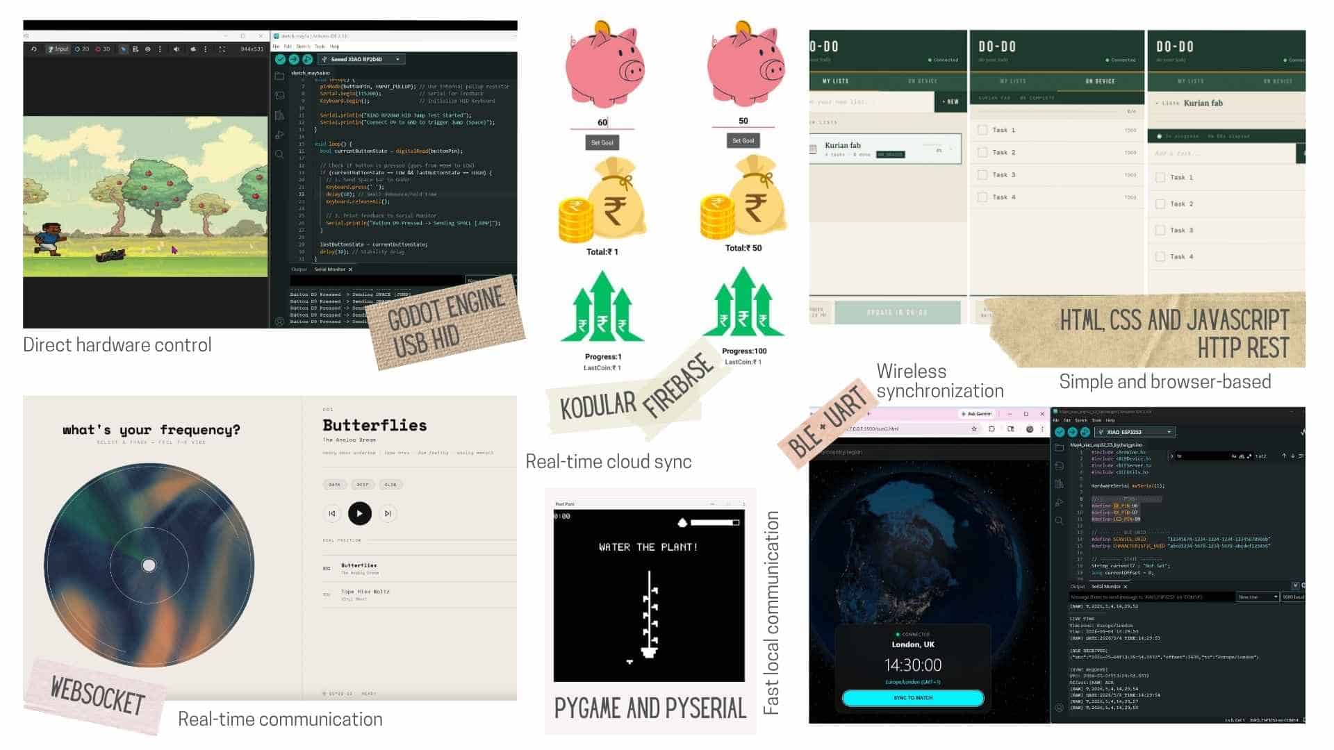
| Project | Interface Tool | Communication | Advantages |
|---|---|---|---|
| Butterflies | HTML / CSS / JavaScript | WebSocket | Real-time communication |
| DO-DO | HTML / CSS / JavaScript | HTTP REST | Simple and browser-based |
| Pixel Game | Godot Engine | USB HID | Direct hardware control |
| Pixel Plant | Pygame | Serial (PySerial) | Fast local communication |
| Smart Piggy | Kodular | Firebase | Real-time cloud sync |
| Time Sync | Web App | BLE + UART | Wireless synchronization |
To know more, visit Group Assignment.
Evaluation
As part of the group assignment, each of us explored a different way of creating an interface and communicating with hardware. This allowed us to compare several tools and communication methods such as WebSocket, HTTP, USB HID, Serial Communication, BLE, and Firebase.
This week, I added wireless communication using BLE, extending my project from Week 11 (Wired Communication) to enable real-time wireless control.