week 09 Input Devices
Objectives
Group assignment: probe an input device's analog levels and digital signals
Individual assignment: measure something: add a sensor to a microcontroller board that you have designed and read it
Group assignment
In group assignment, we focused on analyzing input devices by probing their analog and digital signals using an oscilloscope. We tested the INMP441 MEMS microphone, which produces a digital signal, and the PS2 joystick module, which outputs an analog signal. The oscilloscope was used to measure and visualize voltage variations from both sensors.
To know more, visit Group Assignment .
Input Devices
Sensors
Sensors are devices that detect and measure changes in their surrounding environment and convert them into electrical signals. These changes can be in the form of light, temperature, pressure, motion, humidity, sound, chemical composition, or other physical properties. Sensors play a crucial role in modern technology by enabling automated systems, data collection, and real-time monitoring.
100k Thermistor
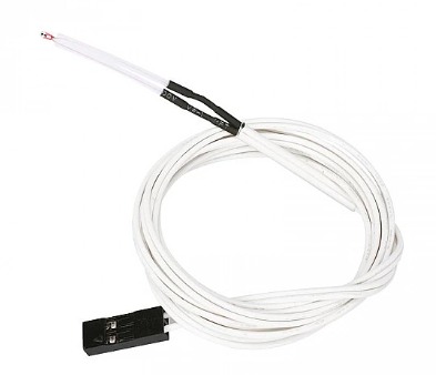
A 100kΩ thermistor is a temperature-sensitive resistor whose resistance decreases as temperature rises (NTC). Commonly featuring a Beta value of 3950, it is the standard sensor used to measure hotend and heatbed temperatures in 3D printers
DS18B20 – Digital Temperature Sensor
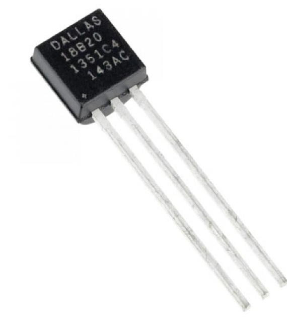
The DS18B20 is a digital thermometer that provides 9 to 12-bit Celsius temperature measurements and communicates over a 1-Wire bus, requiring only one data line (and ground) to connect to a central microprocessor. It is highly versatile due to its unique 64-bit serial code, which allows multiple sensors to function on the same bus, and its ability to derive power directly from the data line
ATtiny1624
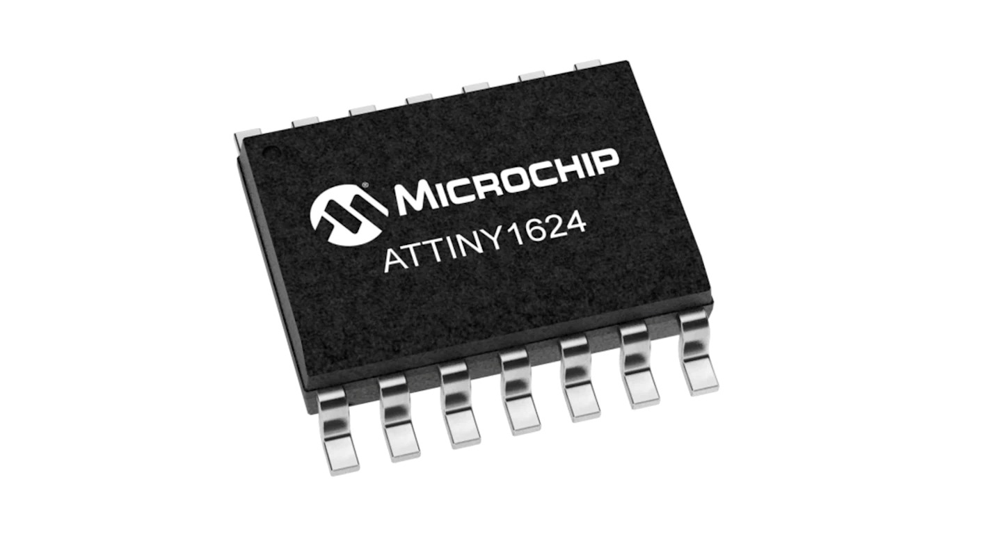
ATtiny1624 is a compact and powerful 8-bit microcontroller from Microchip's tinyAVR 2-series, designed for embedded systems and sensor-based projects.
Key Features
Why It's Good for my Project
Resistor: 4.7kΩ (pull-up resistor for DS18B20)

The 4.7kΩ resistor helps the DS18B20 communicate correctly and reliably with the microcontroller.
CAPACITIVE SENSING
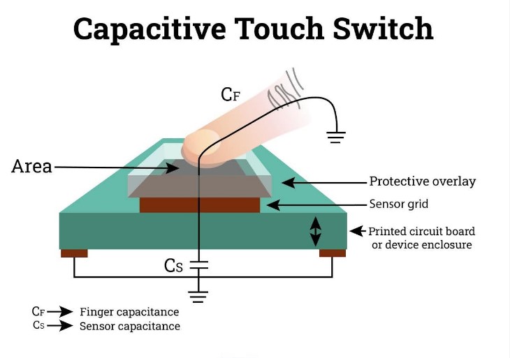 Image source
Capacitive sensors detect objects by measuring changes in capacitance, which occurs when an object enters the sensor's electrostatic field, without needing physical contact
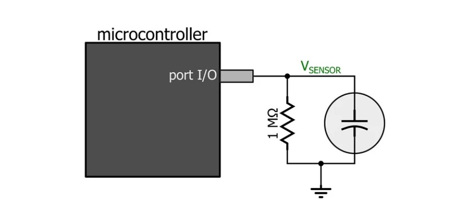 Image source
Making the circuit
After learning and understanding how the sensor works, I determined the number of pins required for the sensor and the LED. Based on this, I selected the ATtiny1624 microcontroller, as it provides sufficient I/O pins and better flexibility for the project.
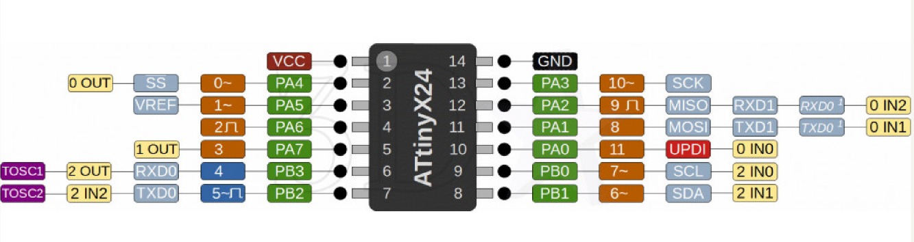
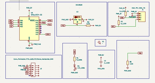
After understanding how the sensor works, I designed the circuit in KiCad. I selected the ATtiny1624 microcontroller because it has enough pins to connect the sensor, LED, and serial communication, making it suitable for this project.
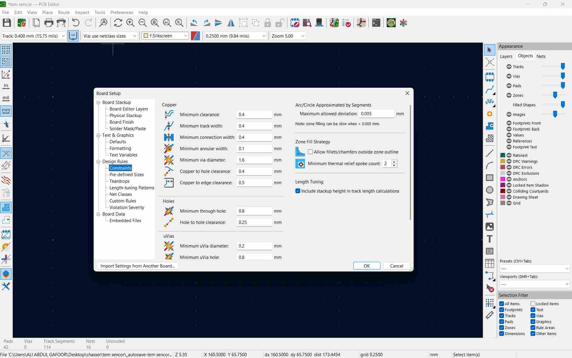
To check the connection use Ruleschecker tool
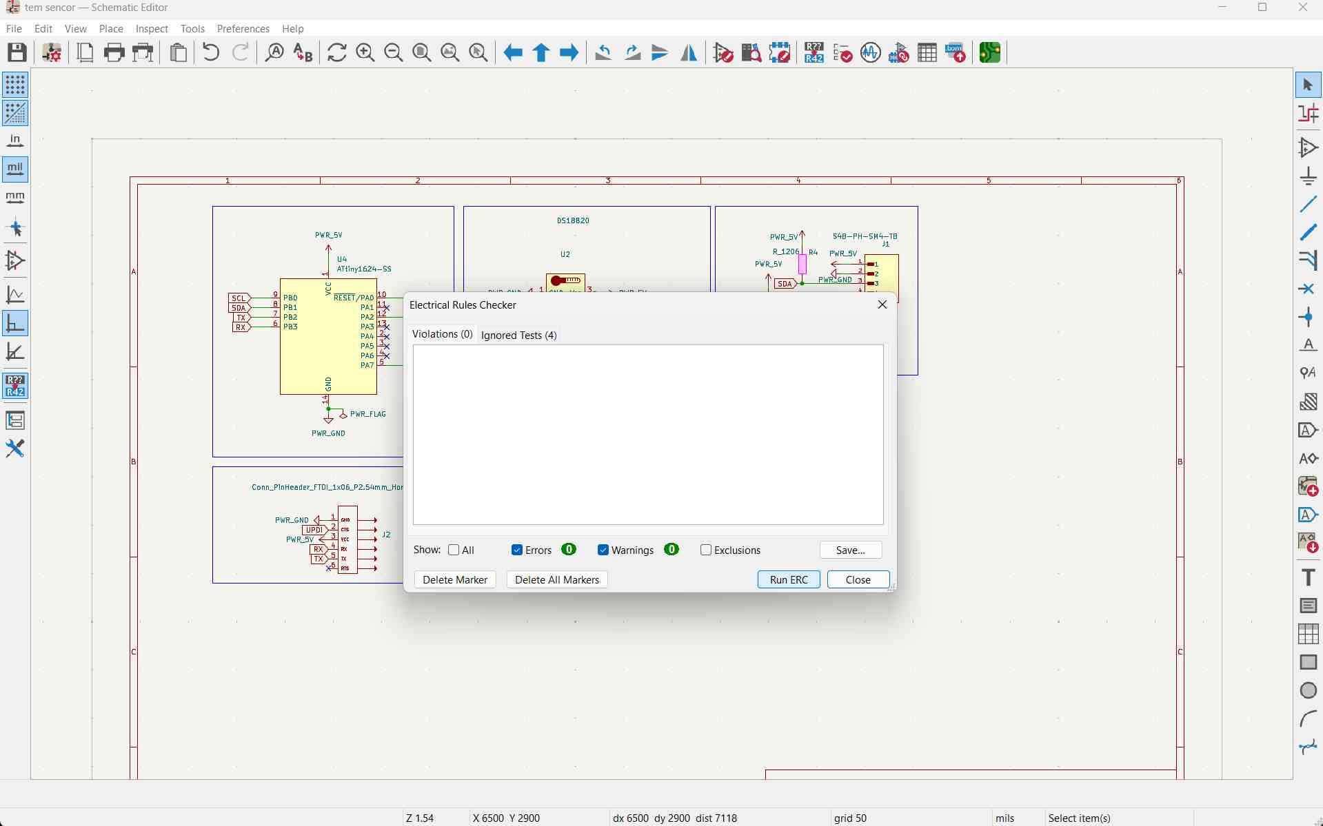
Open the schematic editor. We need to specify the design rules
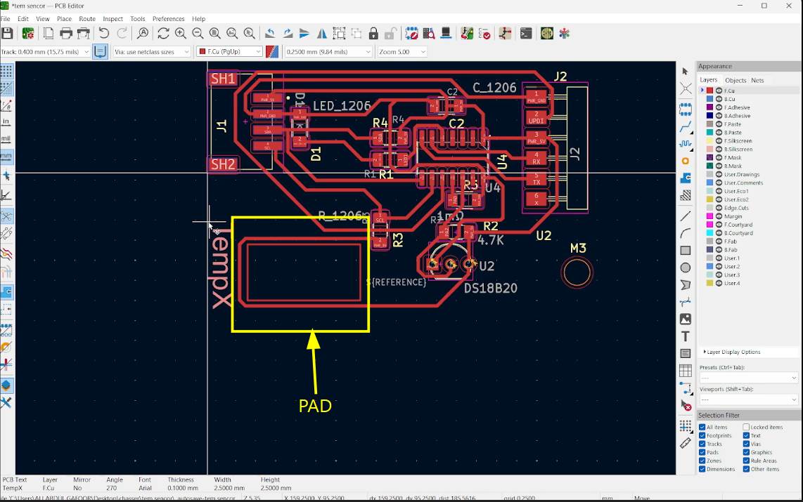
First, draw a rectangle using the square tool in KiCad PCB Editor to make a pad.
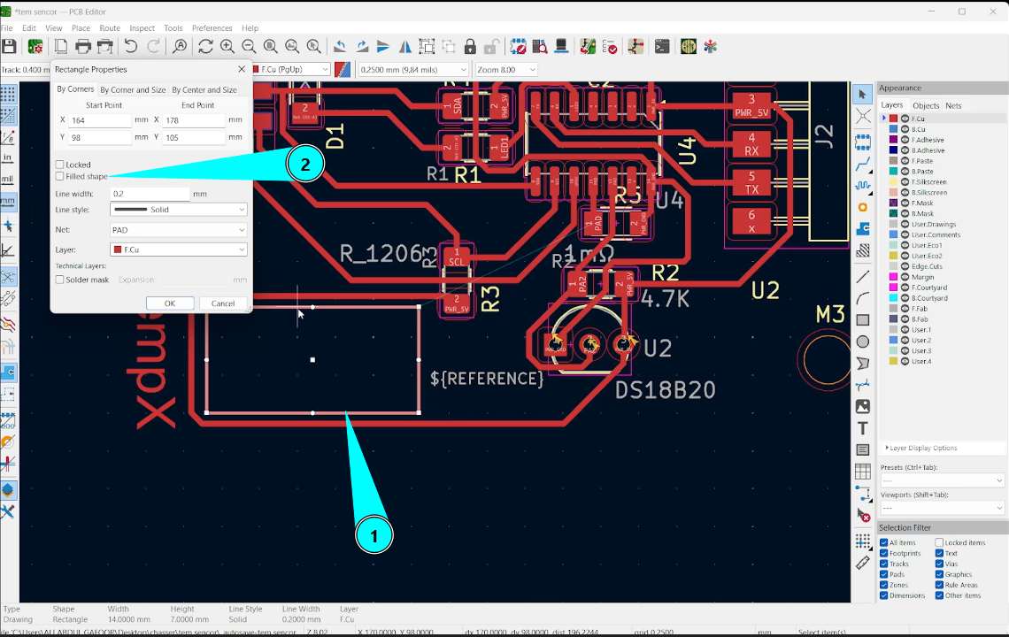
Double-click the rectangle, then select the 'Filled Shape' option
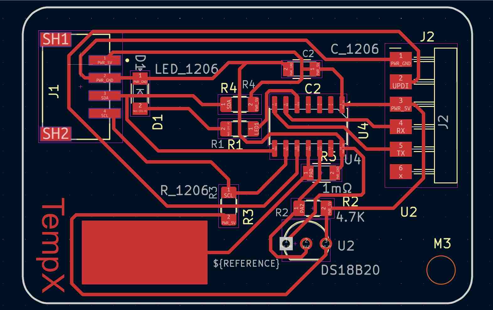
To trace route use the shortcut X or use the route tracks tool in the right panel. Click on edgecuts and using rectangle in tools option draw the outline. Rightclick on the outline and use shape modification option for reshaping outline. You can add text using text tool.
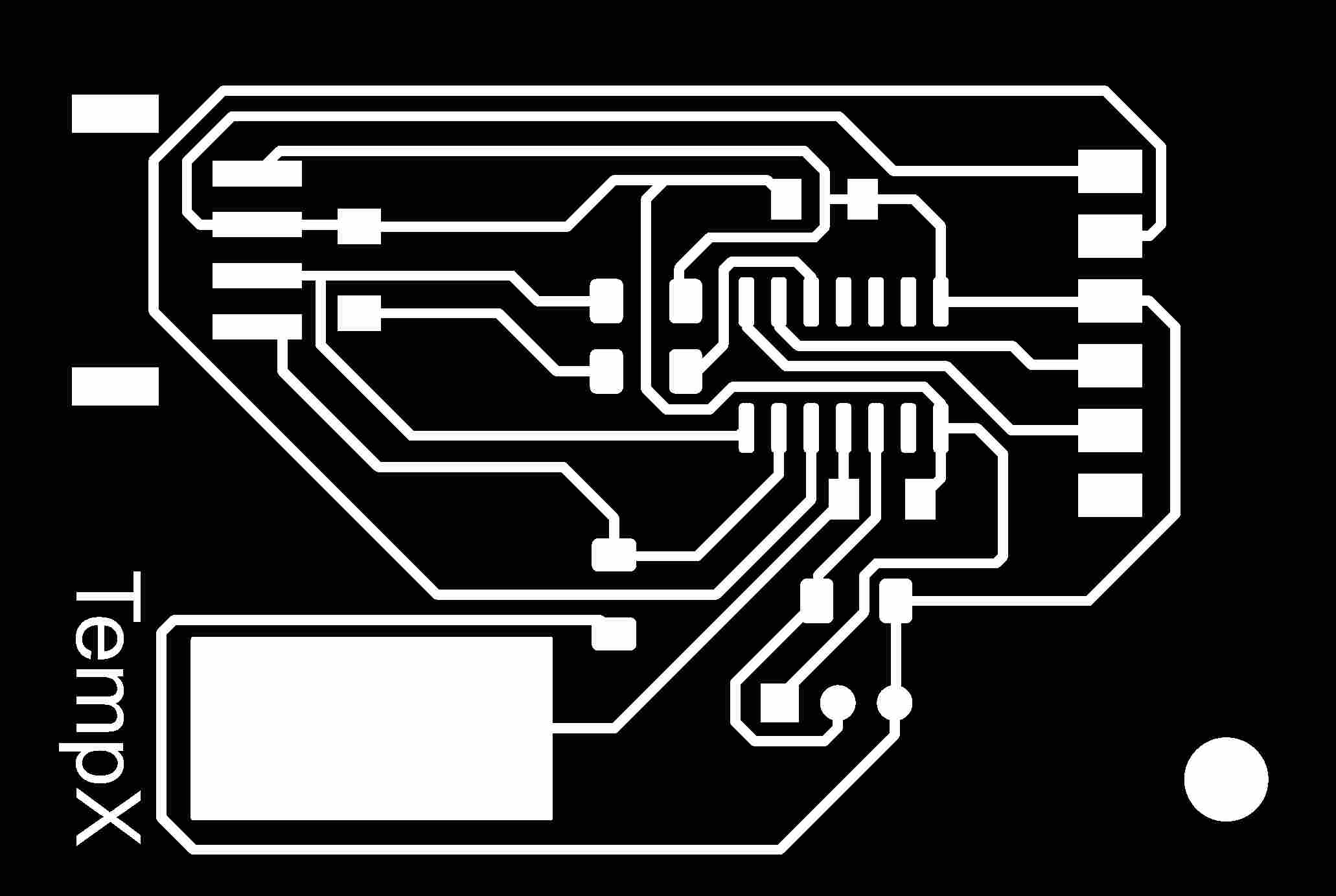
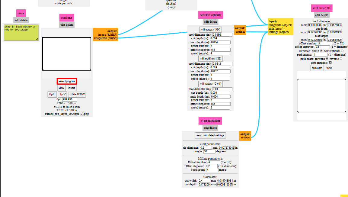
Check the traces using rules checker tool. from file -> Fabrication outputs -> gerbers , we get the gerber format. the gerber files are uploaded in gerber2PNG software to convert it to png format.
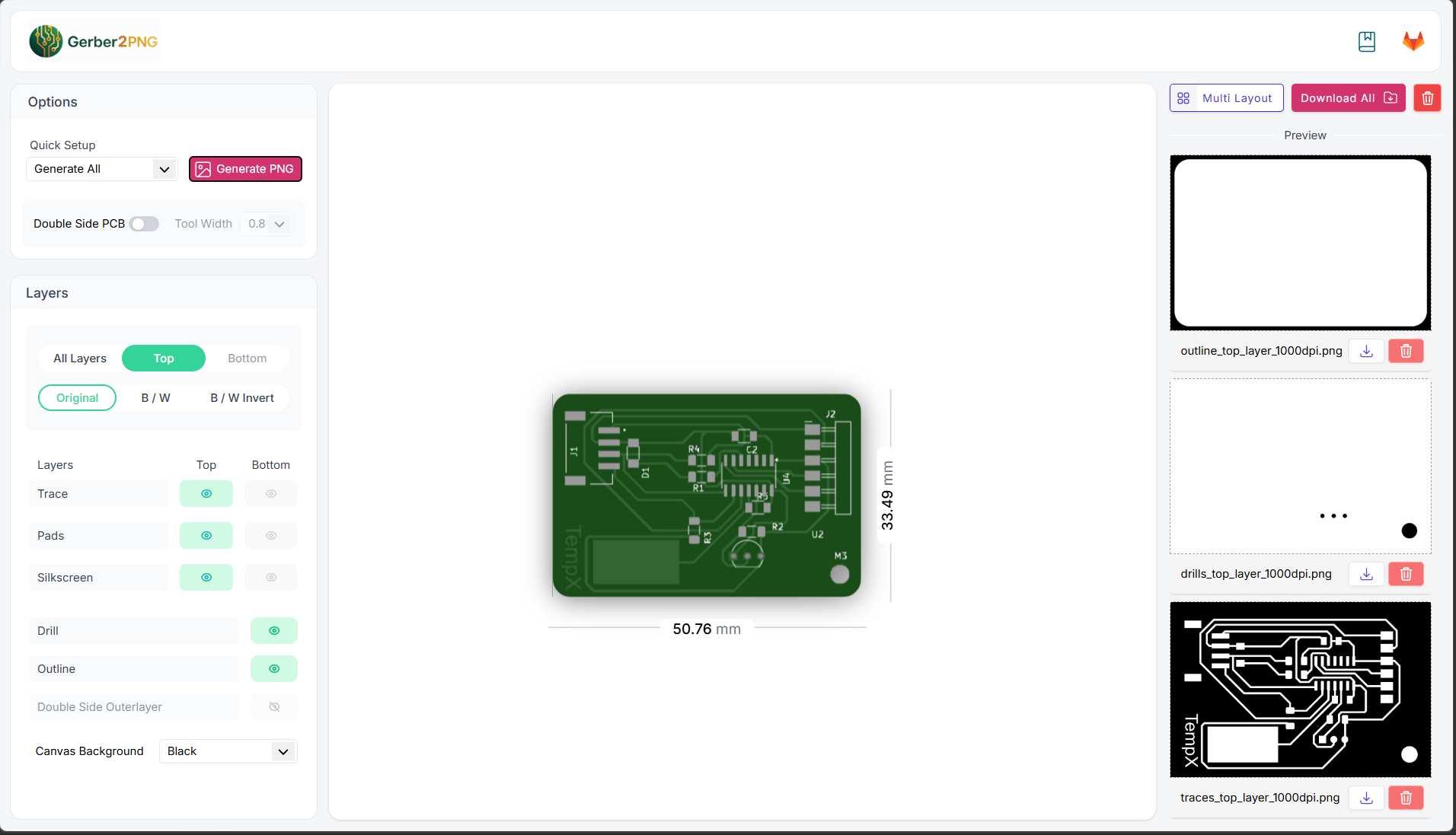
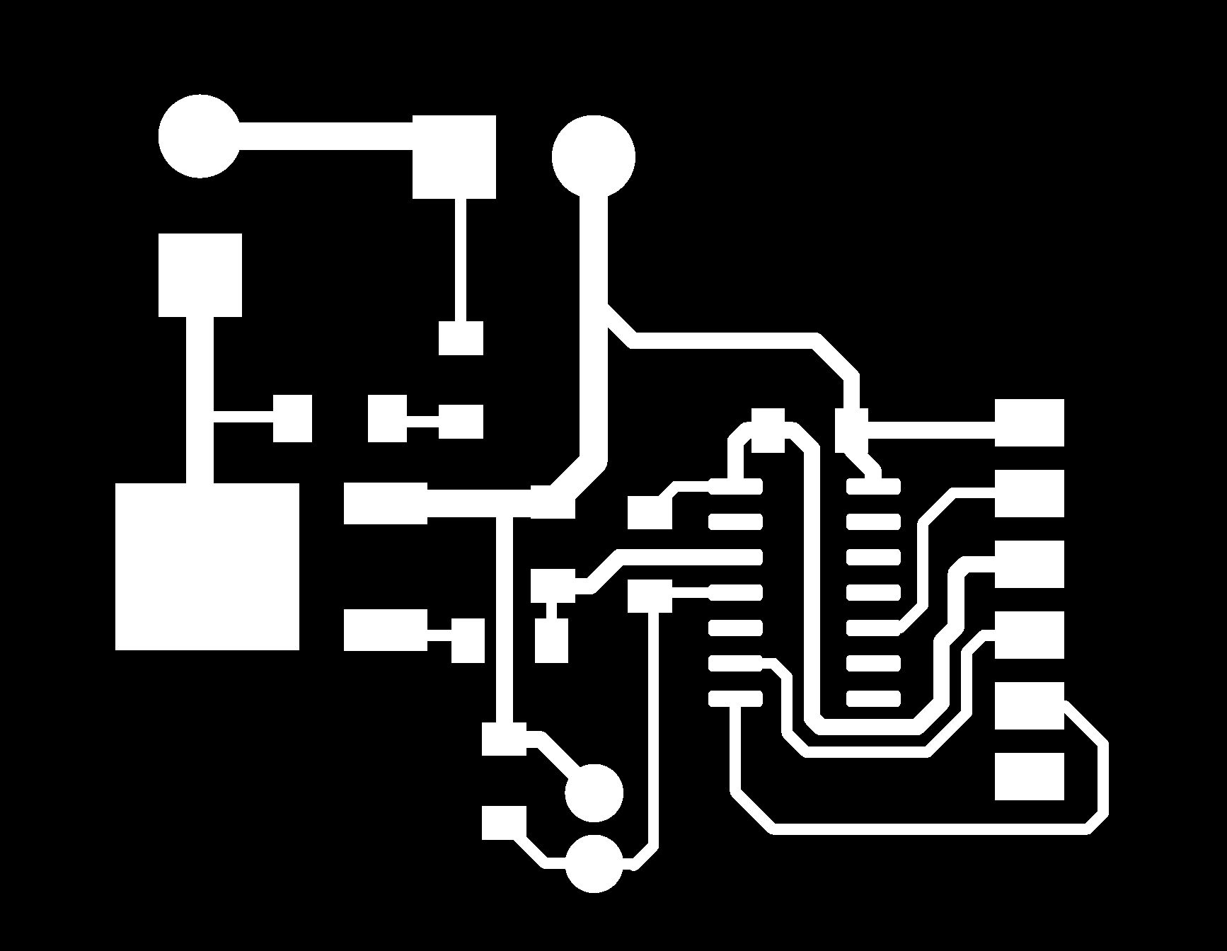
This PNG contains only the PCB traces (copper paths).
This PNG shows all drill holes.

This PNG contains the PCB board outline.

Milling the PCB
Engraving the trace
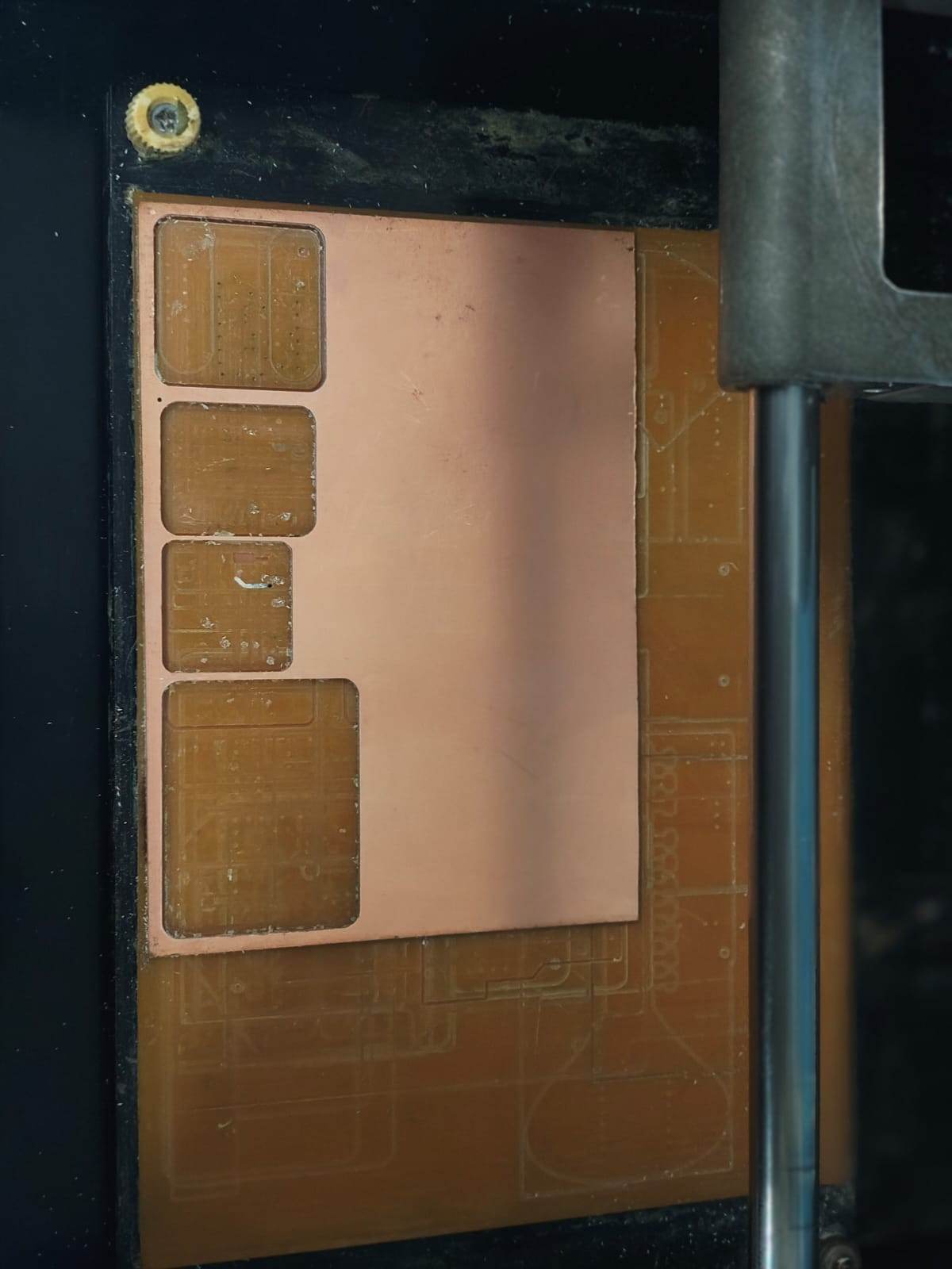
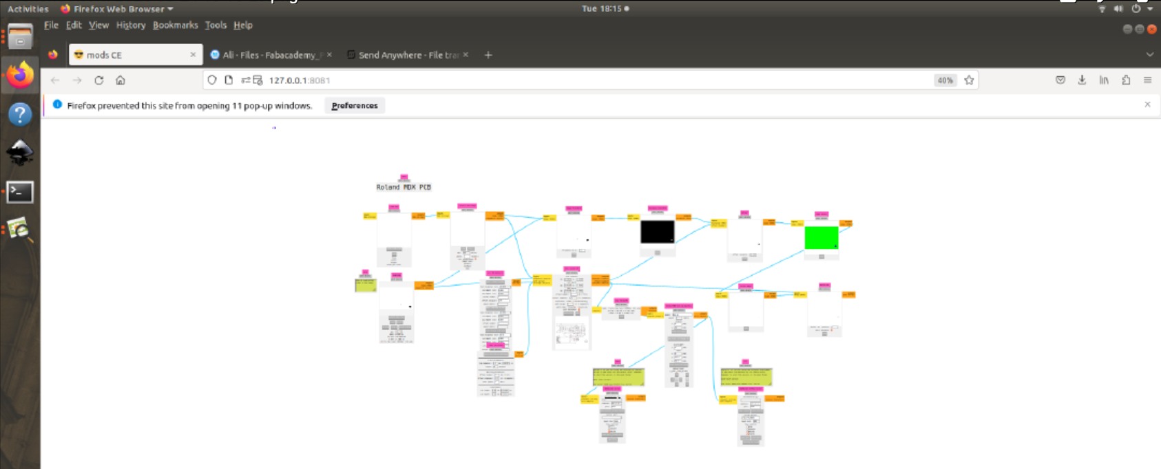
Open Mods CE. Upload the trace layer. I used 0.2mm 60 deg V bit. Millling was done in Modela MDX-20 3D Milling Machine. I set origin as x:6 and y:4. Set the zero position (X, Y, and Z-axis) manually. Adjust milling parameters like spindle speed, feed rate, and depth of cut based on the material and tool specifications.
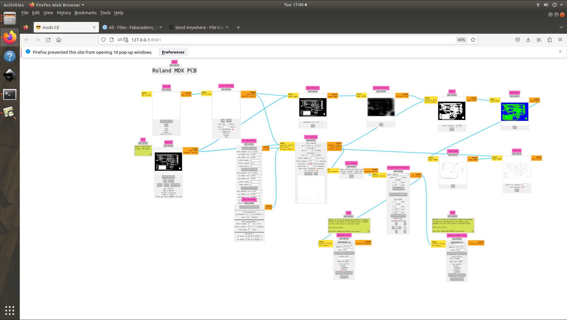
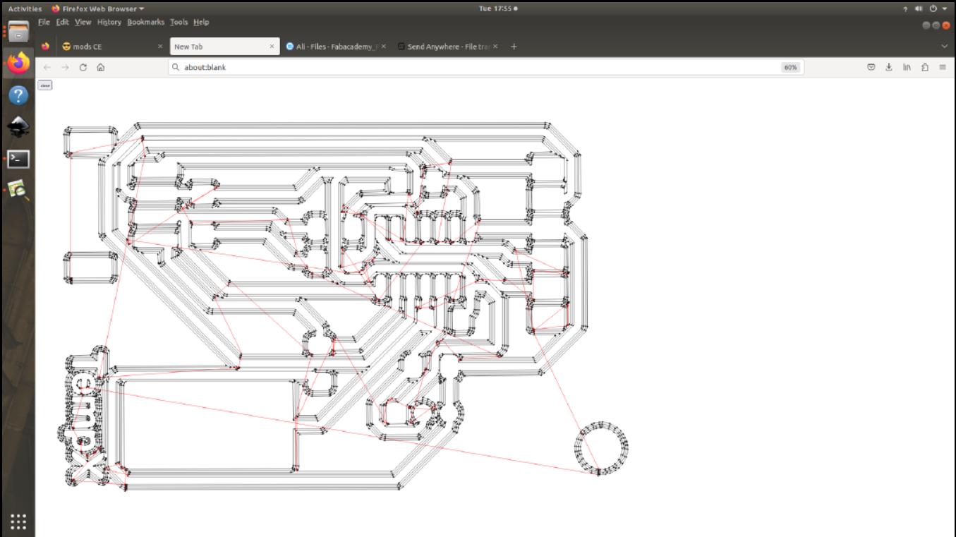
we can view the trace toolpath
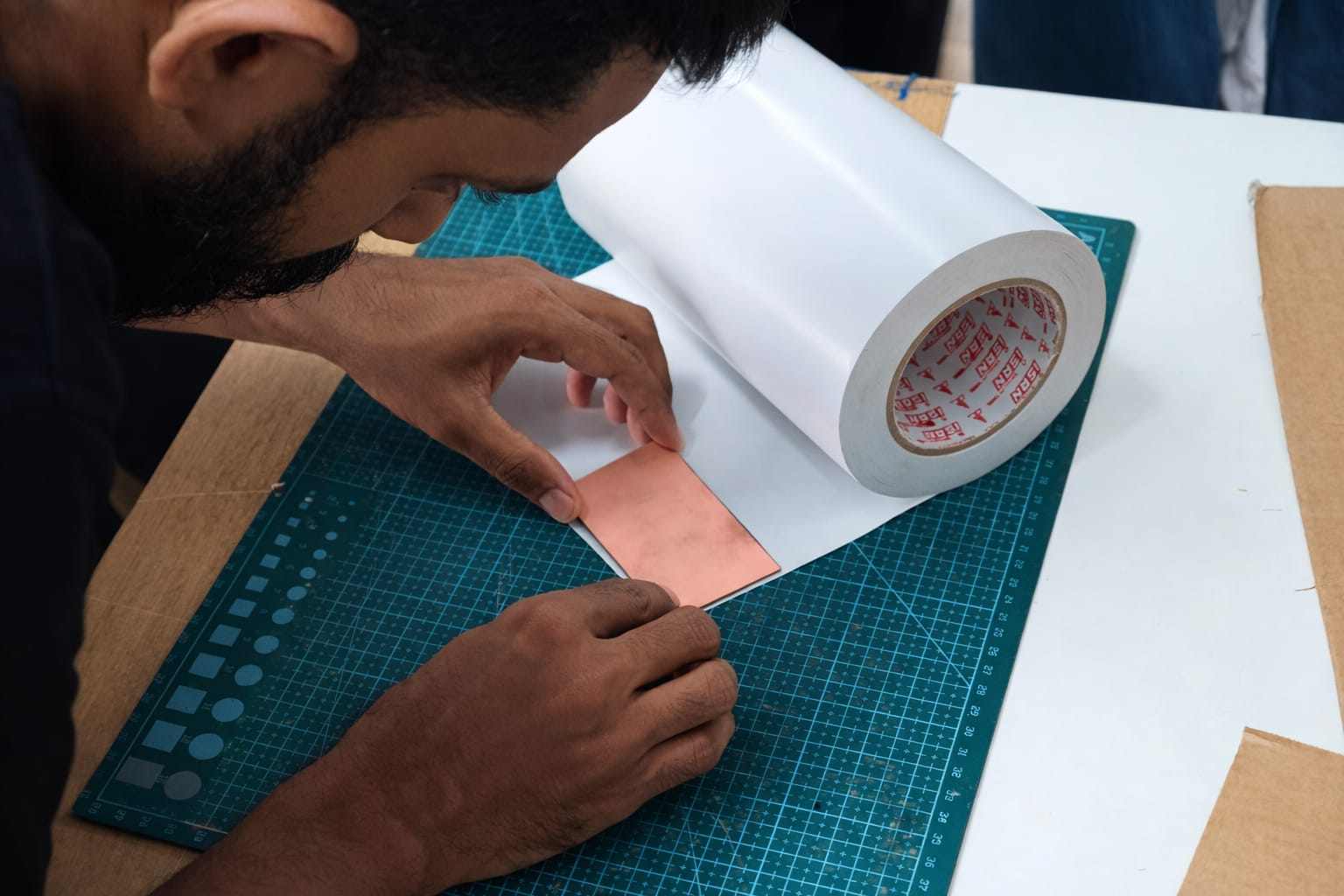
We only have a large PCB available, so we used the remaining space. The other side can be milled by others. This image is for reference on how to apply double-sided Nippo tape for fixing
Click send file option in mods to start engraving the trace
Cutting Outline
After engraving the trace, we have to cut the outline. The outline layer is uploaded in mods CE. We use 1/32" bit.
The toolpath is shown below.
Using send file option initiate the cutting process.
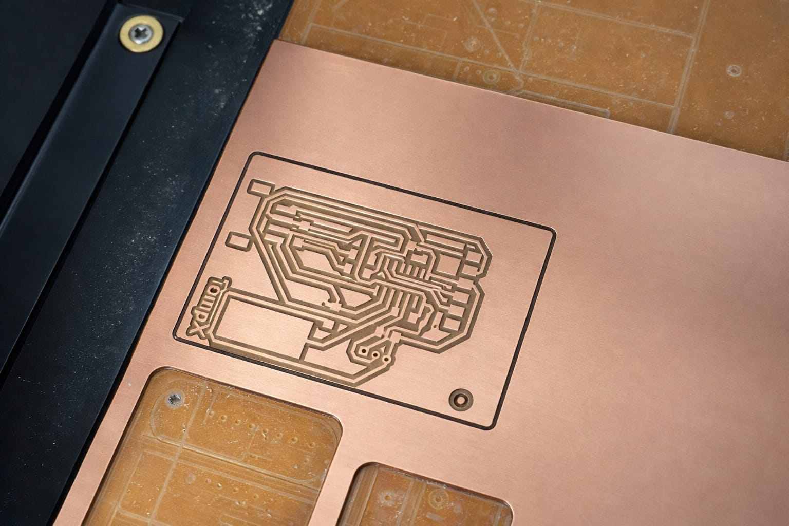
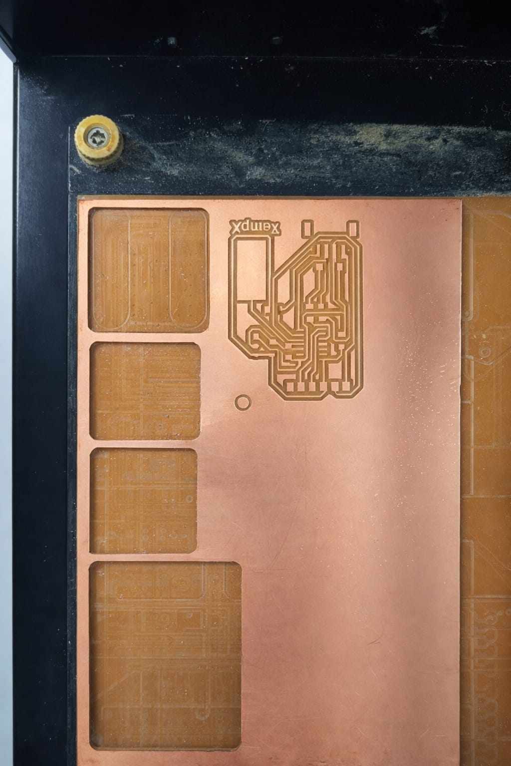
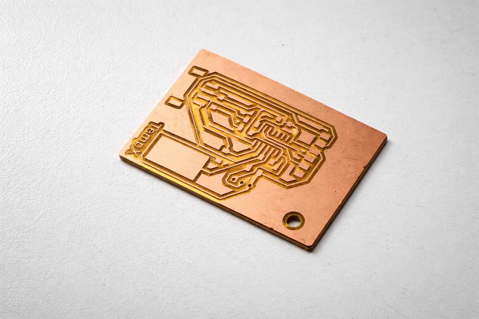
Use a vaccumcleaner to remove dust and debris. Use a scraper to lift the board. And here is the final result.
Assembling the PCB
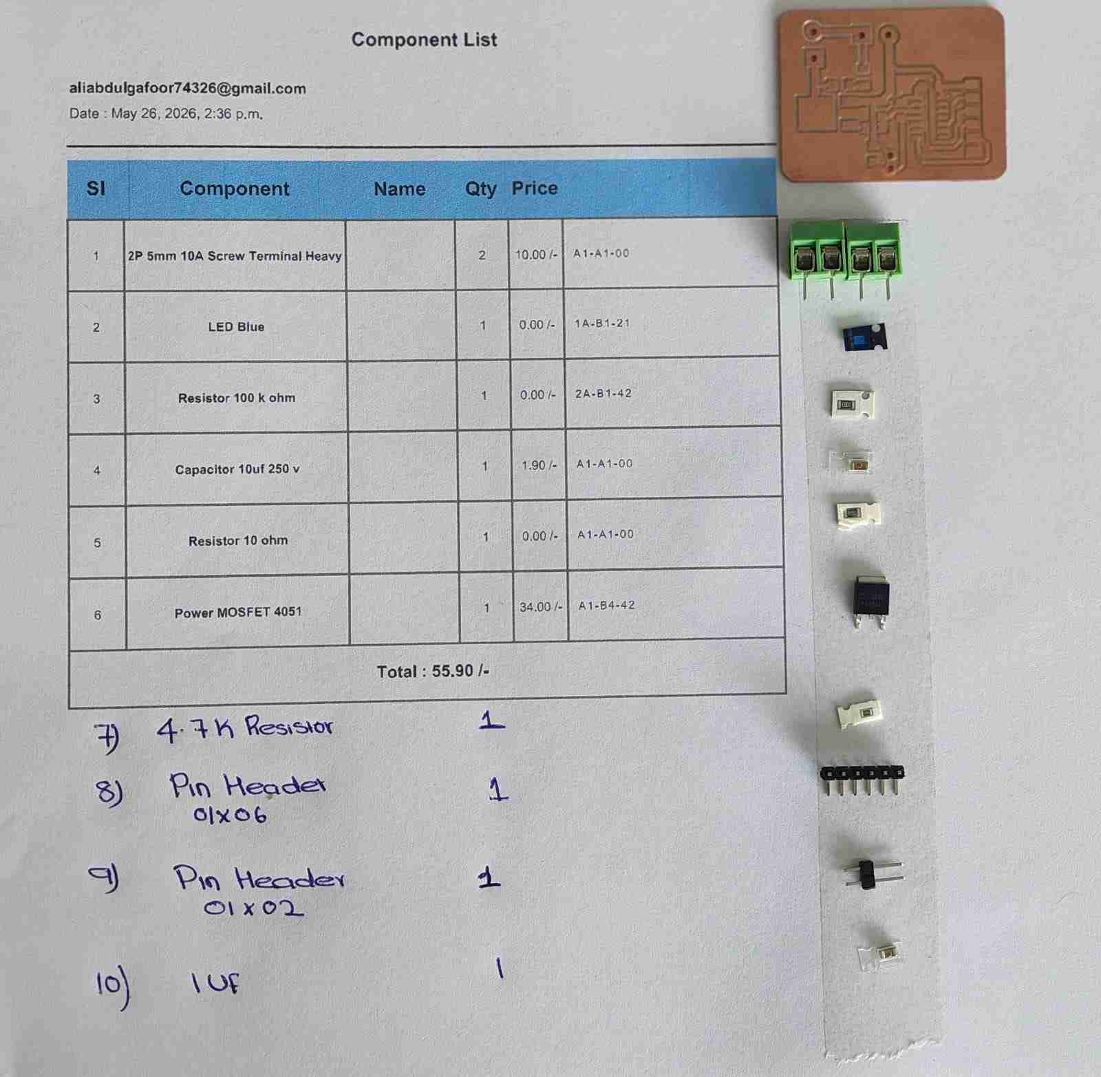
Interactive HTML BOM is generated in KiCad and the components were taken from inventory.
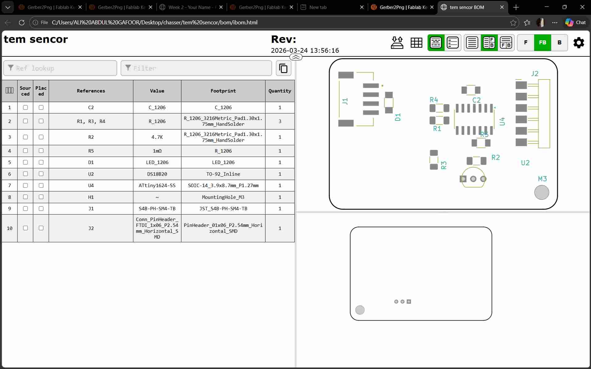
This is the list of components created by FabTash.
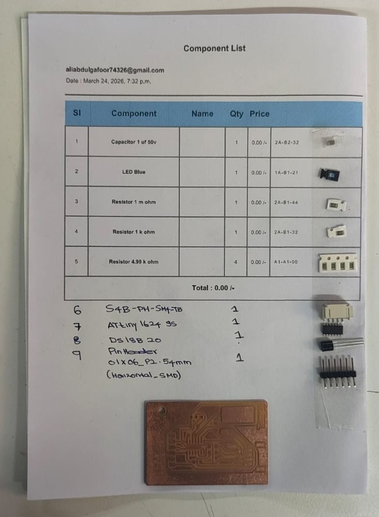
The components are soldered into the PCB
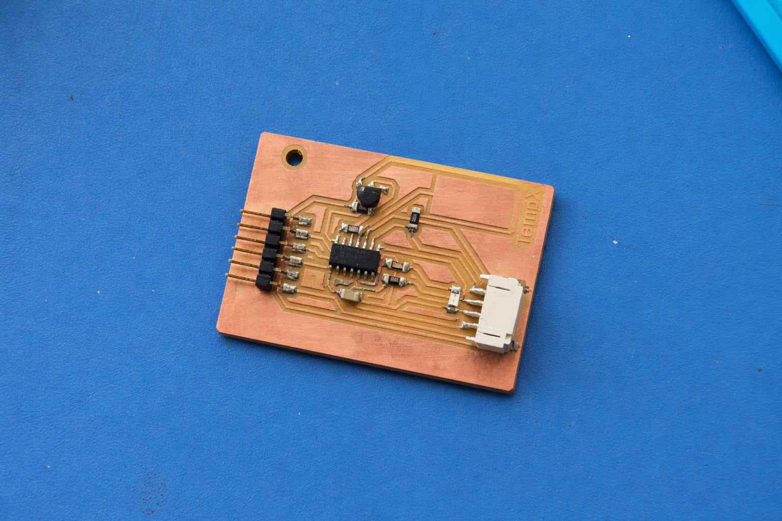
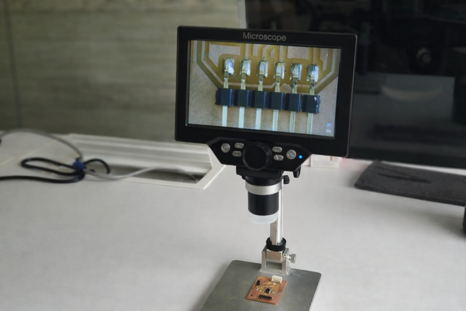
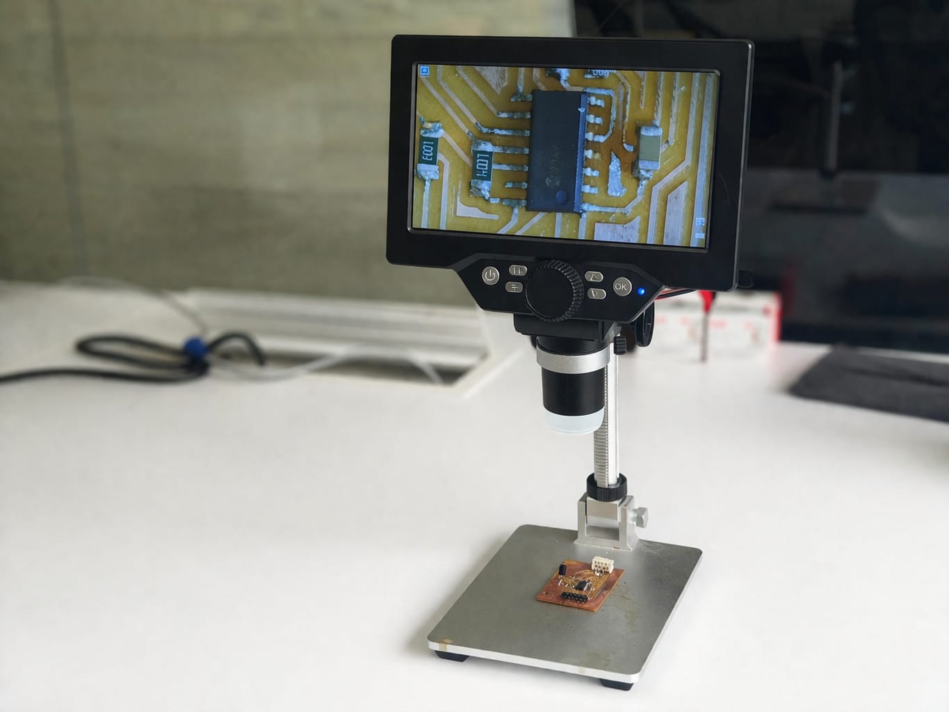
I used a digital microscope to check that all components are soldered properly and there are no shorts.
Programming
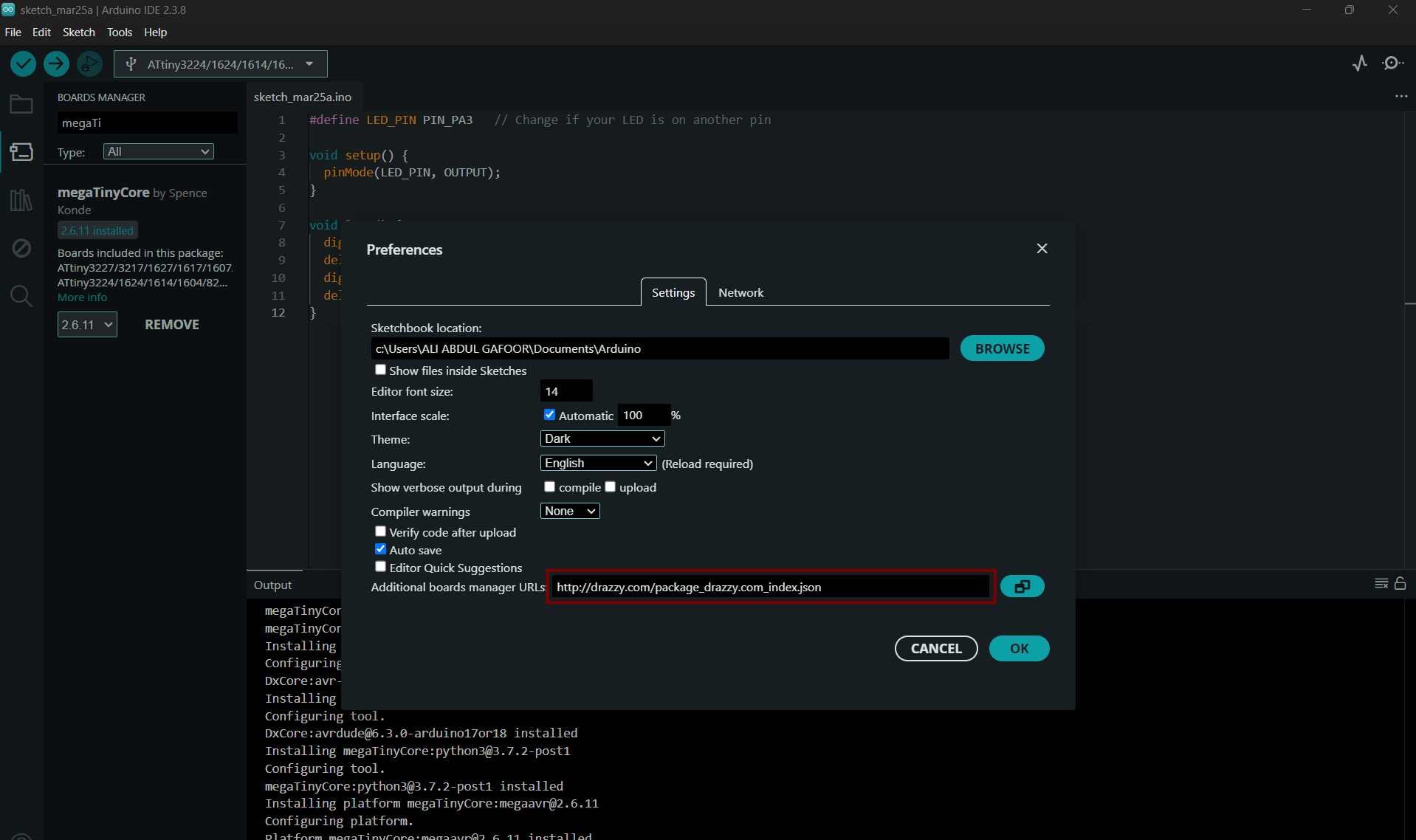
I connected my PCB to a programmer to connect it to my laptop and ran a simple blink test to check if its working. I referred to Revishanker's documentation to setup the board in arduino IDE.
Open Arduino IDE → Preferences and add the MegaTinyCore URL: http://drazzy.com/package_drazzy.com_index.json
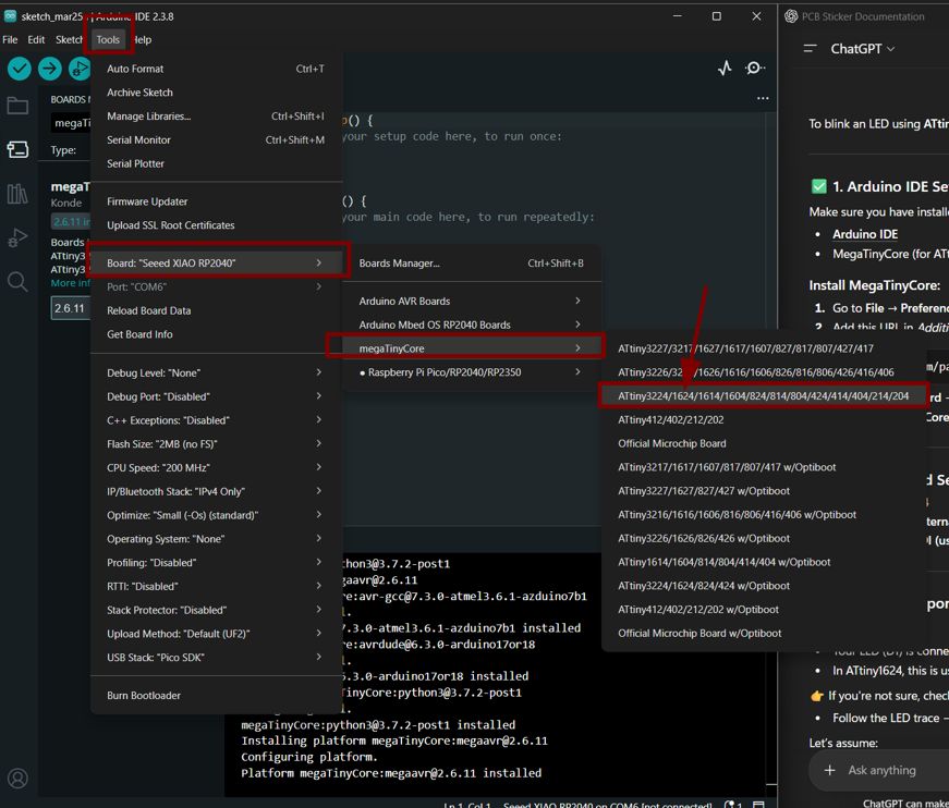
Then go to Boards Manager, search for MegaTinyCore, and install it.
Go to Tools → Board → megaTinyCore, select ATtiny3224/1624 series, and choose ATtiny1624.
What I Tried
- Connected a temperature sensor to the ATtiny board
- Wrote code to read temperature values
- Tested LED output for verification
Result
- LED is working correctly ✓
- Temperature sensor is NOT giving any output ✗
Problem Analysis
Since the LED is functioning properly, the microcontroller and basic circuit are working. The issue is specifically related to the temperature sensor or its configuration.
Possible Causes:
- Incorrect wiring of the sensor
- Wrong pin configuration in code
- Missing pull-up resistor (for digital sensors like DS18B20)
- Using wrong type of pin (analog vs digital)
- Sensor may be damaged
- Library or code issue
Corrections Made
- Rechecked all wiring connections (VCC, GND, DATA)
- Verified correct pin mapping in the code
- Ensured proper resistor usage (4.7kΩ pull-up for DS18B20)
- Tested sensor separately with minimal code
- Confirmed correct sensor type and matching library
- Checked power supply (3.3V / 5V compatibility)
Testing Method
Used a simple serial test program to verify sensor output:
    // Example test logic

    Read temperature value

    If value == error → print "Sensor Error"

    Else → print temperature
Conclusion
The LED working confirms that the ATtiny microcontroller is functioning correctly. The temperature sensor issue is likely due to wiring, configuration, or sensor fault. Further testing with correct wiring and verified components is required.
Next Steps
- Test with another temperature sensor
- Double-check datasheet and pin configuration
- Use a simpler test setup before integrating with full system
On FInal Project time WIth Help of saheen I tried on a new pcb
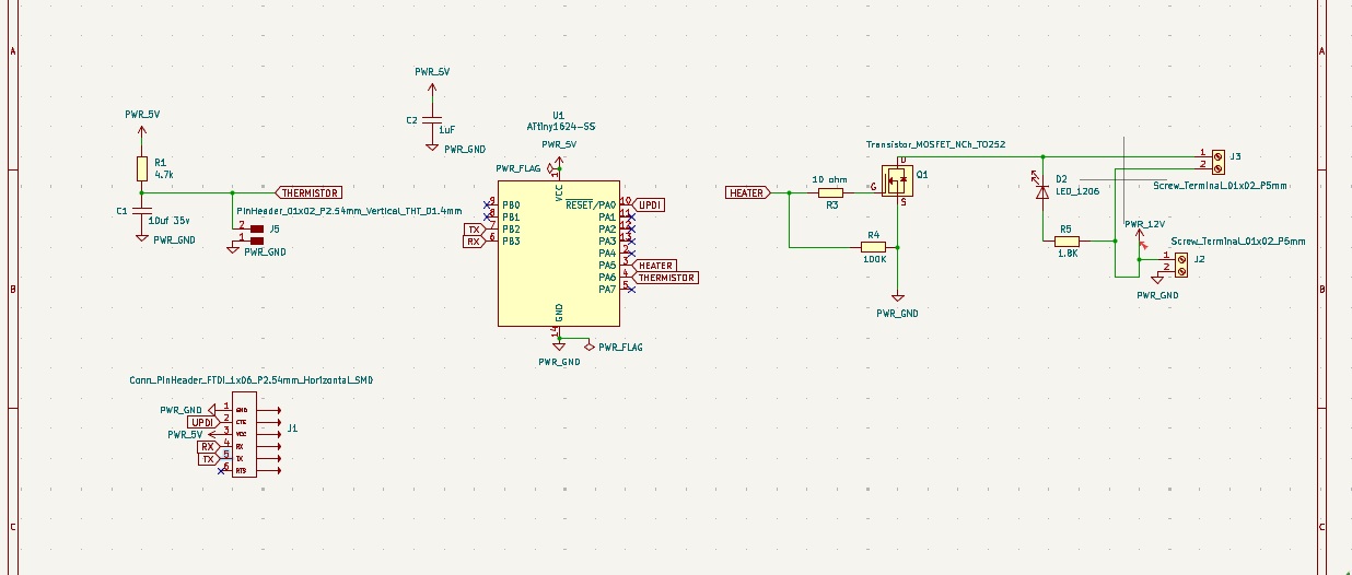
This time, I integrated both input and output devices together, and Shaheen suggested using a 100k thermistor instead of the DS18B20.
this is my new skematic i tried at the time of final project so i redesigned it with help of saheen
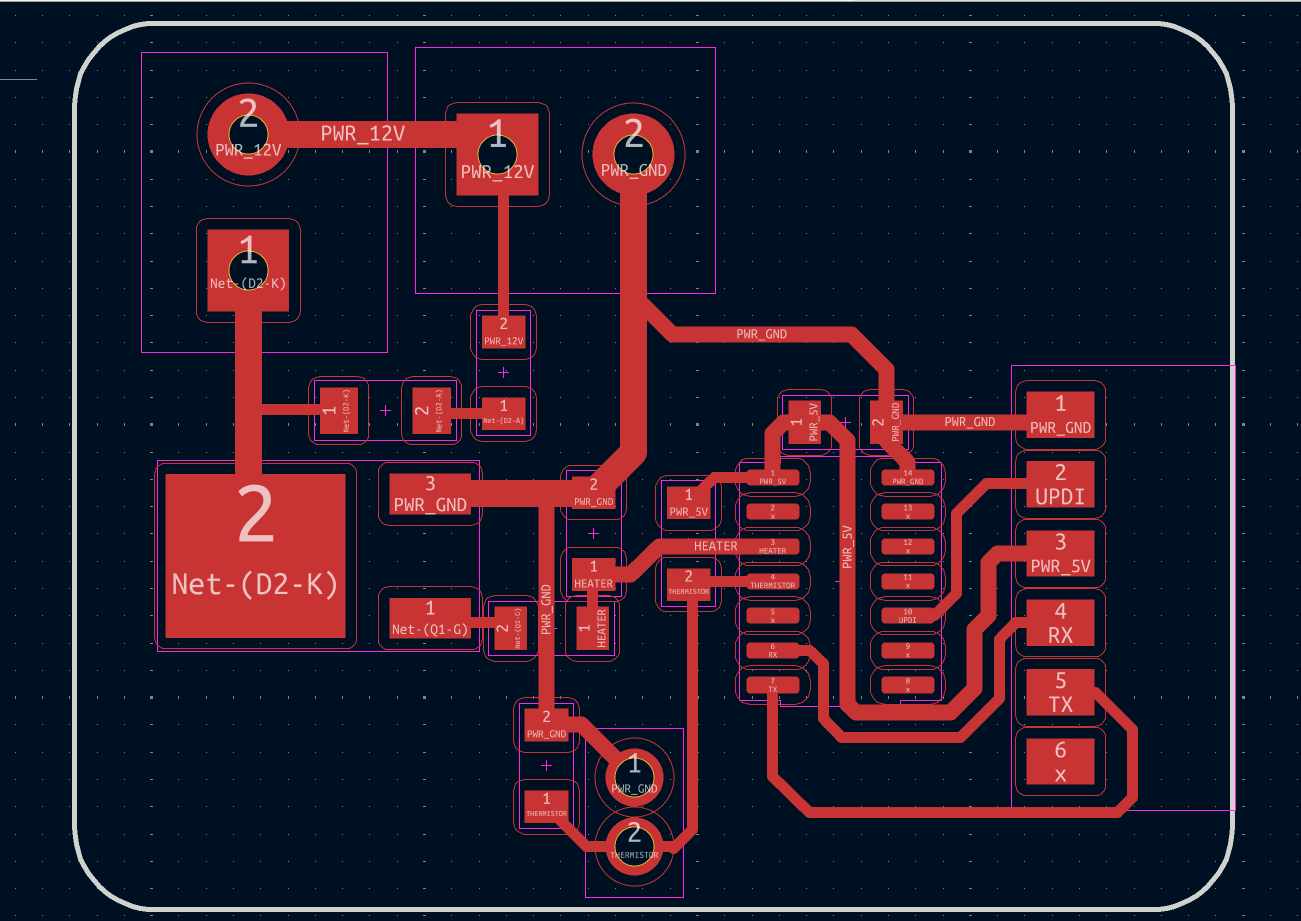
This is my new pcb layout look like
Check the traces using rules checker tool. from file -> Fabrication outputs -> gerbers , we get the gerber format. the gerber files are uploaded in gerber2PNG software to convert it to png format.
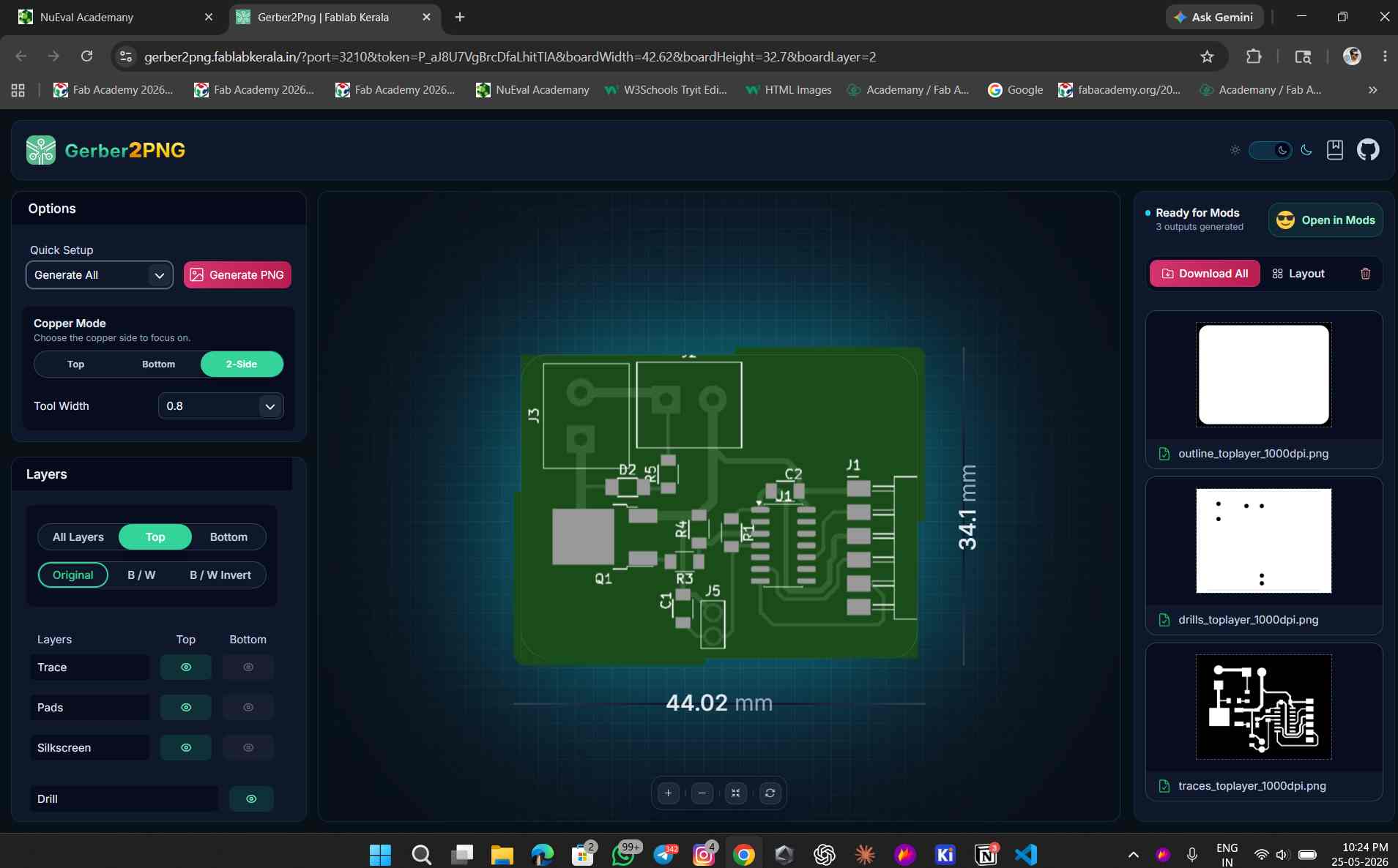
this is the converted gerber files to png format


Rest of the process are same as we done before
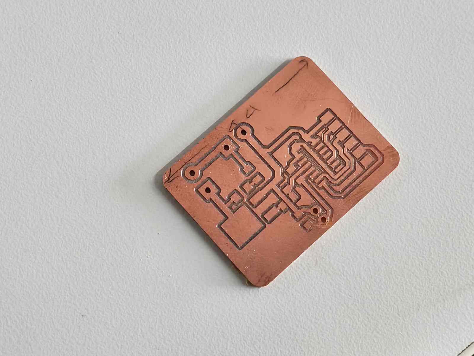
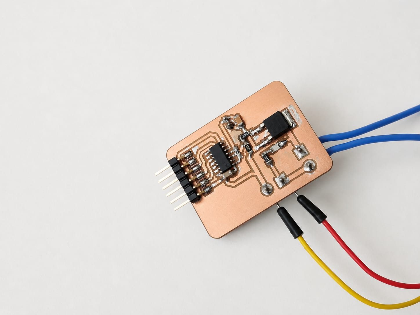
this is my new final pcb after milling
this is components i took for new pcb and attiny 1624 i desolderd from my old pcb
this is the new pcb after soldering
this is the code i used for testing the new pcb
/*
  Thermistor + PTC Heater Controller — ATtiny1624 (megaTinyCore)

  Thermistor: VCC → 4.7kΩ → PA6 → Thermistor → GND
  Heater:     PA5 → N-channel MOSFET gate → PTC heater

  State machine:
    HEATING     → heater full ON until temp ≥ 60 °C
    MAINTAINING → bang-bang ±0.5 °C for 3 minutes
    COOLING     → heater OFF, returns to room temp
*/

#include <math.h>

// ── Pins ──────────────────────────────────────────────────────────────────────
#define THERM_PIN   PIN_PA6
#define HEATER_PIN  PIN_PA5

// ── Circuit constants ─────────────────────────────────────────────────────────
const float VCC     = 5.0;
const float R_FIXED = 4700.0;

// ── Thermistor (Beta equation) ────────────────────────────────────────────────
const float BETA      = 3950.0;
const float T0_KELVIN = 298.15;   // 25 °C in Kelvin
const float R0        = 100000.0; // 100 kΩ at 25 °C

// ── ADC ───────────────────────────────────────────────────────────────────────
const int   NUM_SAMPLES = 16;
const float ADC_MAX     = 1023.0;

// ── Heater setpoint & hysteresis ─────────────────────────────────────────────
const float TARGET_TEMP = 60.0;   // °C
const float HYST_HIGH   = 60.5;   // turn heater OFF above this
const float HYST_LOW    = 59.5;   // turn heater ON below this

// ── Hold duration ─────────────────────────────────────────────────────────────
const unsigned long HOLD_MS = 3UL * 60UL * 1000UL; // 3 minutes

// ── State machine ─────────────────────────────────────────────────────────────
enum HeaterState { HEATING, MAINTAINING, COOLING };
HeaterState state = HEATING;
unsigned long holdStart = 0;

// ─────────────────────────────────────────────────────────────────────────────
void setup() {
  Serial.begin(115200);

  pinMode(HEATER_PIN, OUTPUT);
  digitalWrite(HEATER_PIN, LOW);  // safe start — heater off

  analogReference(VDD);
  analogReadResolution(10);

  delay(2000);
  Serial.println("Heater Controller — ATtiny1624");
  Serial.println("Target: 60 C  |  Hold: 3 minutes");
  Serial.println("------------------------------------");

  // Begin heating immediately
  digitalWrite(HEATER_PIN, HIGH);
  Serial.println("[STATE] HEATING");
}

// ── ADC helpers ───────────────────────────────────────────────────────────────
float readVoltage() {
  long sum = 0;
  for (int i = 0; i < NUM_SAMPLES; i++) {
    sum += analogRead(THERM_PIN);
    delay(2);
  }
  return (sum / (float)NUM_SAMPLES / ADC_MAX) * VCC;
}

float voltageToResistance(float v) {
  if (v <= 0.0 || v >= VCC) return -1.0;   // open / short fault
  return R_FIXED * v / (VCC - v);
}

float resistanceToCelsius(float r) {
  if (r <= 0) return NAN;
  float invT = (1.0 / T0_KELVIN) + (1.0 / BETA) * log(r / R0);
  return (1.0 / invT) - 273.15;
}

// ─────────────────────────────────────────────────────────────────────────────
void loop() {
  float voltage    = readVoltage();
  float resistance = voltageToResistance(voltage);
  float tempC      = resistanceToCelsius(resistance);

  if (isnan(tempC) || resistance < 0) {
    digitalWrite(HEATER_PIN, LOW);
    Serial.println("ERROR: Sensor fault — heater OFF for safety");
    delay(1000);
    return;
  }

  switch (state) {

    case HEATING:
      digitalWrite(HEATER_PIN, HIGH);
      if (tempC >= TARGET_TEMP) {
        holdStart = millis();
        state = MAINTAINING;
        Serial.println("[STATE] MAINTAINING");
      }
      break;

    case MAINTAINING: {
      if (tempC >= HYST_HIGH) {
        digitalWrite(HEATER_PIN, LOW);
      } else if (tempC <= HYST_LOW) {
        digitalWrite(HEATER_PIN, HIGH);
      }
      if (millis() - holdStart >= HOLD_MS) {
        digitalWrite(HEATER_PIN, LOW);
        state = COOLING;
        Serial.println("[STATE] COOLING — heater OFF");
      }
      break;
    }

    case COOLING:
      digitalWrite(HEATER_PIN, LOW);
      break;
  }

  Serial.print("Temp: ");
  Serial.print(tempC, 1);
  Serial.print(" C  |  R: ");
  Serial.print(resistance / 1000.0, 2);
  Serial.print(" kOhm  |  V: ");
  Serial.print(voltage, 3);
  Serial.print(" V  |  Heater: ");
  Serial.print(digitalRead(HEATER_PIN) ? "ON " : "OFF");
  Serial.print("  |  State: ");

  switch (state) {
    case HEATING:     Serial.print("HEATING    "); break;
    case MAINTAINING: {
      unsigned long secs = (HOLD_MS - (millis() - holdStart)) / 1000;
      Serial.print("MAINTAIN  ");
      Serial.print(secs / 60);
      Serial.print("m ");
      Serial.print(secs % 60);
      Serial.print("s left");
      break;
    }
    case COOLING:     Serial.print("COOLING    "); break;
  }
  Serial.println();

  delay(1000);
}
this code is made with claude ai the here below i give proment i used to genarate this code
ihave been designed and milled a pcb.this pcb consist of 1 themistor and 1 ptc 12heater .and iam usinf attiny 1624 ic for this pcb.i connected thermister in PA6 using this code/*
  Thermistor Reader — ATtiny1624 (megaTinyCore)
  Circuit: VCC → 4.7kΩ → PA7 (AIN7) → Thermistor → GND
  ⚠ USART0 remapped via Serial.swap(1):
      TX → PA1  (connect to USB-Serial adapter)
      RX → PA2  (unused)
  This frees PA7 from its default USART0-RX role.
*/
#include <math.h>
#define THERM_PIN   PIN_PA6
const float VCC       = 5;
const float R_FIXED   = 4700.0;
const float BETA      = 3950.0;
const float T0_KELVIN = 298.15;
const float R0        = 100000.0;
const int   NUM_SAMPLES = 16;
const float ADC_MAX   = 1023.0;
void setup() {
  Serial.begin(115200);
  analogReference(VDD);
  analogReadResolution(10);
  delay(2000);
  Serial.println("Thermistor Reader - ATtiny1624");
  Serial.println("--------------------------------");
}
float readVoltage() {
  long sum = 0;
  for (int i = 0; i < NUM_SAMPLES; i++) {
    sum += analogRead(THERM_PIN);
    delay(2);
  }
  float raw = sum / (float)NUM_SAMPLES;
  return (raw / ADC_MAX) * VCC;
}
float voltageToResistance(float v) {
  if (v <= 0.0 || v >= VCC) return -1;
  return R_FIXED * v / (VCC - v);
}
float resistanceToCelsius(float r) {
  if (r <= 0) return NAN;
  float invT = (1.0 / T0_KELVIN) + (1.0 / BETA) * log(r / R0);
  return (1.0 / invT) - 273.15;
}
void loop() {
  float voltage    = readVoltage();
  float resistance = voltageToResistance(voltage);
  float tempC      = resistanceToCelsius(resistance);
  float tempF      = tempC * 9.0 / 5.0 + 32.0;
  if (isnan(tempC) || resistance < 0) {
    Serial.println("ERROR: Sensor fault - check wiring");
  } else {
    Serial.print("Temp: ");
    Serial.print(tempC, 1);
    Serial.print(" C  /  ");
    Serial.print(tempF, 1);
    Serial.print(" F    |  R_th: ");
    Serial.print(resistance / 1000.0, 2);
    Serial.print(" kOhm    |  V_adc: ");
    Serial.print(voltage, 3);
    Serial.println(" V");
  }
  delay(1000);
}.this code workes perfectley no error .so next ineed to connect heater to PA5 pin along with nchannel mosphet.ineed to make heater with 60degree cel.heater need to be turn up to 60 degreen and continue in 60degree and after 3 miniute turn off back to room temparature
while testising i tapped both heater and thermister with heat resisting tape
conclusion
at last ido the input and output devices working together. the heater is able to reach 60 degree and maintain it for 3 minute and then turn off. the code is generated with the help of claude ai and i have given the proment to generate this code above. i have also used chatgpt for debugging and technical guidance.References
- ChatGPT (OpenAI) – Used for code generation, debugging, and technical guidance.
- Claude AI (Anthropic) – Used for code generation and troubleshooting assistance.
- Fab Academy Documentation – Used as a reference for electronics design, embedded programming, and project documentation.
file
- Download ZIP File - Gerber files
- Download KiCad Files - Kicad Files