week 07.COMPUTER CONTROLLED MACHINING
This week focuses on computer-controlled machining, where digital designs are translated into physical objects using CNC machines. The objective is to understand how large-scale components can be designed, machined, and assembled accurately using subtractive manufacturing processes.
Our Instructors for this week were Mufeed and Revisankar, along with Saheen for overall guidance.
Objectives
To know more, visitGroup Assignment.
Individual Assignment
The individual assignment is to design, mill, and assemble a large object, approximately meter-scale, using the CNC machine. The goal is to explore how large components are fabricated from sheet materials and assembled into stable structures. Additional challenges are available for extra credit:
Designing a Acrylic Bending Table in Fusion
To fabricate an object using the ShopBot CNC milling machine, I decided to design a parametric modular stackable storage unit in Fusion 360. The process began with sketching the concept and identifying approximate dimensions for the Acrylic Bending Table. After finalizing the idea, I started modeling the design in Fusion by creating the side profile sketch of the unit.
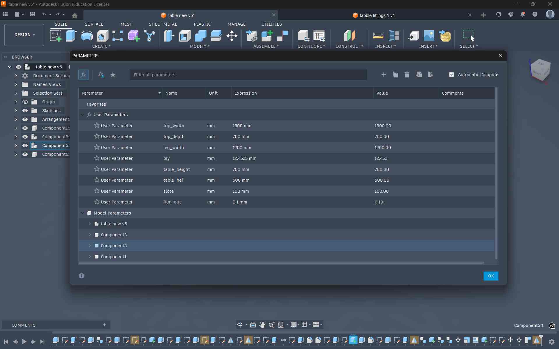
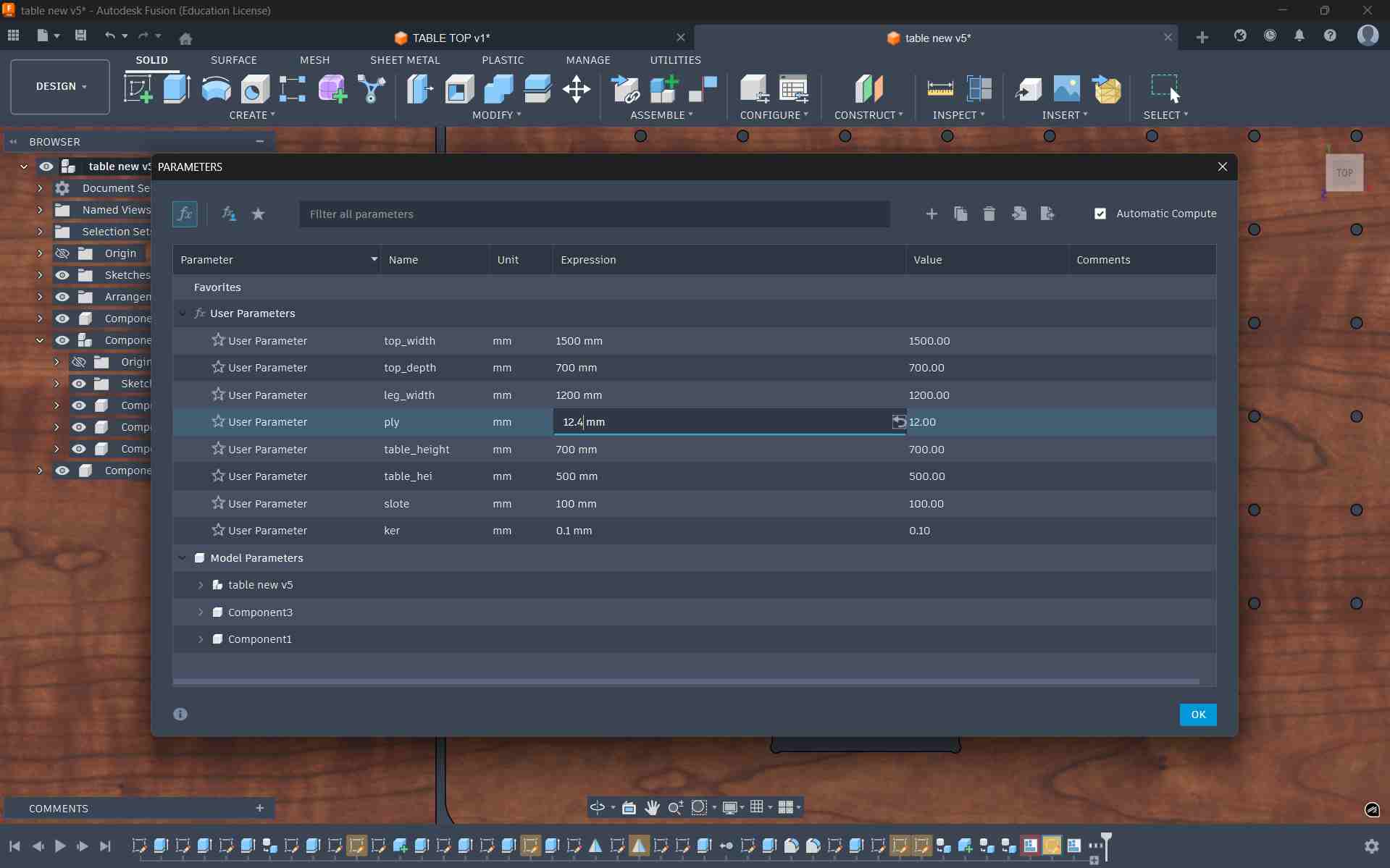
To maintain flexibility in the design, I defined parametric values using Modify → Change Parameters in Fusion. These parameters controlled key dimensions such as thickness, widths, and offsets. Using parameters ensured that any design changes could later be made easily by updating the values rather than editing multiple sketches manually.
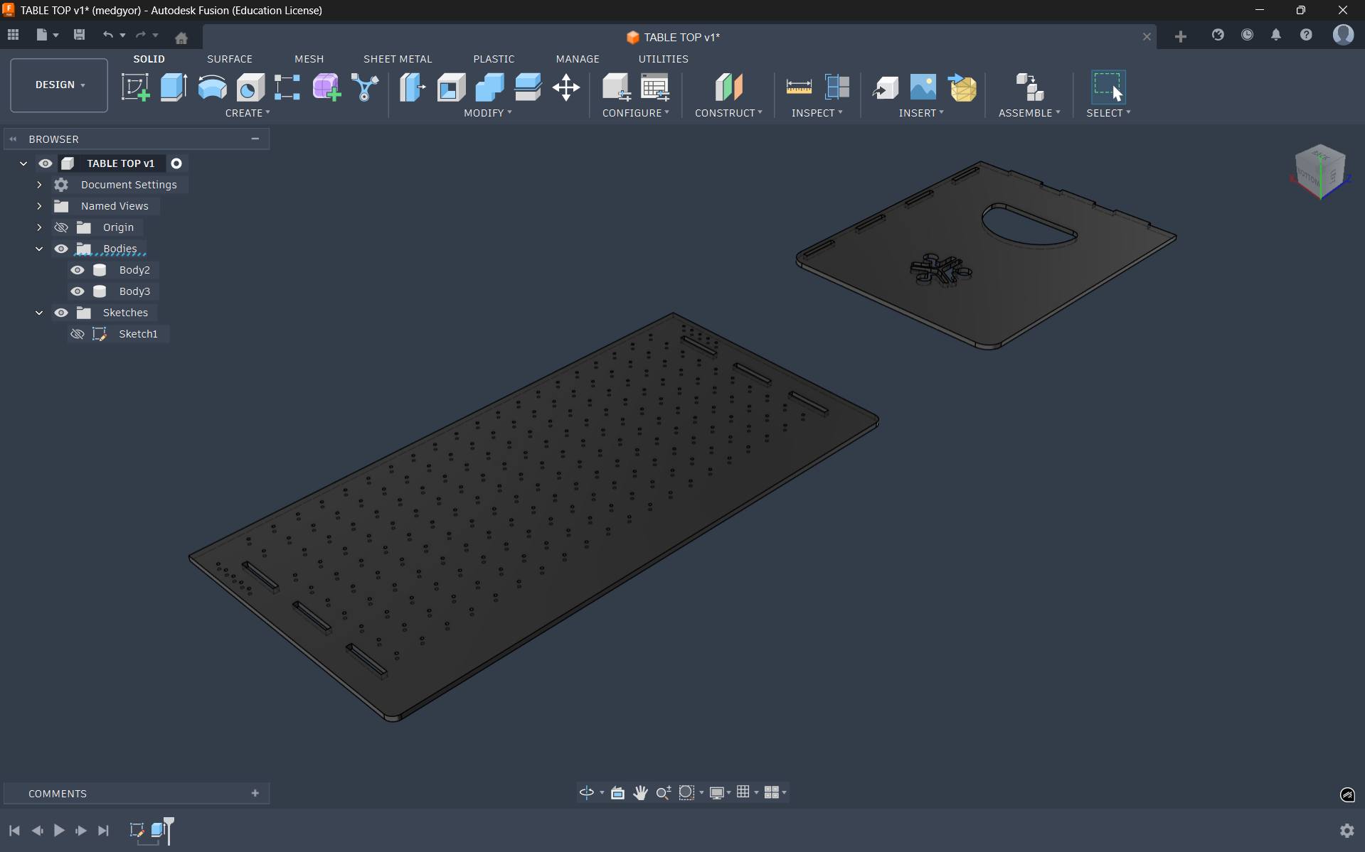
After that, I used the Extrude tool to extrude the plate with a parametric thickness value of 12 mm
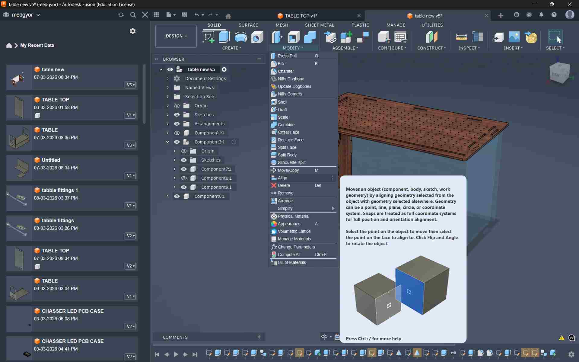
Using the Appearance tool, I applied colors to each component. Then I used the Move and Align tools to connect the table top with the legs.
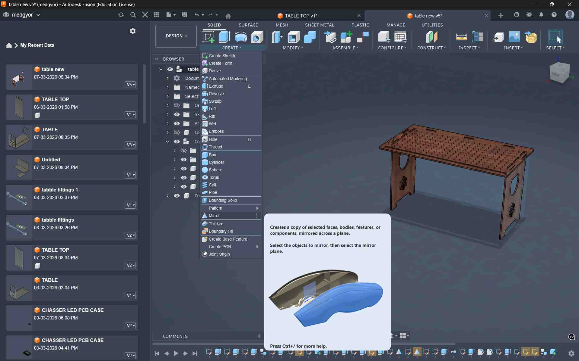
I used the Mirror option to duplicate the leg, and for that I created a mid-point plane.
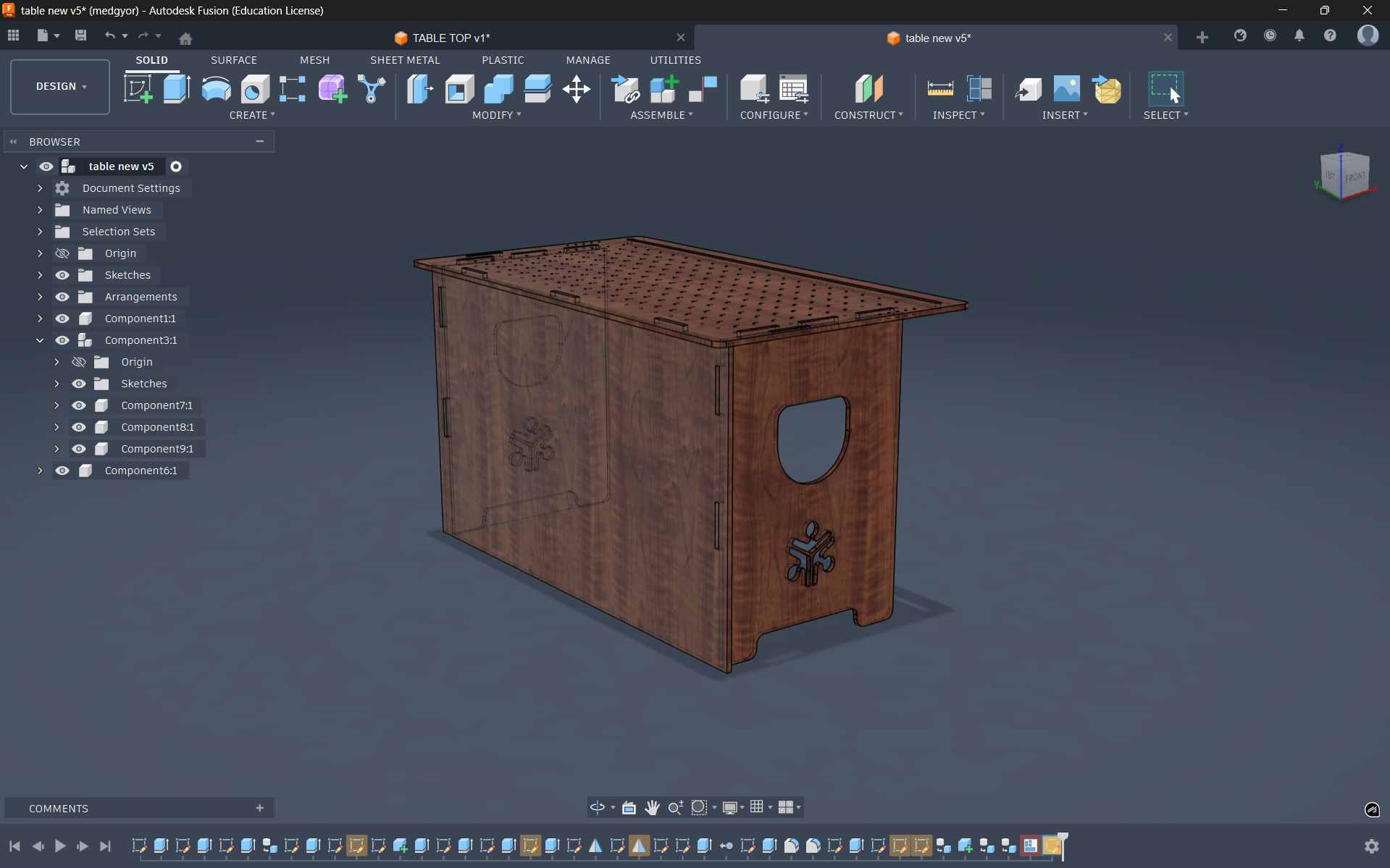
To improve stability and support, I added a back panel behind the table.
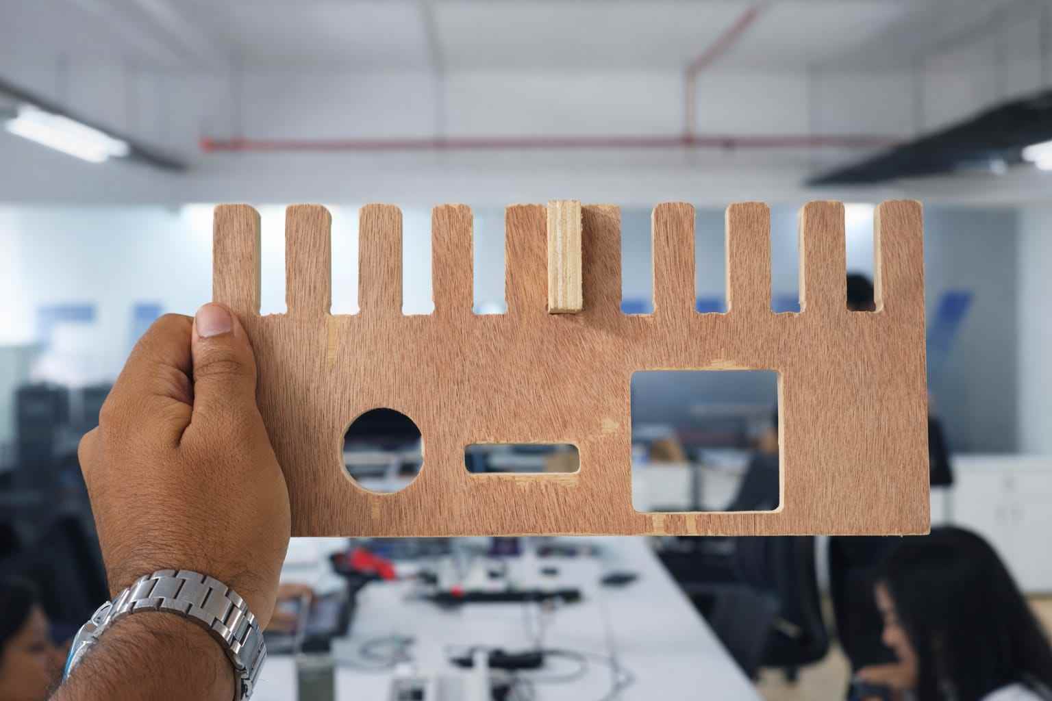
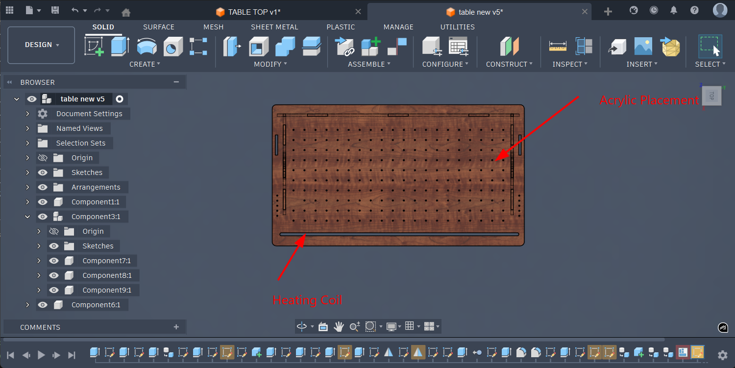
To bend the acrylic, I made a slot with a 5 mm depth to place the nichrome wire, which heats the acrylic and allows it to bend.
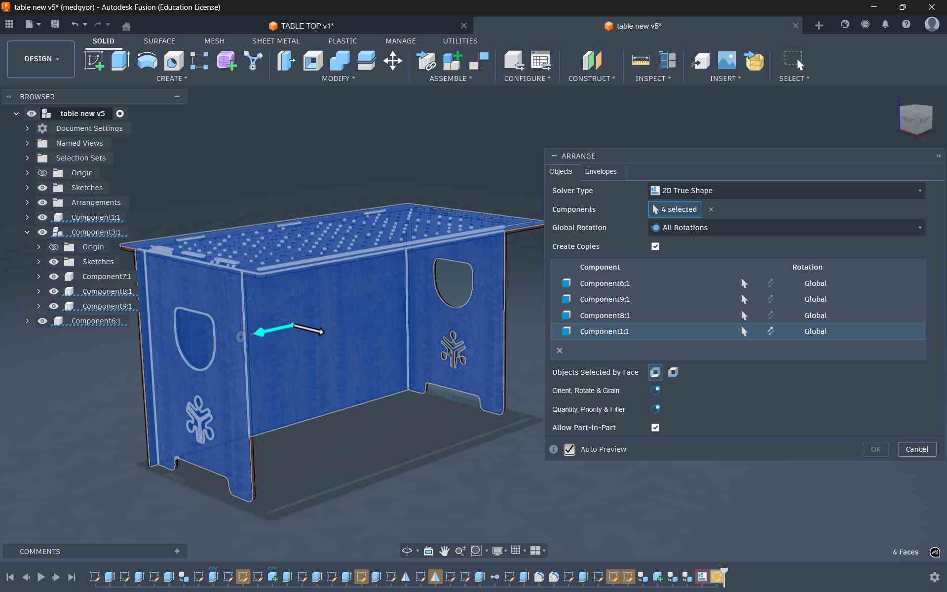
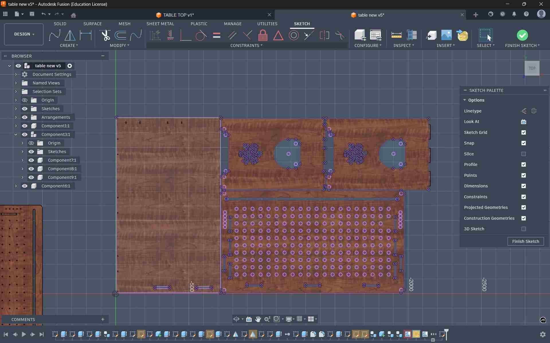
Select the faces of the body that need to be arranged on the plywood sheet.
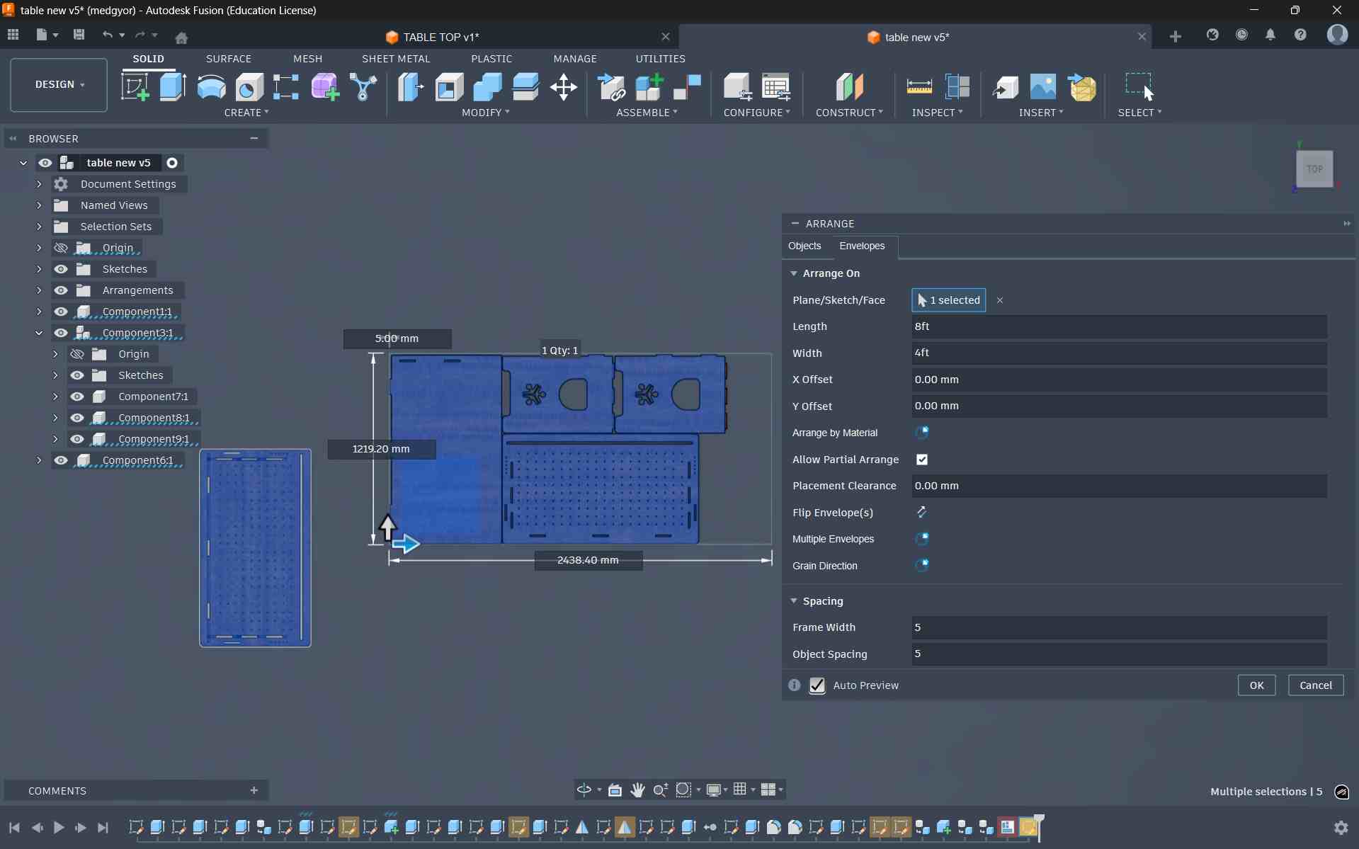
After that, I set the plywood length and breadth to 8 × 4 feet, and then defined the spacing between parts and the frame width
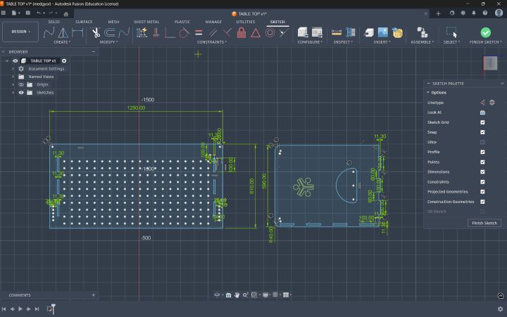
Cad modeling
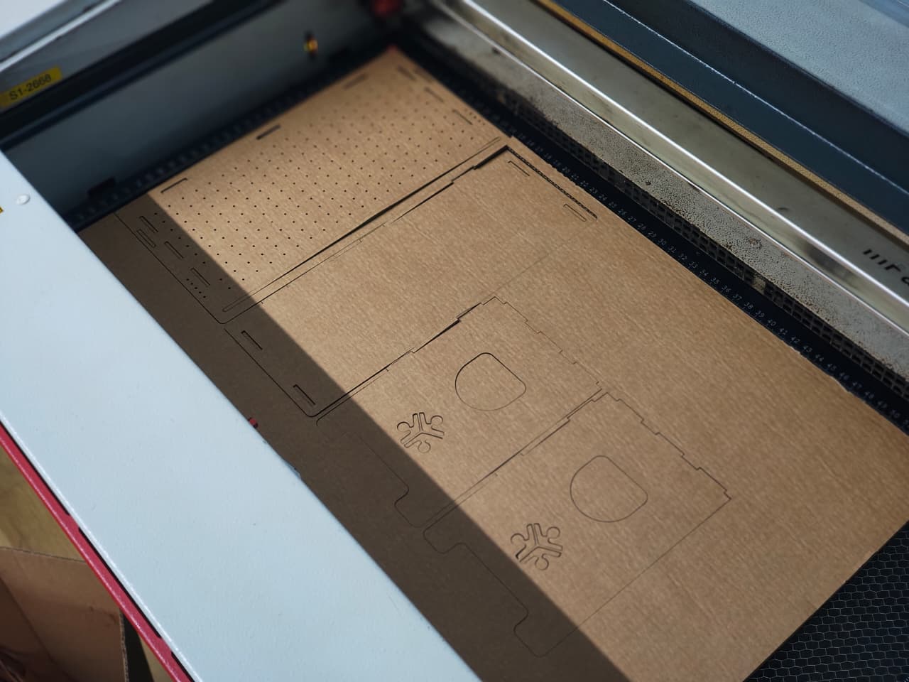
Laser-cut Cardboard Joinery Test Piece
Before proceeding with CNC machining on the ShopBot, it is important to test the joinery and assembly to ensure that the design fits properly and functions as intended. Since CNC milling consumes more time and material, performing a quick prototype test helps identify potential issues in advance. For this stage, I created a laser-cut test prototype using cardboard to evaluate the joinery of the modular storage unit. A sheet of 3 mm cardboard available in the lab was used for this purpose. The workflow followed the same process documented earlier during Week 3, where laser cutting was introduced. The design was exported as a DXF file, opened in Inkscape, and prepared for laser cutting using the cardboard cutting parameters established during the Week 3 group assignment.
Because the original design was created for 12 mm plywood, some adjustments were required for the cardboard prototype. The material thickness parameter was updated to approximately 2.6 mm, accounting for the compression and layered structure of the cardboard. After updating the parameter, the model was scaled and regenerated so that the joinery matched the new material thickness.
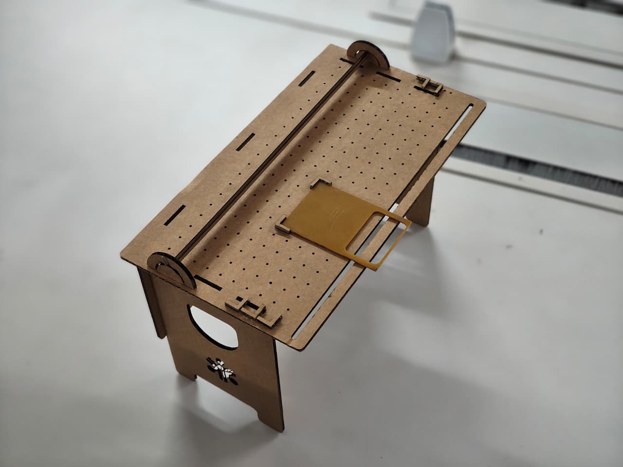
Since the joinery fit well and the structure assembled successfully, the design was validated and ready to move forward to the CNC machining stage using the ShopBot.
Adding Dogbone
Before preparing the design for CNC machining, it is necessary to add dogbone fillets to the internal corners of the slots. In CNC routing, the cutting tool is round, which means it cannot produce perfectly sharp 90-degree internal corners. In our case, the cutting tool used is a 6 mm end mill, which leaves a small radius at internal corners. This radius can prevent square-edged parts, such as tabs or tenons, from fitting properly into slots or mortises.
To solve this issue, dogbones are added. A dogbone is a small circular relief cut placed at the internal corners of a slot or pocket. This allows the mating part to fit completely into the corner despite the round cutting tool.
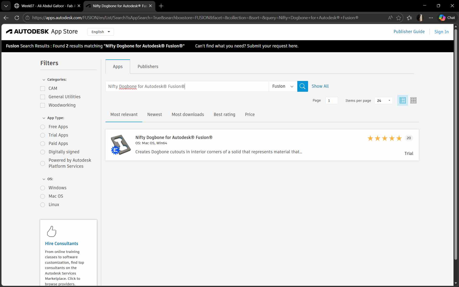
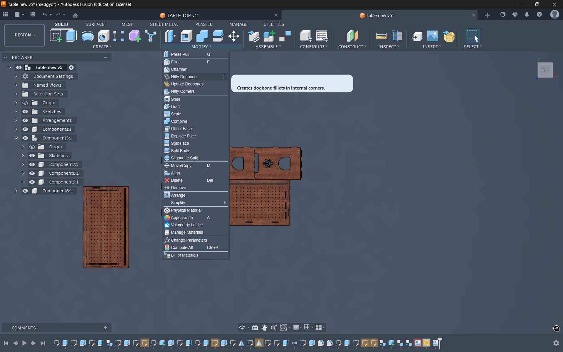
To create these dogbones, I installed a plugin from the Autodesk Fusion App Store called Nifty Dogbone for Autodesk Fusion. I downloaded the macOS version (trial) and installed it in Fusion. After installation, the tool appeared under the Modify menu as Nifty Dogbone.
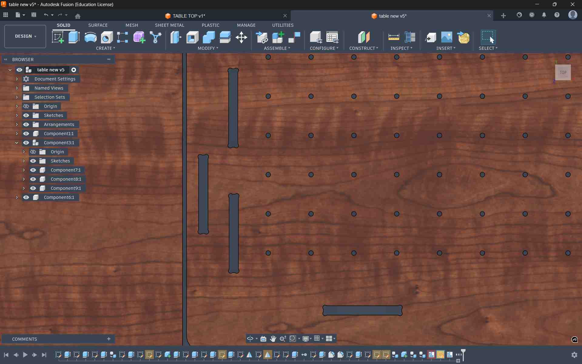
This is the final result after applying the dog bone fillets
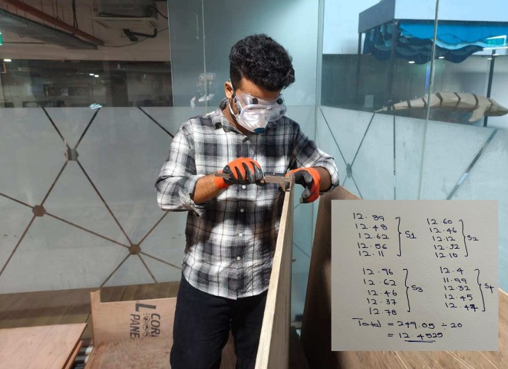
Checking Material Thickness
Adding Paramtric
Changing the Material Thickness Parameter
After obtaining this value, I updated the material thickness parameter in the Fusion model so that the joinery would match the actual material thickness.
Exporting for CAM
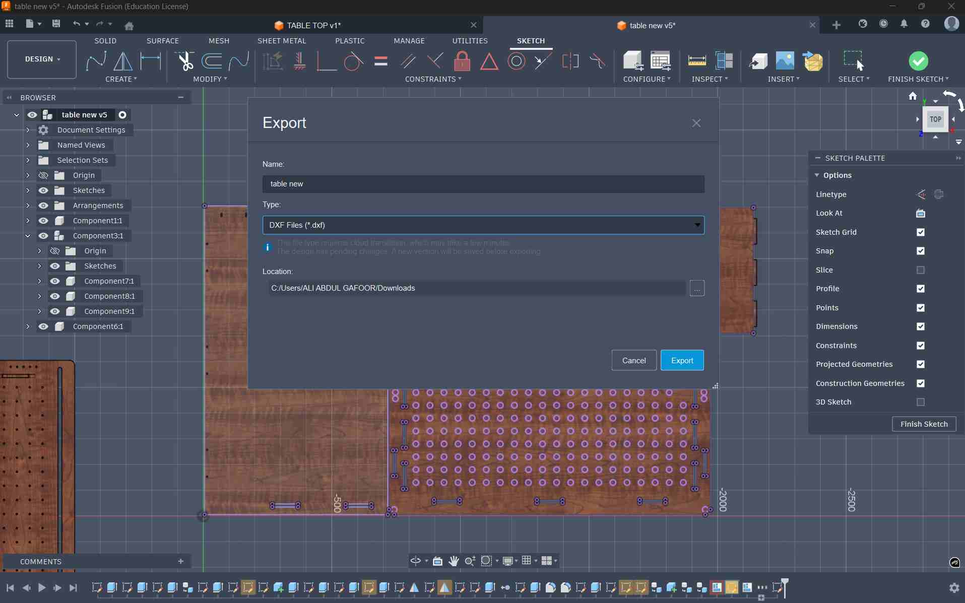
Once the thickness parameter was updated, I created a new sketch, projected the required profiles, and exported the geometry as a DXF file. This file would be used in the next step to prepare the CAM toolpaths for machining on the ShopBot CNC router.
Creating a new sketch and projecting to export dxf
Preparing the Machining Setup in VCarve
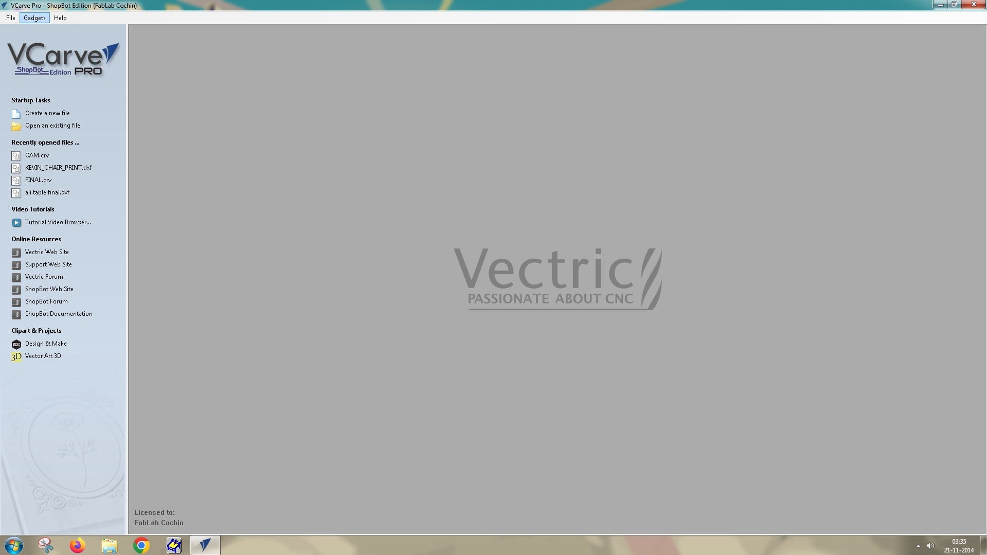
To prepare the design for CNC machining, I used VCarve Pro – ShopBot Edition, a CAD/CAM software specifically designed for ShopBot CNC machines. This software is used to generate the toolpaths that the machine will follow during the milling process.
After opening VCarve, I created a new file and set the job size according to the dimensions of the plywood sheet being used. The sheet size was 8 ft × 4 ft, which corresponds to approximately 2438 mm × 1219 mm. The material thickness was set to 12.4 mm, based on the average measurement obtained earlier from the plywood sheet. After entering these values, the workspace was created.
Next, I imported the design by going to File → Import Vectors and selecting the DXF file exported from Fusion 360. Sometimes the imported geometry does not appear centered on the workspace. To reposition it, the drawing can be selected and the Move tool can be activated by pressing M, allowing the design to be dragged and placed correctly within the working area.
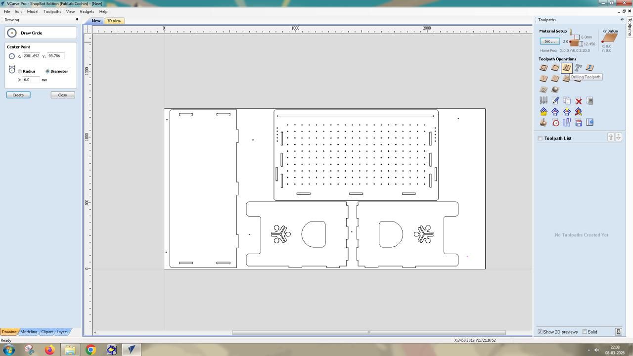
Planning Screw Locations
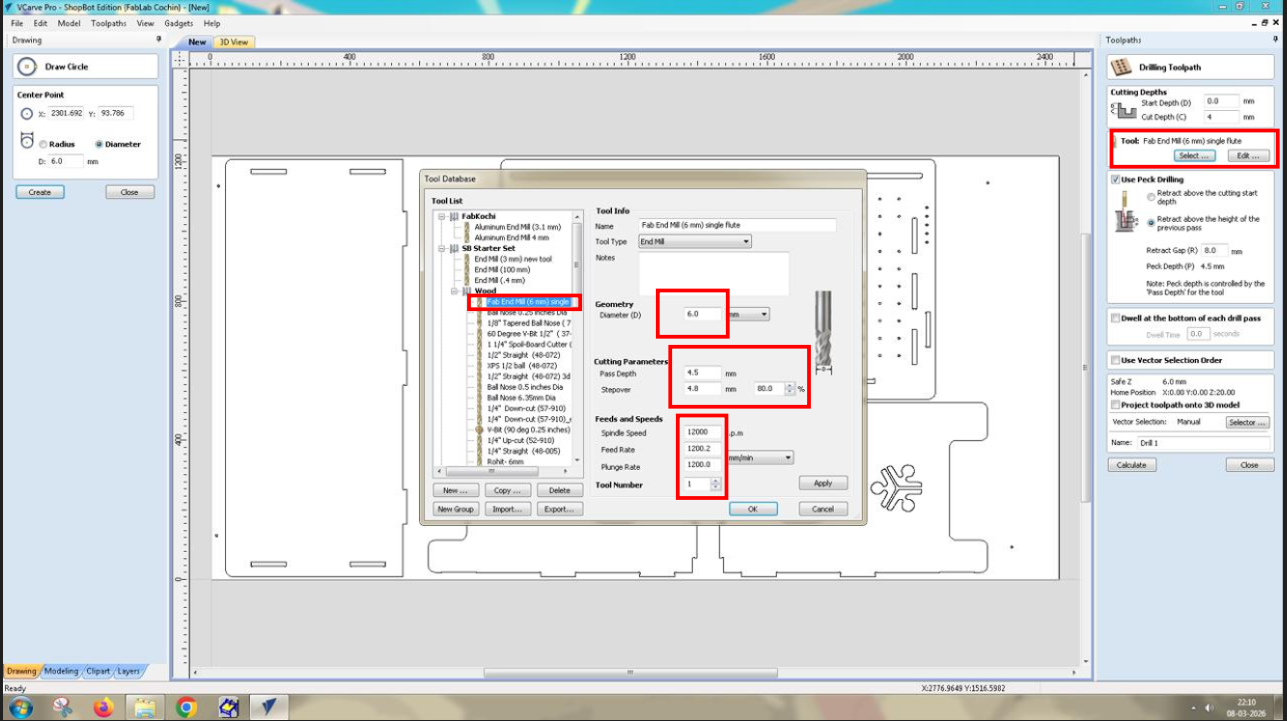
Select the Circle tool and set the diameter to 6 mm to mark the screw locations. These marks will be drilled manually later.
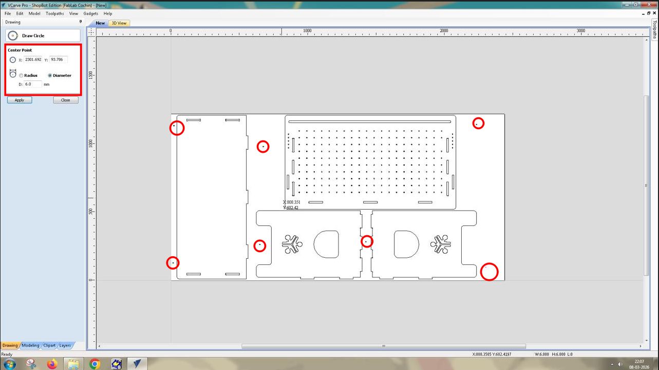
A drilling toolpath operation was then created in VCarve. The drilling operation was applied to these circles, but the depth was kept shallow so that the machine would only mark the positions rather than drill through the material. These marks serve as guides for manually drilling holes later, after which screws can be inserted to secure the sheet to the sacrificial layer
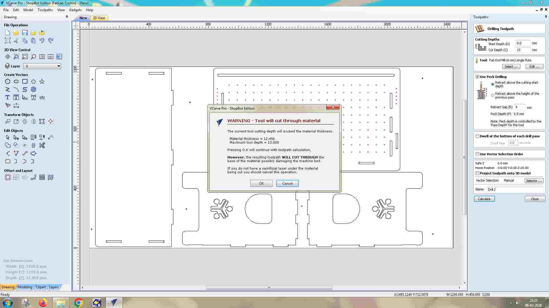
When calculating the toolpath, VCarve displays a warning indicating that the cut depth exceeds the material thickness. Since this was intentional, the warning was accepted and the toolpath preview was generated.
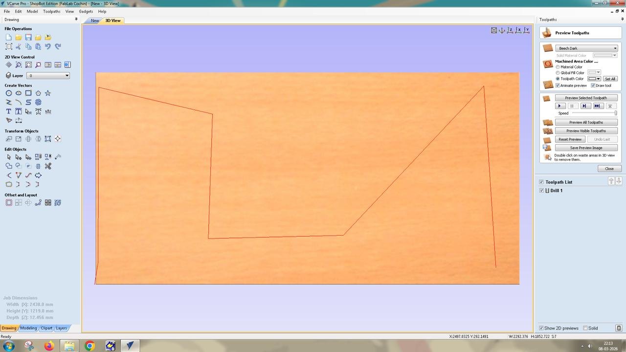
The toolpath preview can be viewed in two tabs:
Creating the Slot Cutting Toolpath
The second operation was the Profile Toolpath used to cut the internal slot features of the design. For this step, the slot vectors were selected and the machining option was set to Inside Cut, ensuring that the tool moves along the inner side of the vector so the slot dimensions remain accurate.
Some of the larger internal areas were also given holding tabs to prevent pieces from loosening during machining.
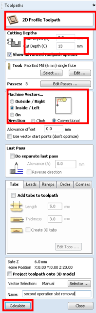
The tool used was a 6 mm single-flute end mill, with the feed rate set to 1200 mm/min. The start depth was set to 0 mm, since the tool begins cutting from the surface of the material. The cut depth was set to 13 mm, which is slightly deeper than the actual material thickness of 12.4 mm. This ensures the tool cuts completely through the plywood and slightly into the sacrificial layer, preventing incomplete cuts caused by small thickness variations in the material.
the tool cut depth (13 mm) is greater than the material thickness (12.4 mm), meaning the tool will cut through the material.
When calculating the toolpath, VCarve displays a warning indicating that the cut depth exceeds the material thickness. Since this was intentional, the warning was accepted and the toolpath preview was generated
Cutting the Outer Profile
The final operation was cutting the outer profile of each component. This was again created using a Profile Toolpath, but this time the machining option was set to Outside Cut, ensuring that the tool cuts along the outside of the vector so that the final part dimensions remain accurate.
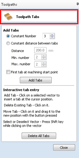
Holding tabs were added to these outer profiles to keep the parts attached to the sheet during machining. Without tabs, the parts could move or shift once they are fully cut.
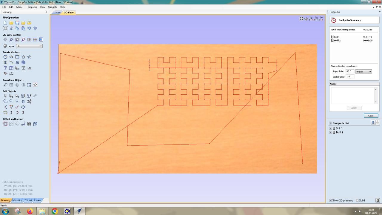
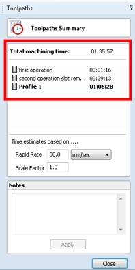
This is the list of toolpaths created for CNC machining.
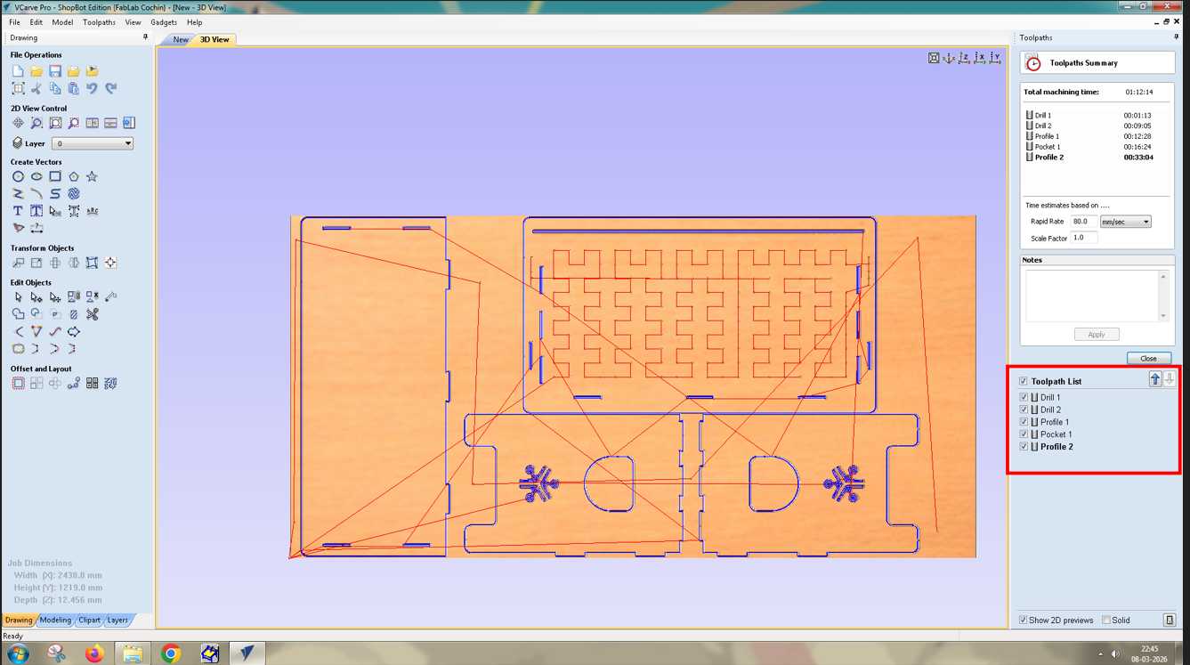
After calculating the toolpath, the preview showed the full machining sequence. The estimated machining time for the complete job was approximately 1 hour and 35 minutes.
Saving the Toolpaths
The toolpaths were exported as ShopBot Part Files (.SBP). The operations were saved as two separate files.
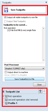
The first file contains the drilling operation, which marks the screw positions. After running this file on the machine, the holes are manually drilled and screws are inserted to secure the plywood sheet to the sacrificial layer.
The second file contains the remaining operations: the internal slot cutting and the outer profile cutting. Saving them separately ensures that the machining operations will not accidentally pass over the screw locations during cutting, which helps prevent tool collisions and possible end mill breakage.
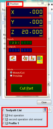
Running the Job on the ShopBot CNC
After completing the CAM preparation in VCarve, the next step was to run the job using the ShopBot command console. This interface allows control of the CNC machine and displays the X, Y, and Z axis positions, as well as the code that the machine executes during operation.
The first step before running any job is to set the origin (zero position) of the machine. Since a new plywood sheet had been placed on the machine bed, the origin used in the previous job would no longer be valid. Therefore, the machine coordinates needed to be reset.
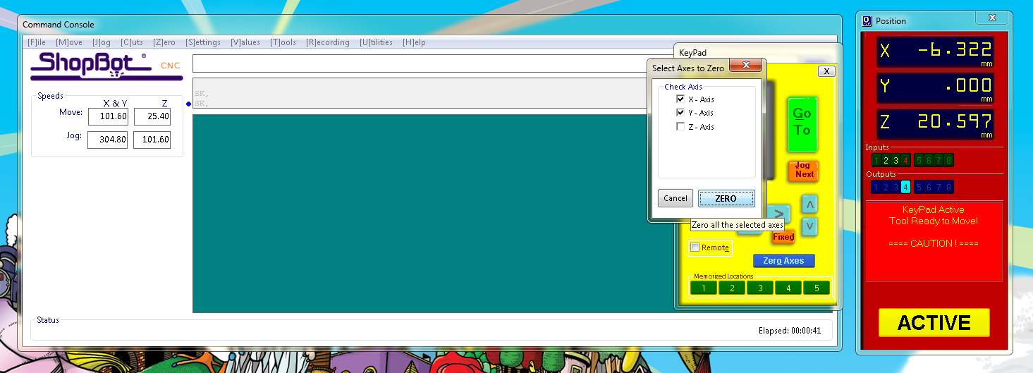
The X and Y origin were set by moving the spindle to the reference point using the ShopBot movement controls or keyboard arrow keys, then zeroing the axes. The Z-axis was set using a touch-off plate. An aluminum plate was placed under the tool and an alligator clip was attached to the end mill.
The X and Y origin were set by moving the spindle to the reference point using the ShopBot movement controls or keyboard arrow keys, then zeroing the axes. The Z-axis was set using a touch-off plate. An aluminum plate was placed under the tool and an alligator clip was attached to the end mill.
Once the operation was completed, the spindle was turned off. The marked positions were then manually drilled and screws were inserted, fastening the plywood sheet securely to the sacrificial layer underneath.
Resetting the Z Axis
After securing the sheet with screws, the Z-axis was reset again using the aluminum plate and alligator clip. This step ensures that any small changes in height caused by repositioning the sheet or tightening the screws do not affect the cutting depth during the next machining operations.
Running the First Operation – Marking Screw Locations
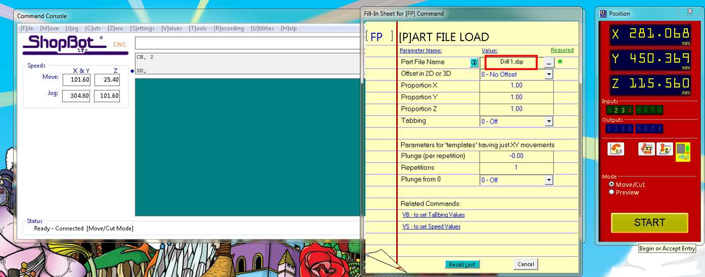
With the machine origin established, the first file generated in VCarve was loaded into the ShopBot software. This file contained the drilling operation used to mark the screw locations.
Before starting the job, the file name was verified to ensure that the correct operation was being executed. Once confirmed, the job was started from the console.
Running the Final Machining Operations
After resetting the Z-axis, the second file containing the remaining toolpaths was loaded. This file included both the internal slot cuts and the outer profile cut
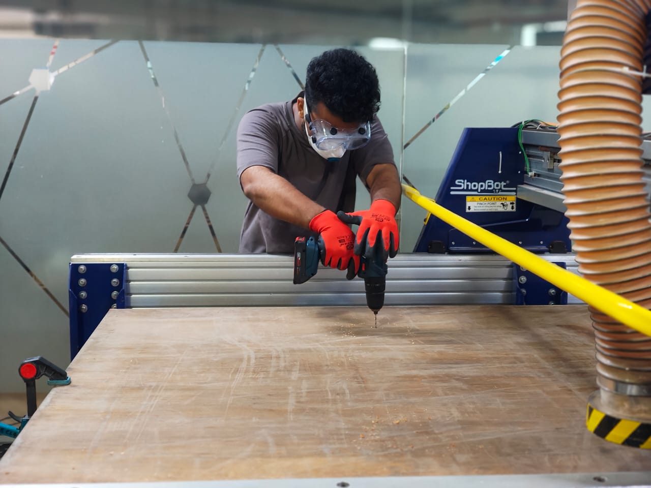
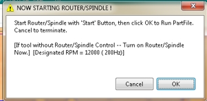
When running the machine, the spindle must be turned on manually using the spindle key. It is important to listen for the spindle sound to confirm that it is spinning correctly before proceeding. For this first operation, the vacuum system was intentionally kept off. This allowed the debris left by the drilling marks to remain visible, making it easier to identify the marked screw positions.
The machine then ran the drilling routine and created eight marked positions on the plywood sheet.
Post-Processing the Components
Once the parts were removed from the sheet, they were taken to the post-processing area, where several finishing steps were carried out.
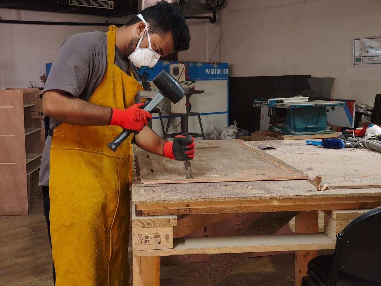
Removing Tab
After cutting, we need to separate the body from the sheet by removing and clearing all the tabshere i used chisel and mallet.
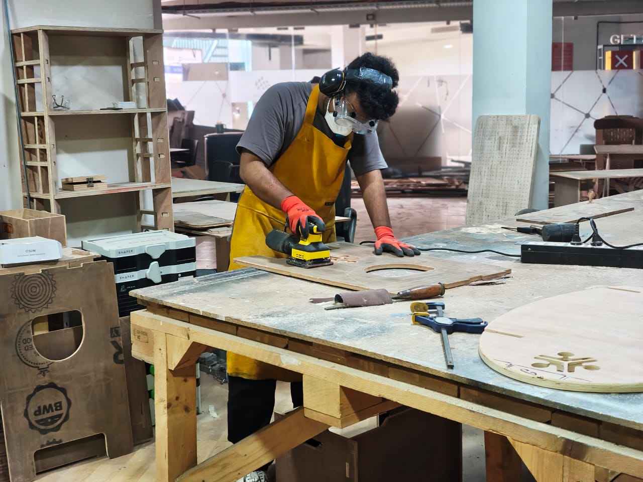
Sanding
Using an orbital sanding machine, I removed all the grains and excess material.
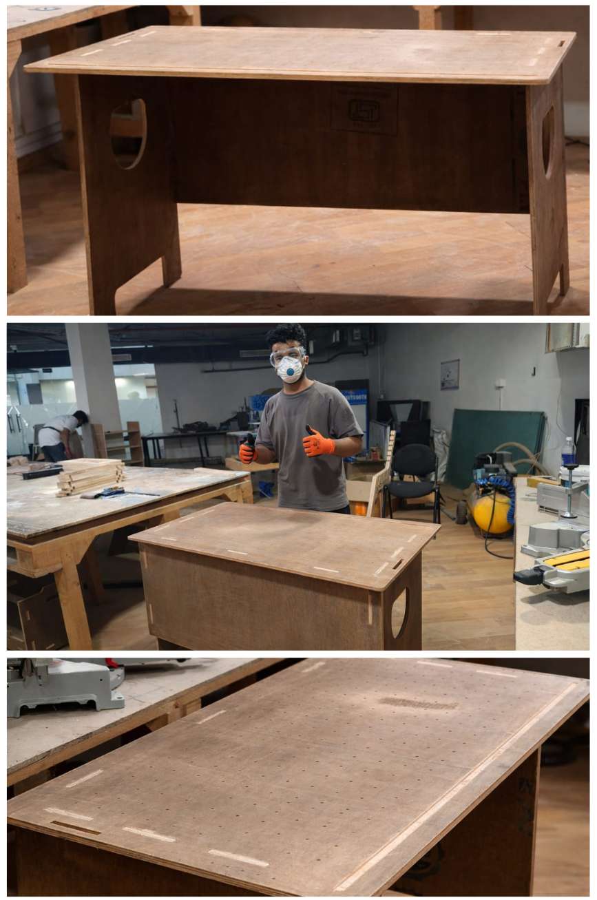
Assembly
After post-processing, I assembled all the parts together to make the table.
Acrylic Bending
For the acrylic branding process, I built a custom hot-wire cutting setup using a 24V, 14.6A SMPS to power a 0.8 mm Nichrome wire. The Nichrome wire was heated electrically to generate sufficient temperature for cutting and shaping the acrylic material accurately. This setup provided stable heating and enabled clean branding and fabrication of the acrylic components used in the project.
Acrylic Bending Process Using Nichrome Wire
To bend the acrylic sheet, I first switched on the 24V, 14.6A SMPS, which supplied power to the 0.8 mm Nichrome wire. As current passed through the wire, it heated up and created a narrow heating zone for the bending operation.
The acrylic sheet was then positioned directly above the Nichrome wire. Care was taken to ensure proper alignment and that the distance between the acrylic sheet and the Nichrome wire was as small as possible without allowing them to touch. Maintaining this gap helped achieve uniform heating along the desired bend line while preventing damage to the acrylic surface.
After a short period of heating, the acrylic became soft and flexible enough for bending. Once the required flexibility was achieved, the sheet was carefully removed and placed into a custom mold to obtain the desired shape.
A suitable weight was then applied to hold the acrylic firmly in the mold while it cooled. After sufficient cooling time, the acrylic retained its new shape and was removed from the mold.
Finally, the power supply was switched off, completing the acrylic bending process.