WEEK 05 3D Scanning and 3D Printing
Objectives
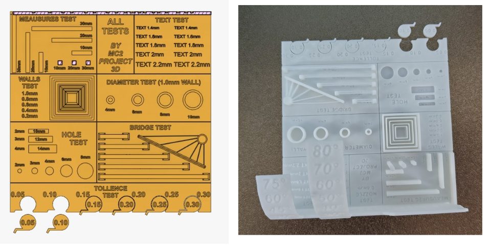
Group assignment: - test the design rules for your 3D printer(s)
To design and 3D print a small object (few cm³) that cannot be manufactured using subtractive methods, demonstrating the advantage of additive manufacturing.
Group Assignment
This week's assignments are divided into group and individual work. As a group, we will test the design rules and limitations of our 3D printers to understand their capabilities and constraints. Individually, I will design, document, and 3D print a small object (a few cubic centimeters) that cannot be made using subtractive manufacturing methods. I will also 3D scan an object and optionally explore printing the scanned model.
key Areas Covered:
To know more, visitGroup Assignment.
Individual Assignment
Design and 3D Print an Object That Cannot Be Made Subtractively
3D PRINTING:
3D Printing, also known as additive manufacturing, is a process of creating three-dimensional objects by depositing material layer by layer based on a digital model. Unlike traditional subtractive manufacturing methods, which remove material through cutting, drilling, or milling, 3D printing constructs objects from the bottom up. This approach significantly reduces material waste and allows the creation of complex geometries and internal structures that are difficult or impossible to achieve using conventional manufacturing techniques.
How it works ?
 Reserch Gate.
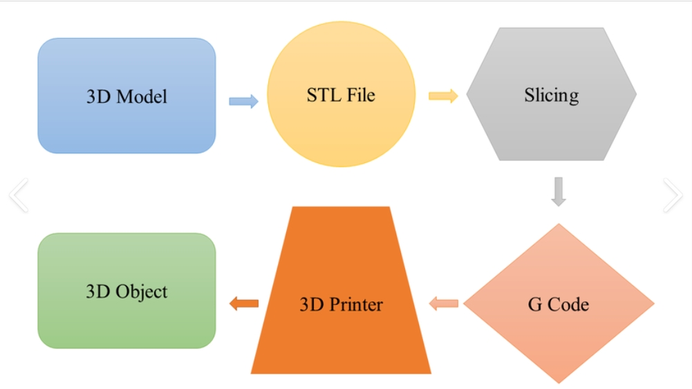
1. Designing the Model
2. Slicing the Model
The exported 3D file is imported into slicing software.
The slicer:
The final output is a machine-readable file (G-code or equivalent), which is sent to the 3D printer.
3. Printing Process
The 3D printer fabricates the object by depositing or solidifying material layer by layer, following the sliced instructions.
Depending on the printer technology, various materials can be used, including:
This layer-by-layer fabrication enables the creation of complex geometries and internal structures that are not possible with traditional subtractive manufacturing.
Post-Processing
After printing, the object may require cleaning, curing, or additional finishing, such as sanding or painting, to enhance its appearance and functionality.
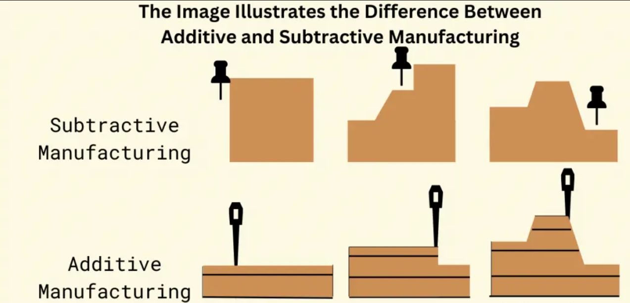
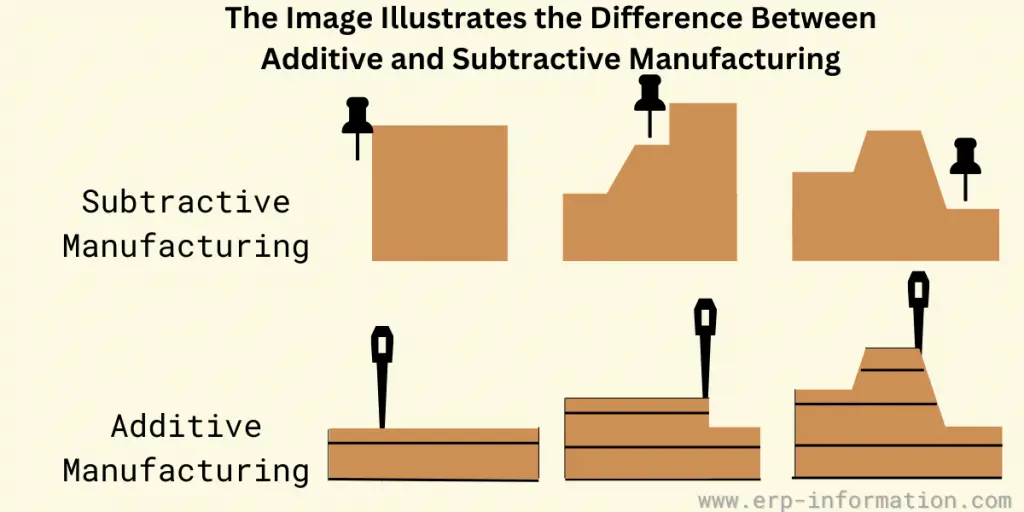
Additive manufacturing vs Substractive manufacturing
Subtractive manufacturing shapes an object by removing material, while additive manufacturing constructs it by gradually adding layers of material. Subtractive methods have been in use for a longer time and are typically faster, making them well-suited for high-volume production. In contrast, additive manufacturing allows for the creation of intricate designs, such as hollow or nested structures, which are challenging or even impossible to achieve with subtractive techniques
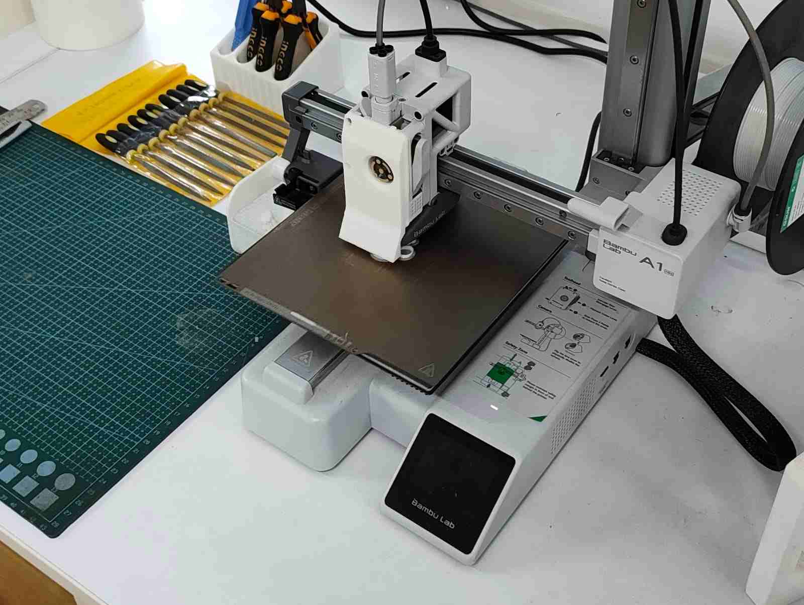
Bambu Lab A1
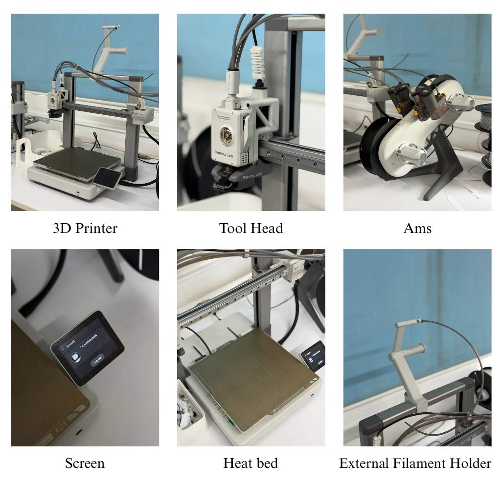
The Bambu Lab A1. is a high-speed Core XY 3D printer , offering smart automation features like auto Z-offset, auto flow calibration, auto belt tensioning, and real-time flow rate compensation.
The A1 features several smart automation functions that simplify the printing process, including:
The Bambu Lab A1 includes several smart automation features that simplify printing, such as Auto Z-Offset, Auto Flow Calibration, Auto Belt Tension, and Auto Vibration Calibration, ensuring accurate and high-quality prints. It also supports automatic filament loading, filament run-out detection, and power-loss recovery for reliable operation. The printer offers multi-color printing with the optional AMS Lite system and has a build volume of 256 × 256 × 256 mm³. It supports materials like PLA, PETG, and TPU, and features an easy-to-use touchscreen with both cloud and offline LAN modes. Overall, the A1 reduces manual calibration and makes 3D printing more efficient and user-friendly.
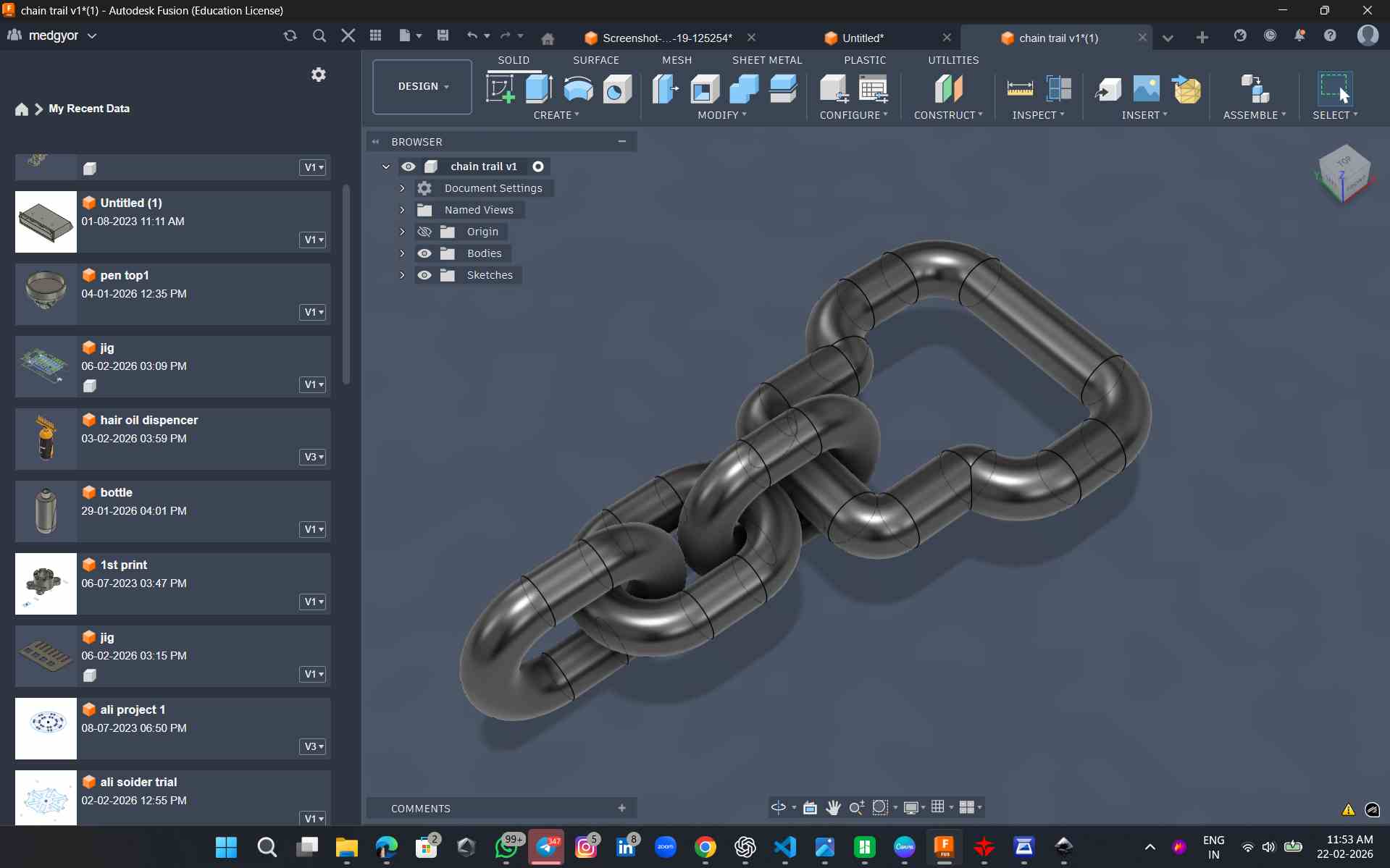
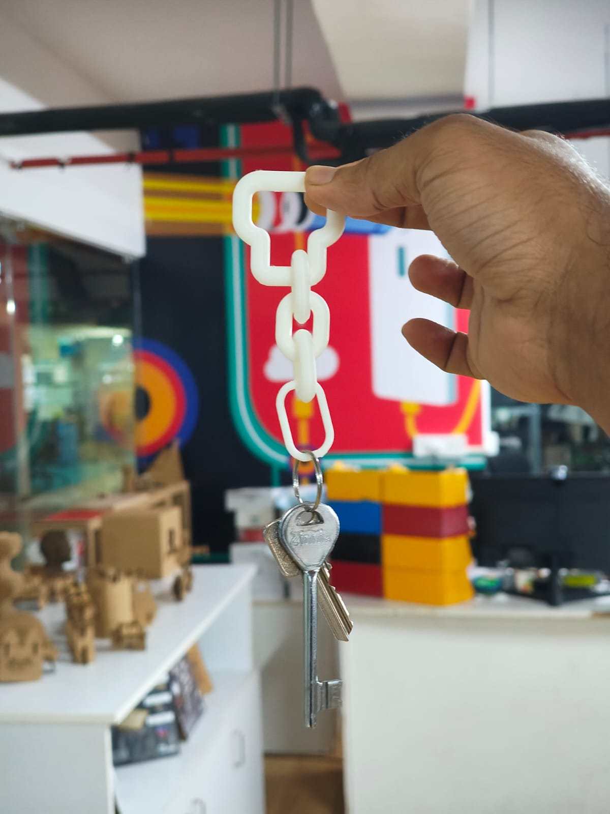
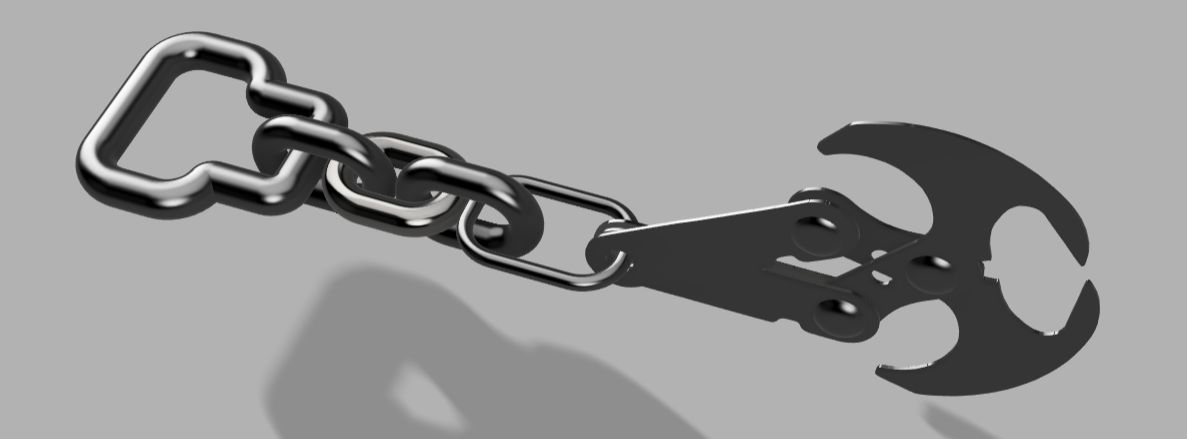
Design 1:chain-style keychain
For my individual assignment, I designed a chain-style keychain that looks like a normal steel chain.
This design cannot be manufactured using subtractive methods because:
Design Specifications
Small Chain Link
Large Chain Link
The links are modeled with rounded corners to:
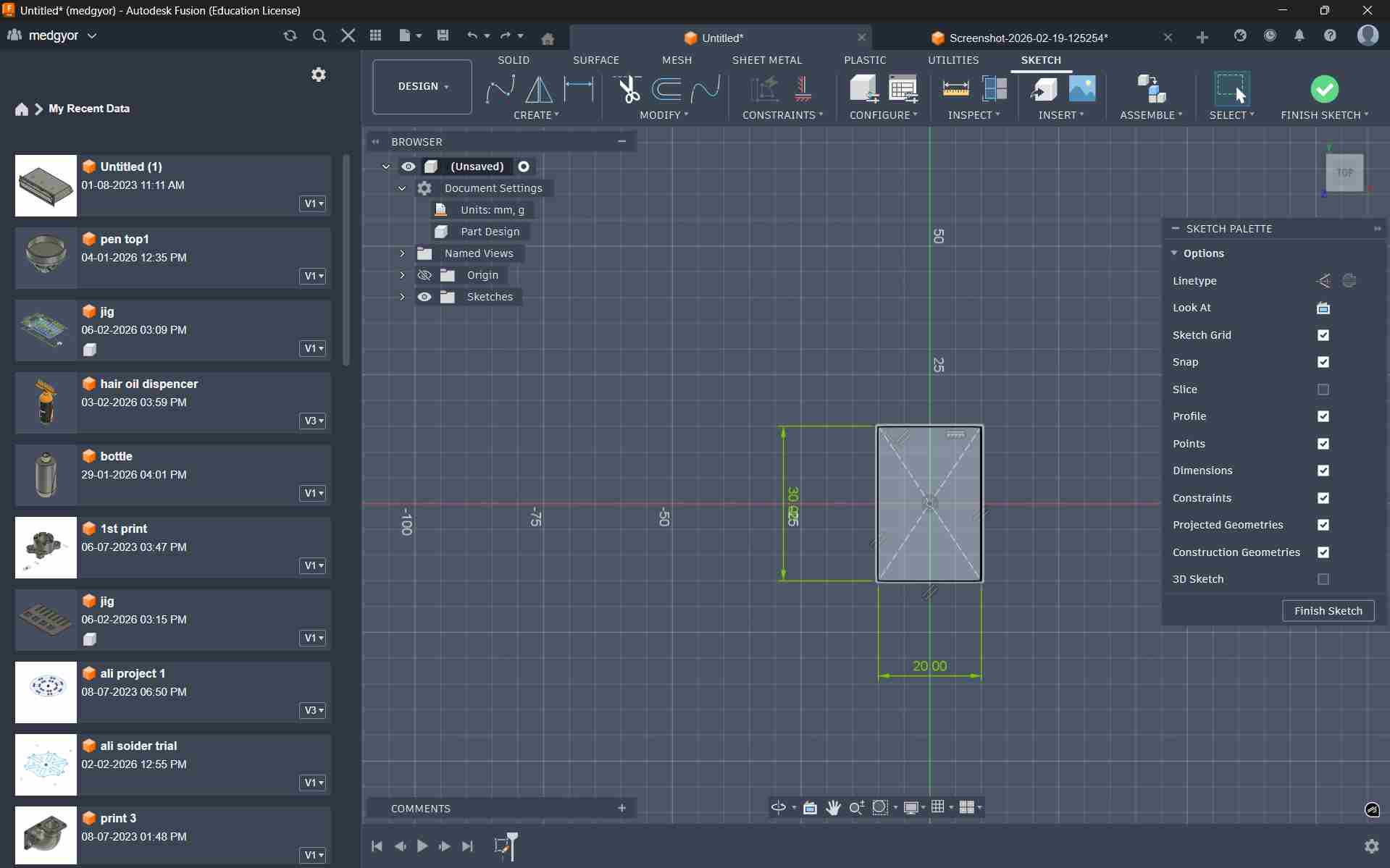
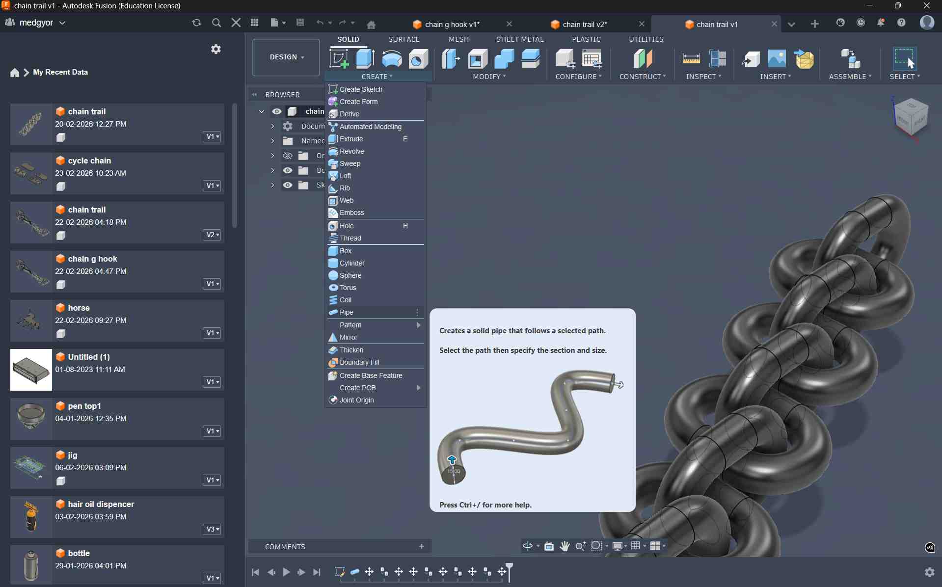
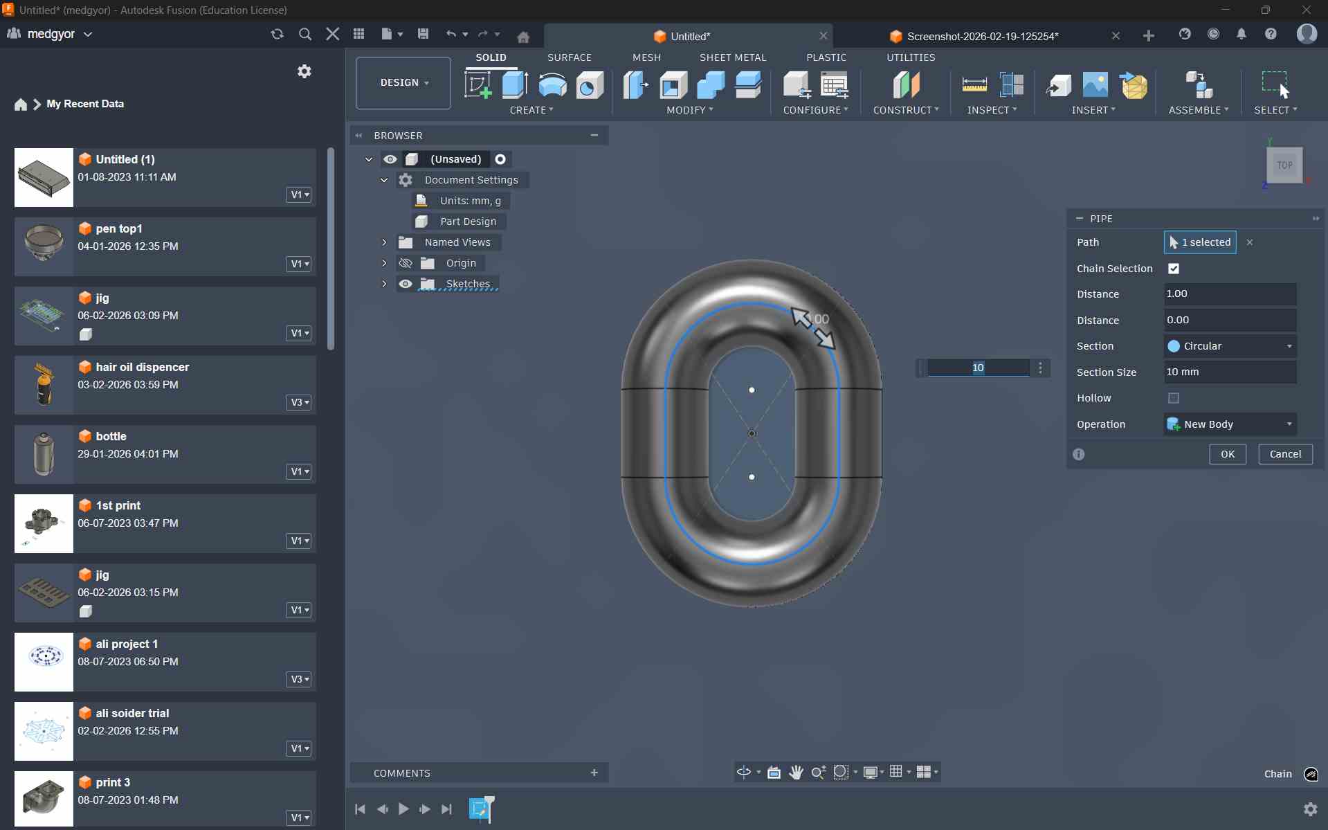
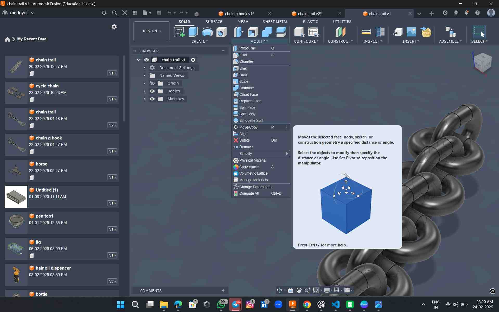
Using the Pipe tool in Fusion 360, I created a single chain ring by applying a circular profile along a sketched path.
In the Pipe tool, I set the thickness to 10 mm to achieve the required strength and structure for the design.
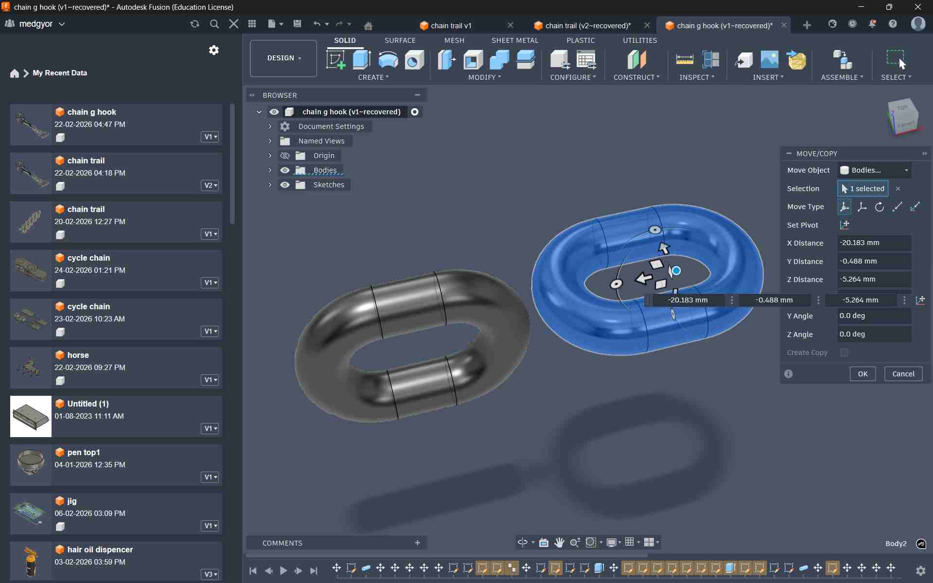
Using the Move/Copy tool in Fusion 360, I duplicated the chain ring to create four interconnected rings.
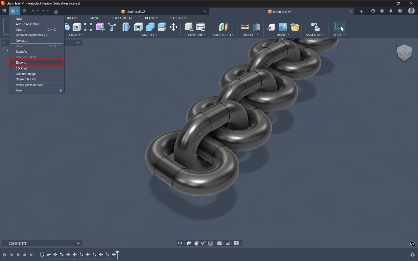
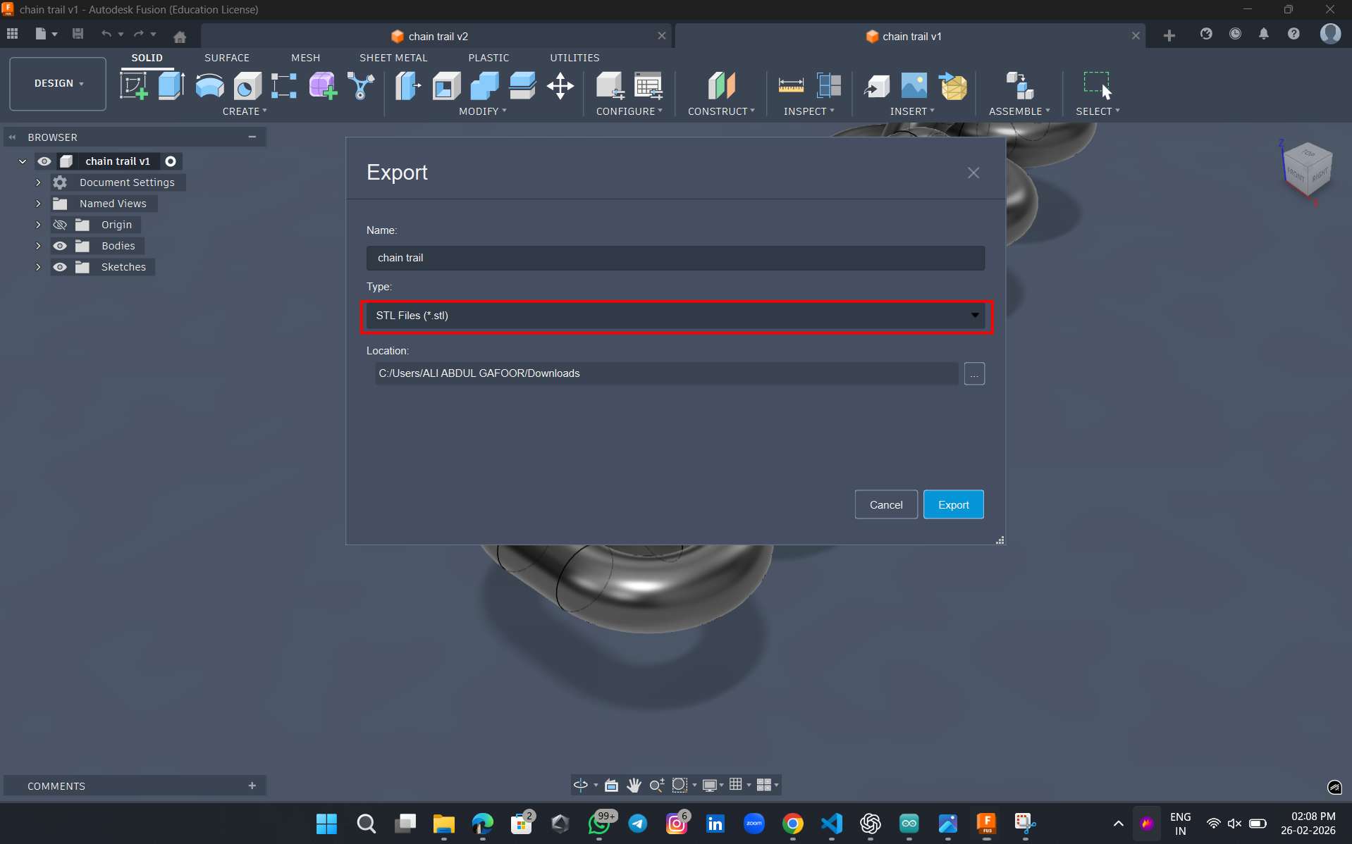
The image is then exported as a stl file. For the slicer, I downloaded Bambu Studio software
I opened the file in the software
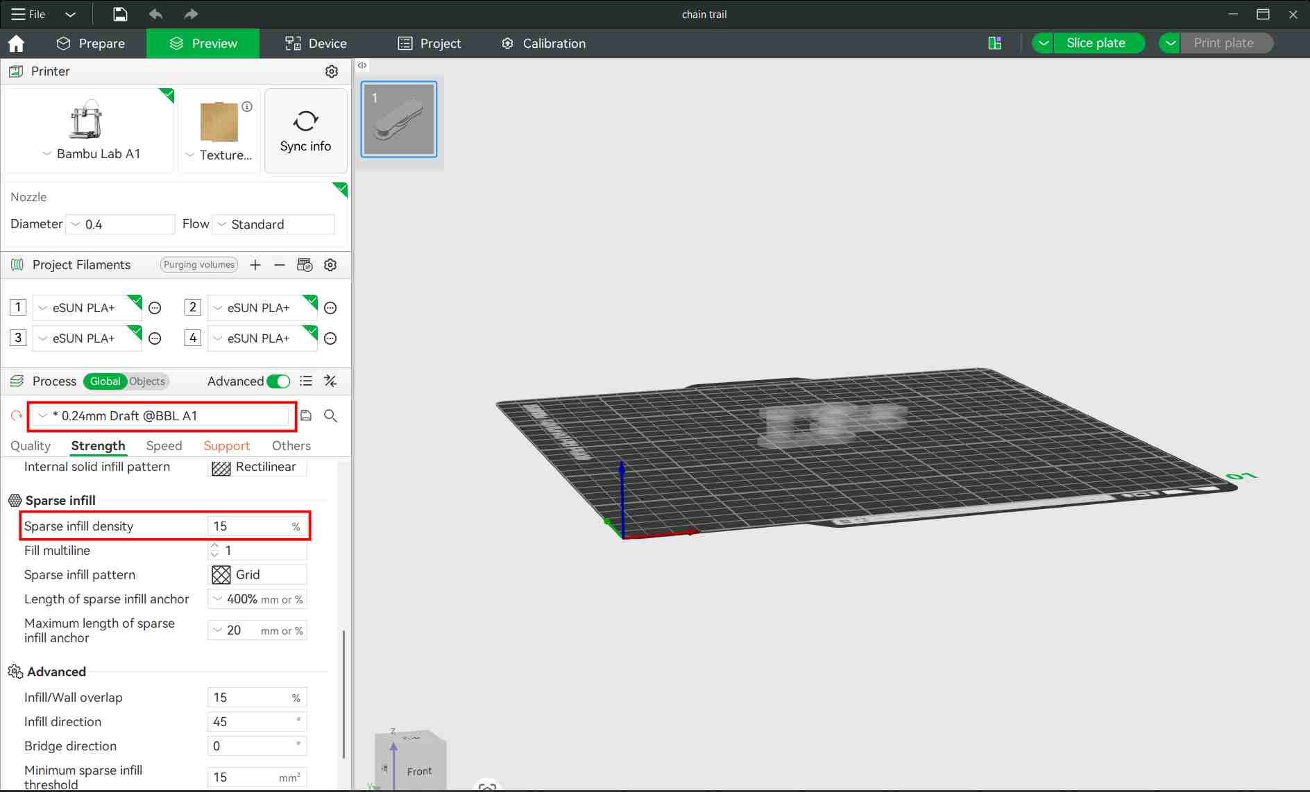
Bambu Studio was used to prepare the 3D models for printing. It slices the model into layers and generates the G-code required by the 3D printer. Print settings such as layer height, infill, and supports were adjusted using the software.
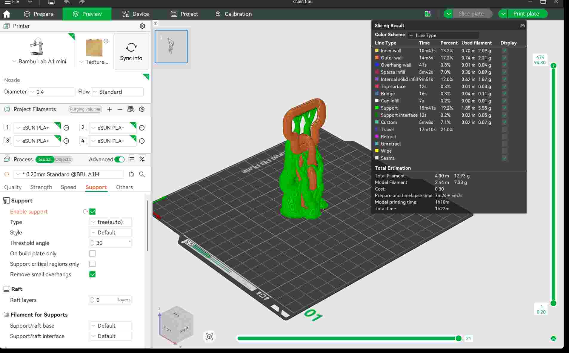
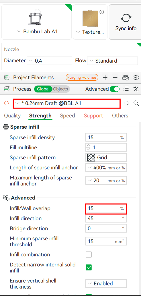
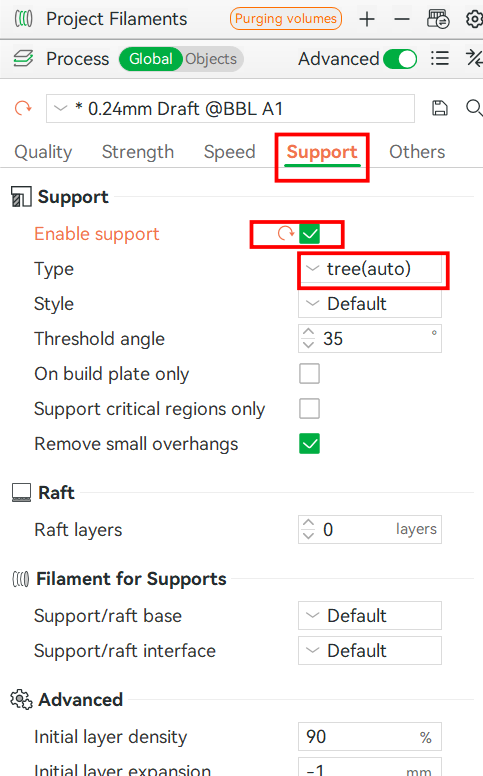
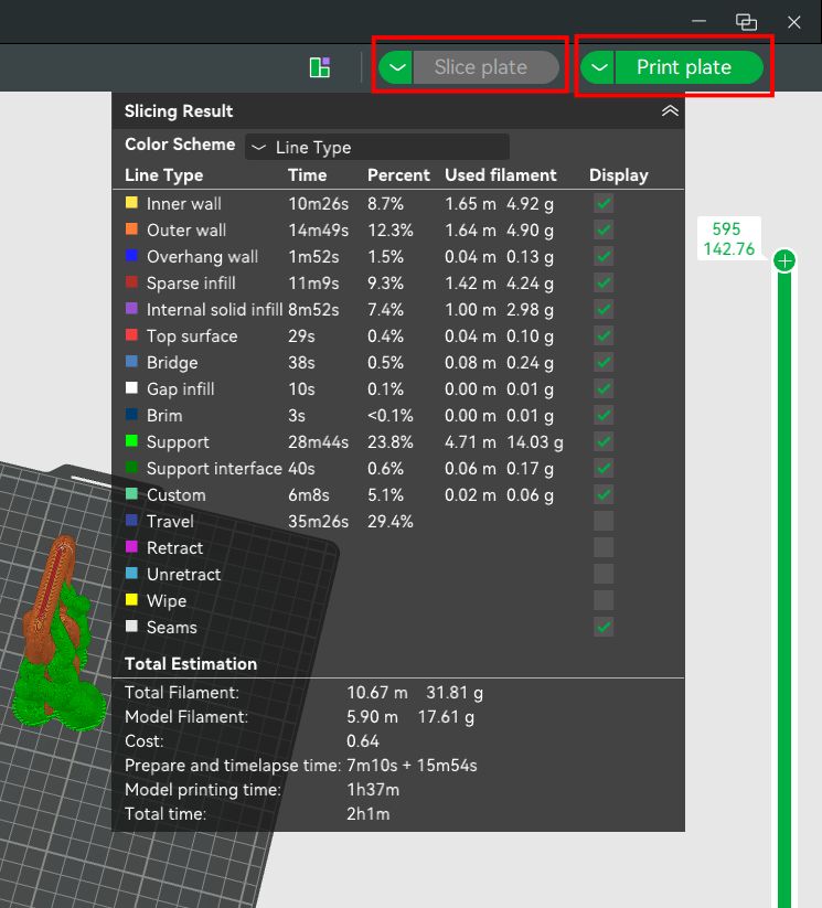
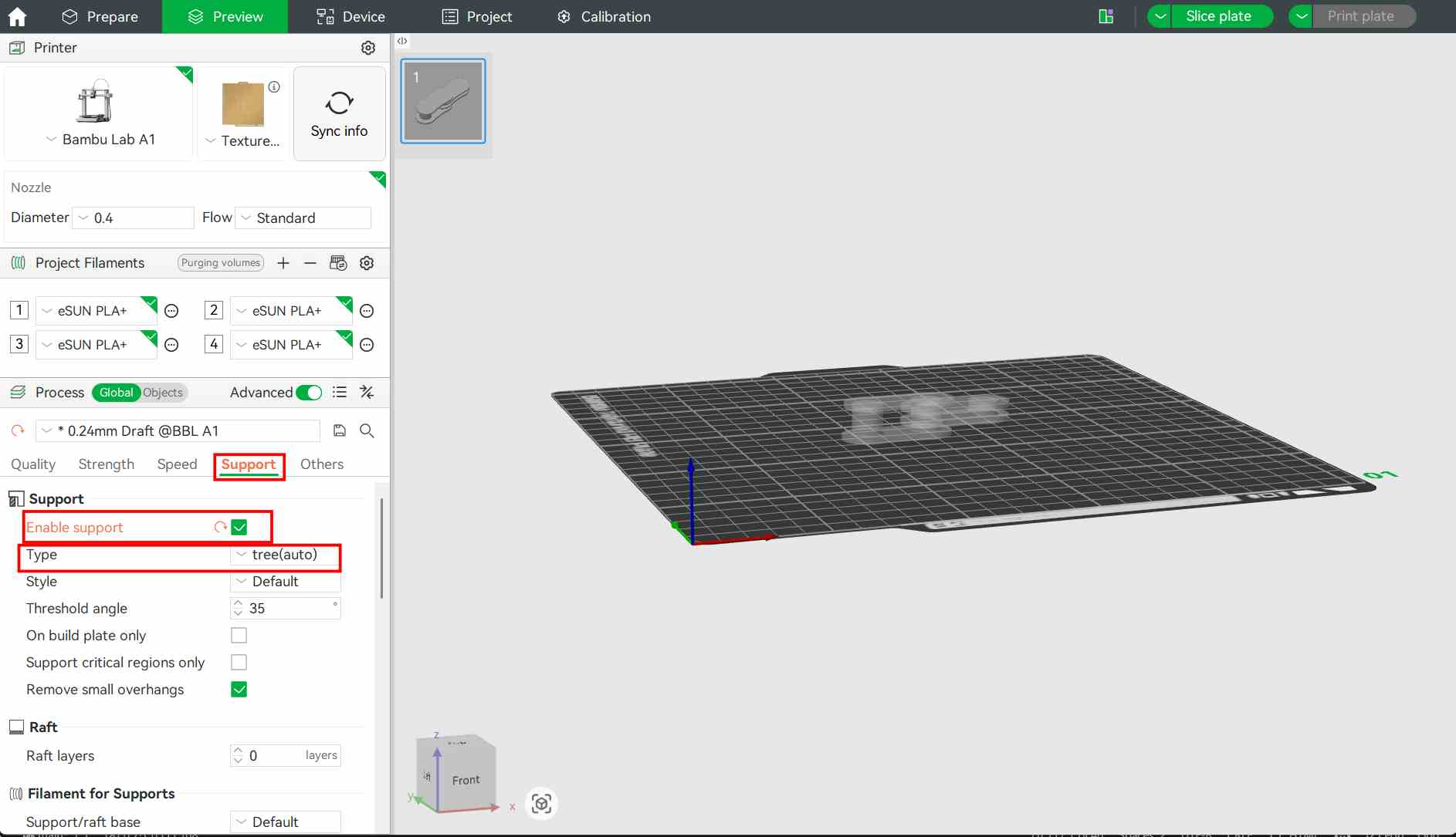
The support was selected as tree type and infill as 15. Random seam was selected. Layer height was selected as 0.24mm
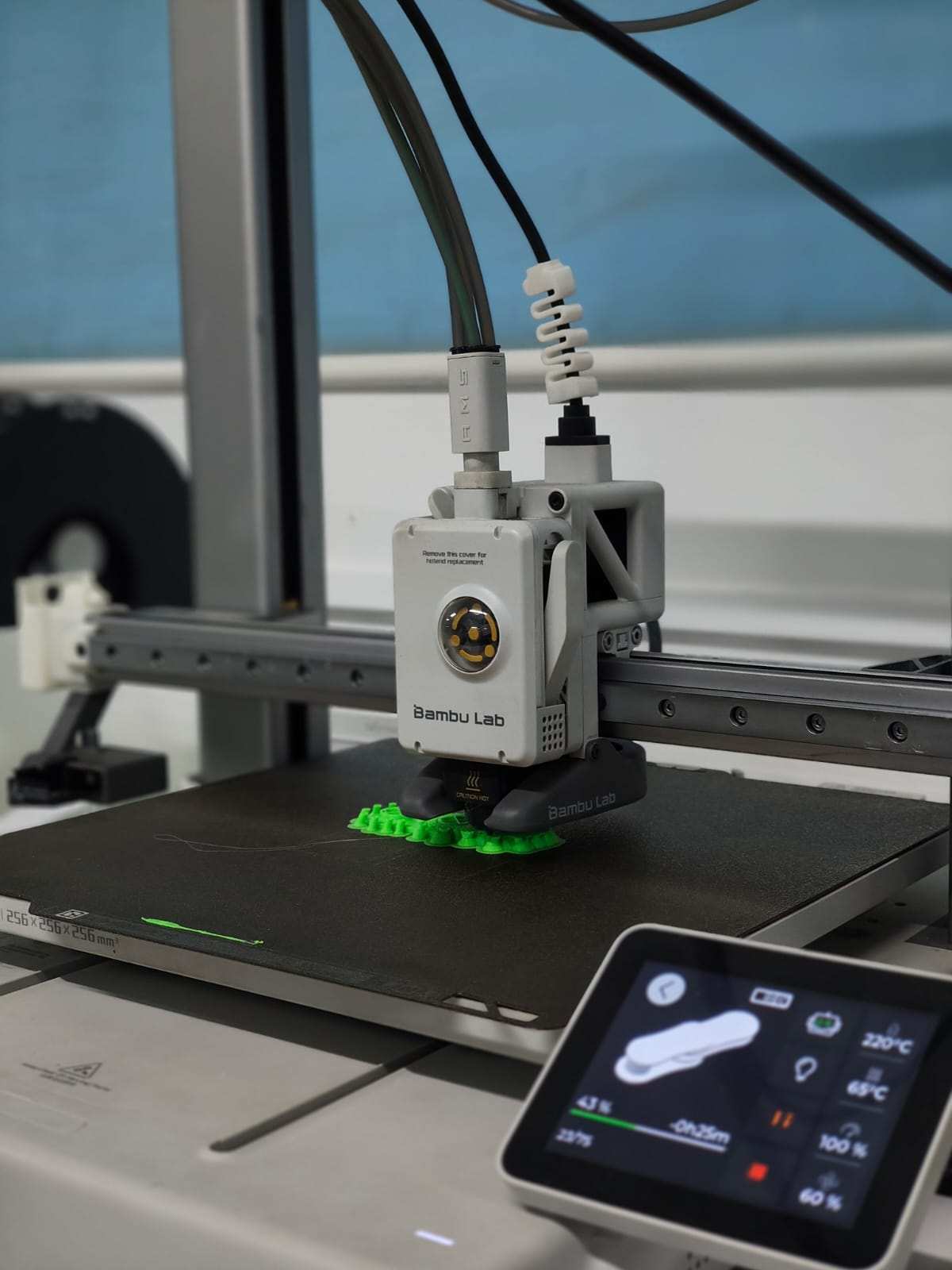
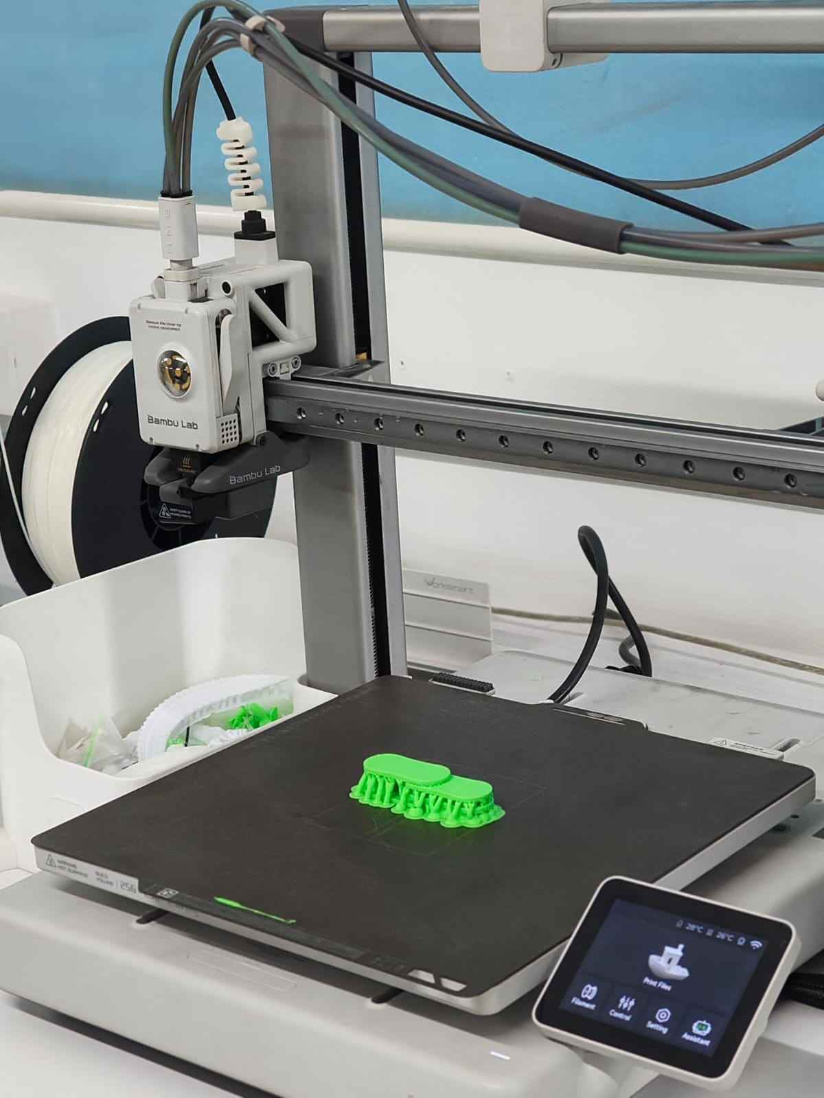
After making necessary changes, select print plate and select the printer in it. Select send. Then the job is fed to the printer
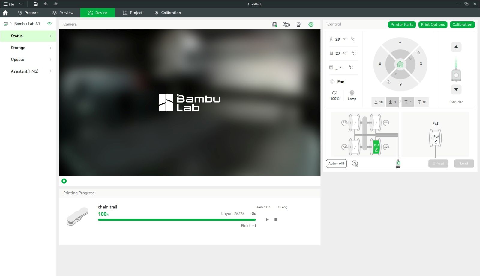
Then a window opens showing the printing page. The print status and camera feed can be seen on this page
For support I selected tree type. Infill was 15. To select infill, strength → infill. I selected 0.24 mm as layer height. Select slice plate. After making necessary changes select print plate. Select the 3d printer and connect. Once the calibration is complete, printing process will start.
For post-processing, I did not require any special tools. It was simple and easy to remove the supports manually.
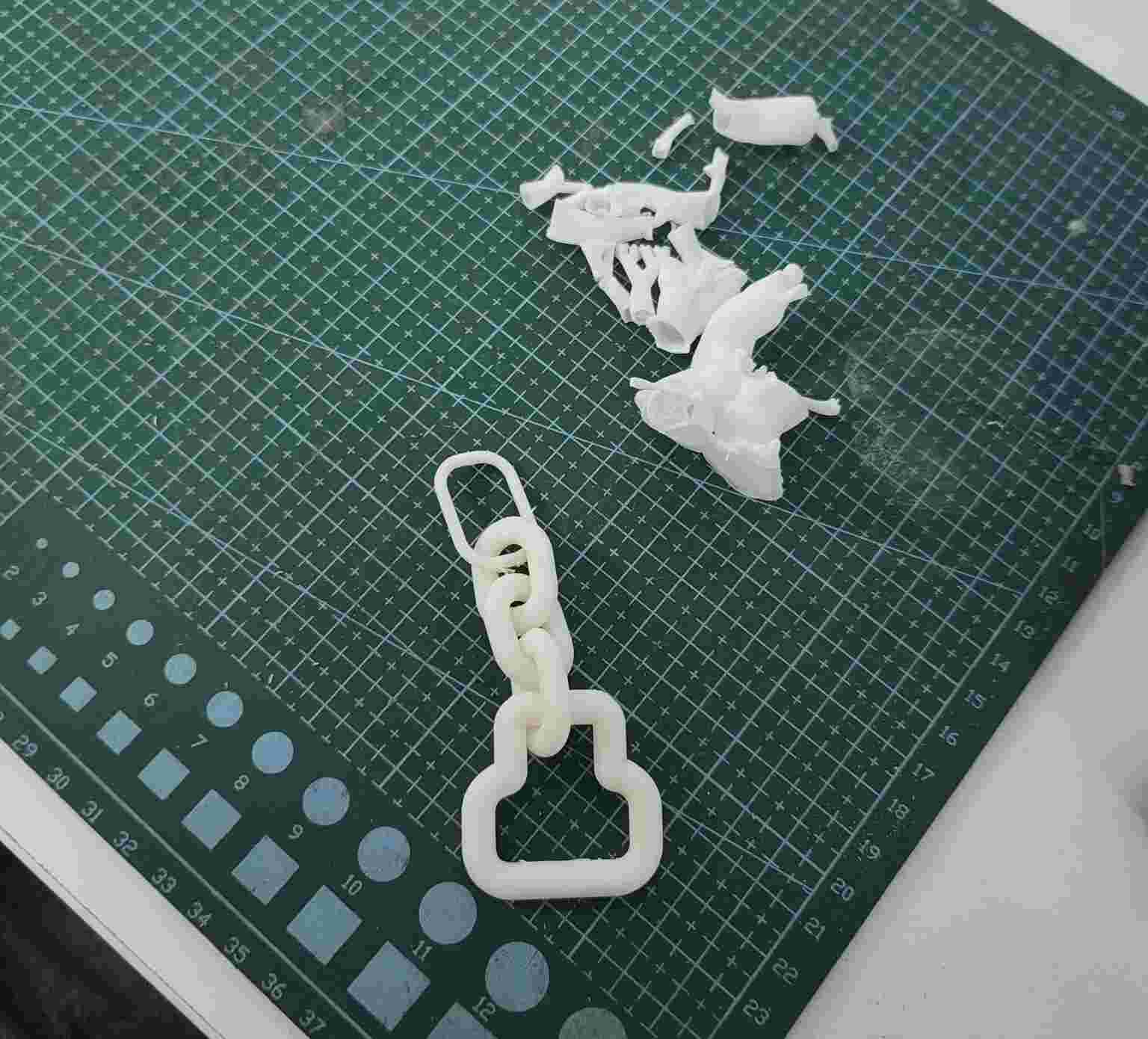
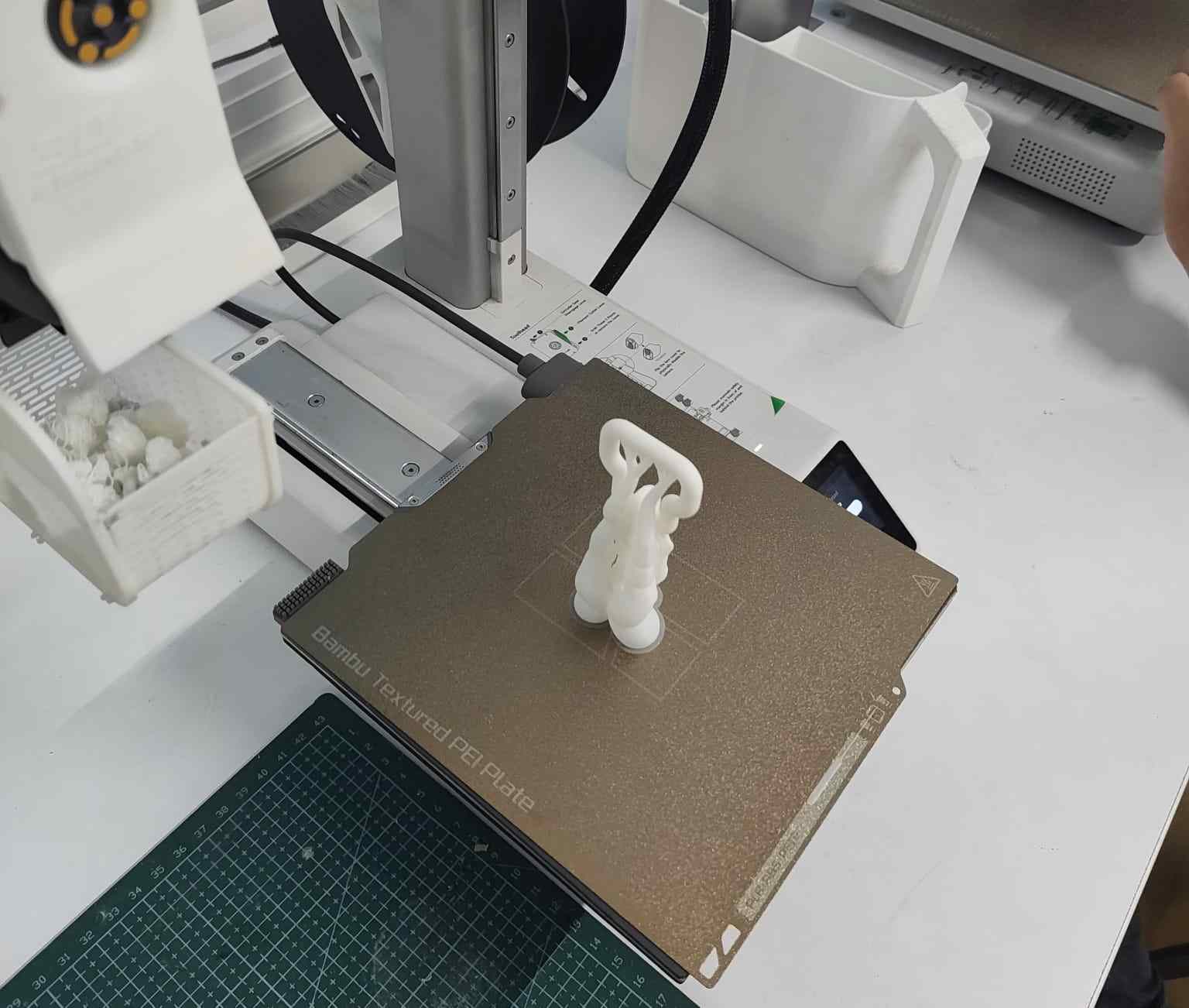
Hero Shot:01
My instructor Saheen pointed out that this design could be made using CNC milling, meaning it could be produced by subtractive manufacturing or even hand-crafted through sculpting. So, I redesigned the model in Autodesk Fusion 360 and created a motorcycle-style chain with interlocking links printed in one piece, which cannot be made using subtractive methods.
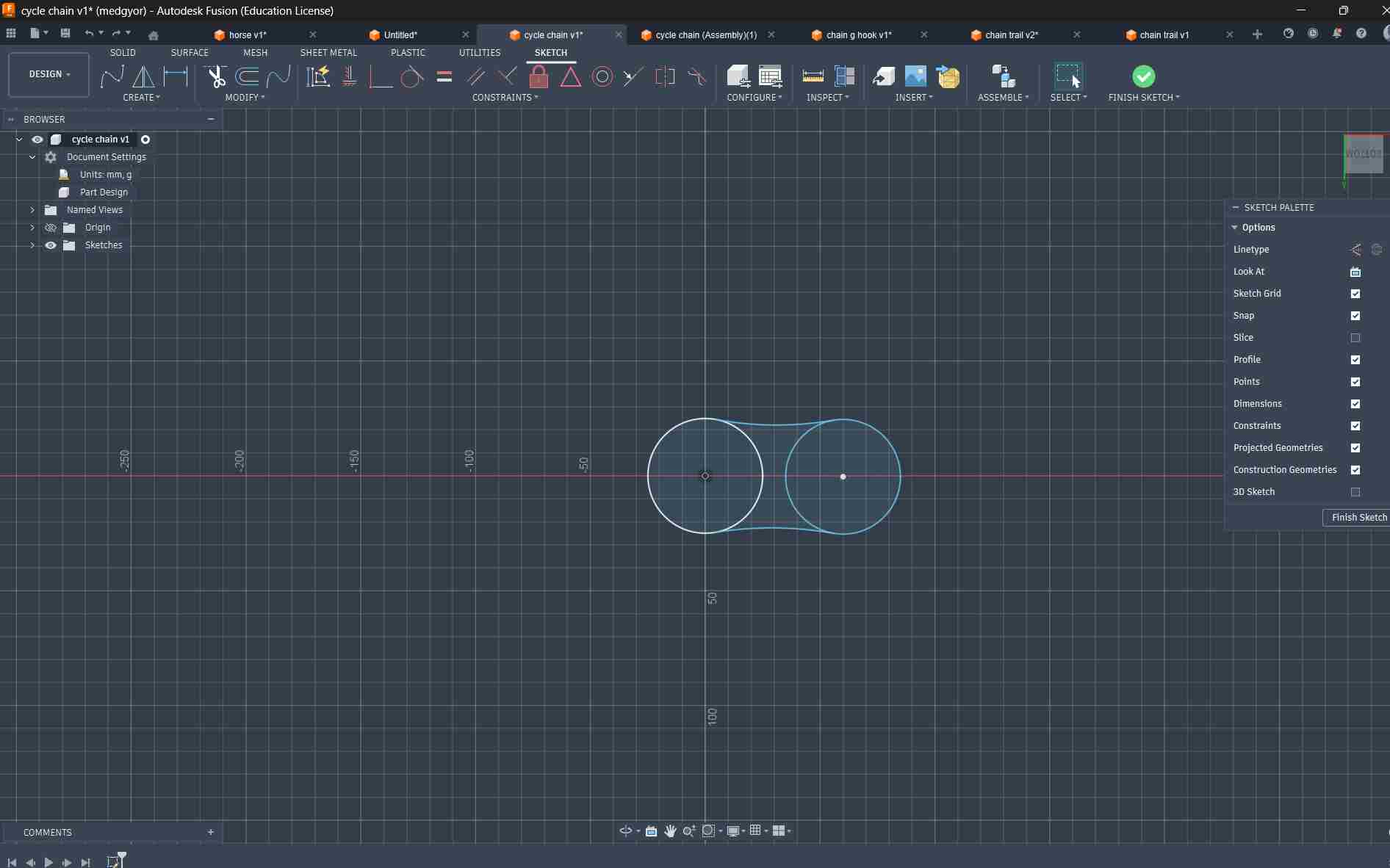
Design 2:motorcycle chain
Using the Center Circle tool, I created two circles and added two arcs between them using tangent constraints.
After that, I duplicated the design. In one model, I created two cylinders, and in the other, I created two holes in the same areas as in Design 1 and Week 02.
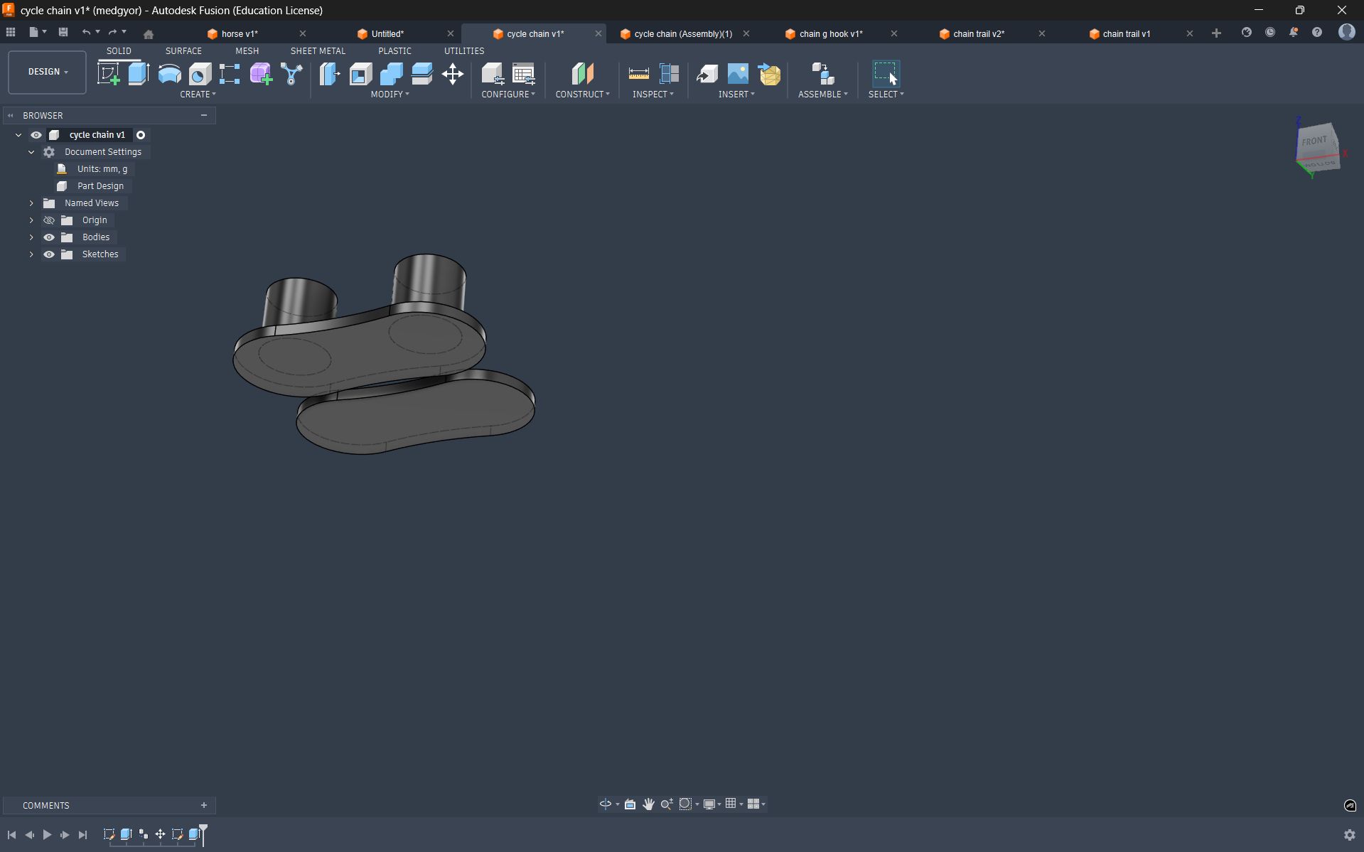
After that, I duplicated the design. In one model, I created two cylinders, and in the other, I created two holes in the same areas as in Design 1 and Week 02.
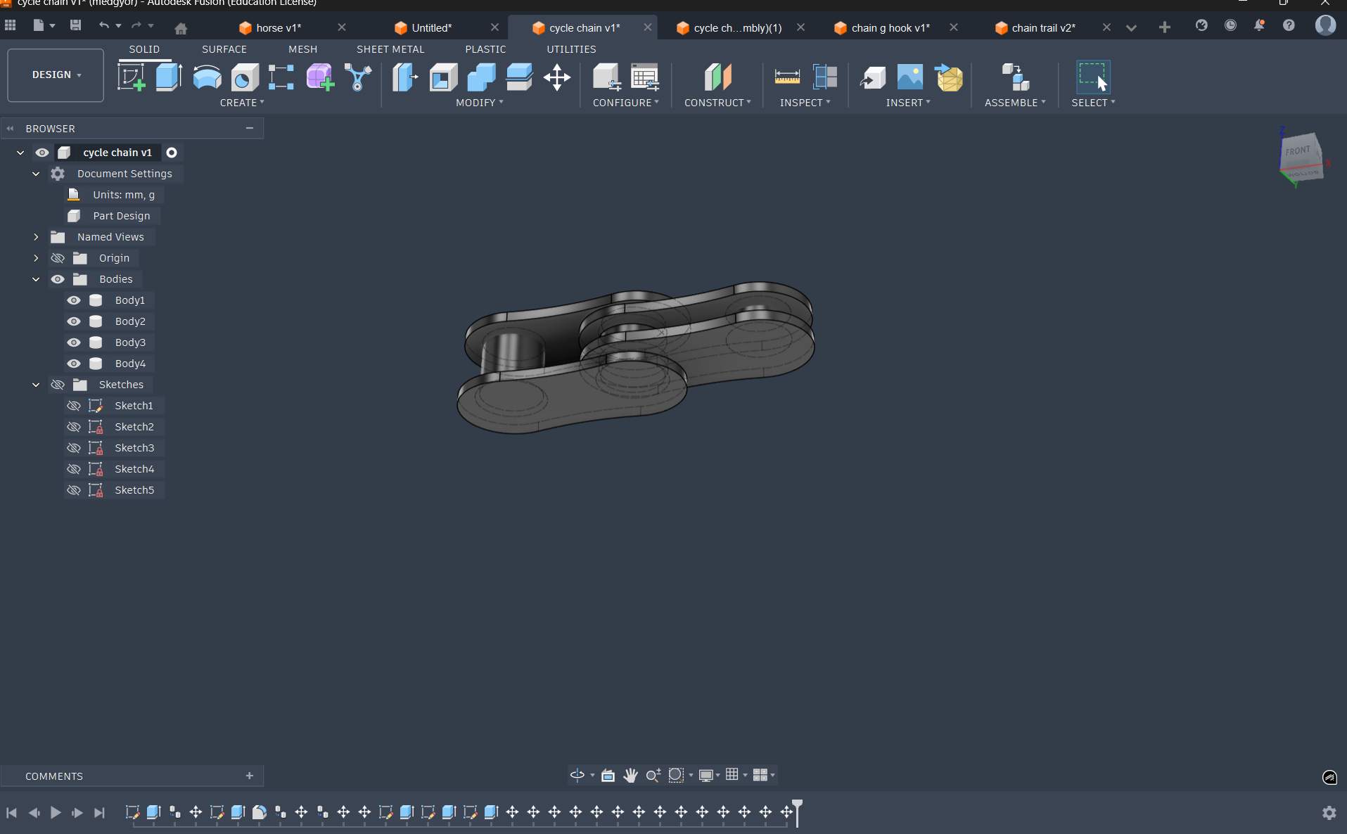
Using the Centre Circle tool, I created two concentric circles and extruded them to a thickness of 2 mm, then added two small pillars to connect the top plate and the next chain body for interlocking.
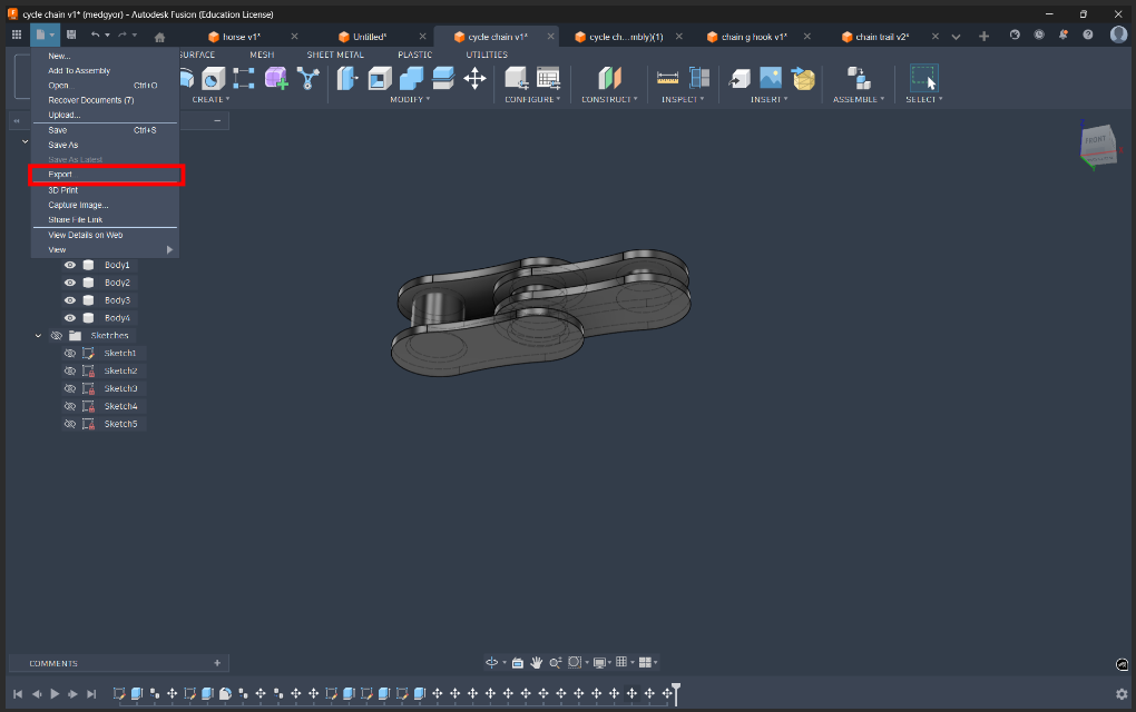
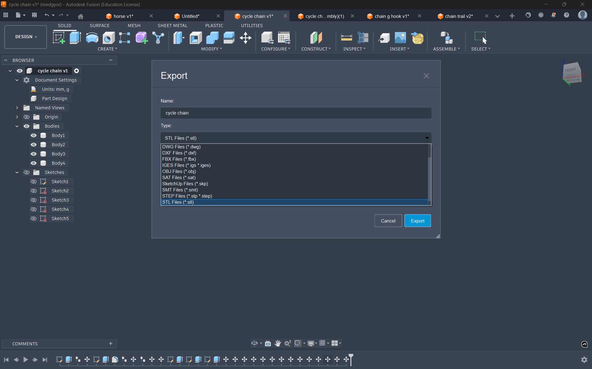
To export it as a STL file, go to File → Export, and from the available file format options, select STL.
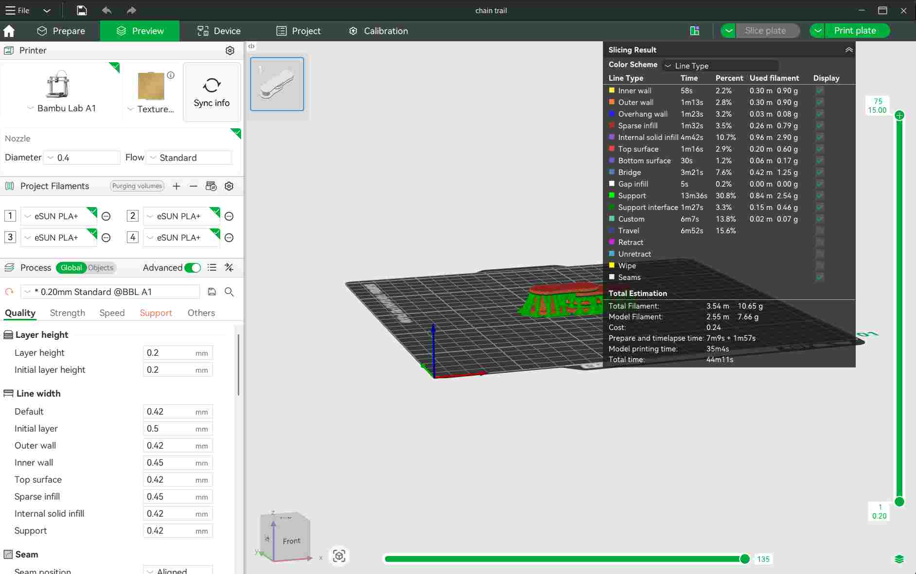
The support was selected as tree type and infill as 15%. Random seam was selected. Layer height was selected as 0.24mm
Filament Used
This week, I used eSUN White PLA filament for all my 3D printing assignments.
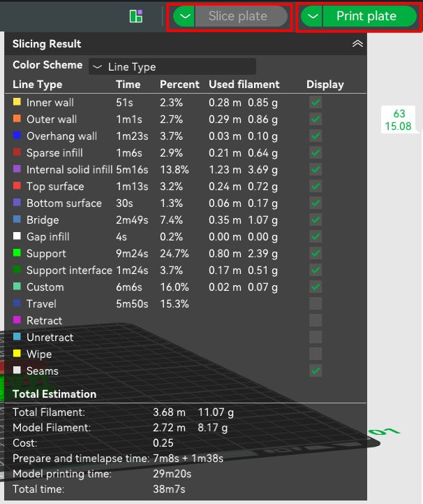
Slice the object
After making necessary changes, select print plate and select the printer in it. Select send. Then the job is fed to the printer
Then a window opens showing the printing page. The print status and camera feed can be seen on this page
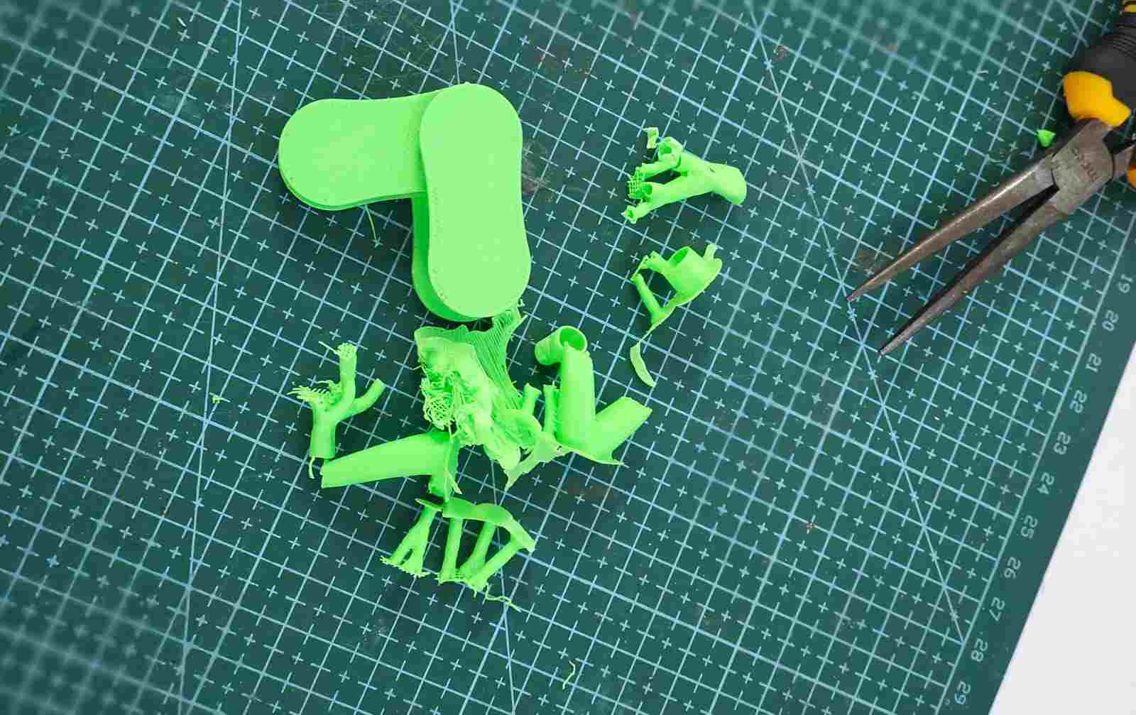
For post-processing of the motorcycle chain, I used a nose plier to remove the supports and a pen knife to clean the remaining material for a smooth finish.
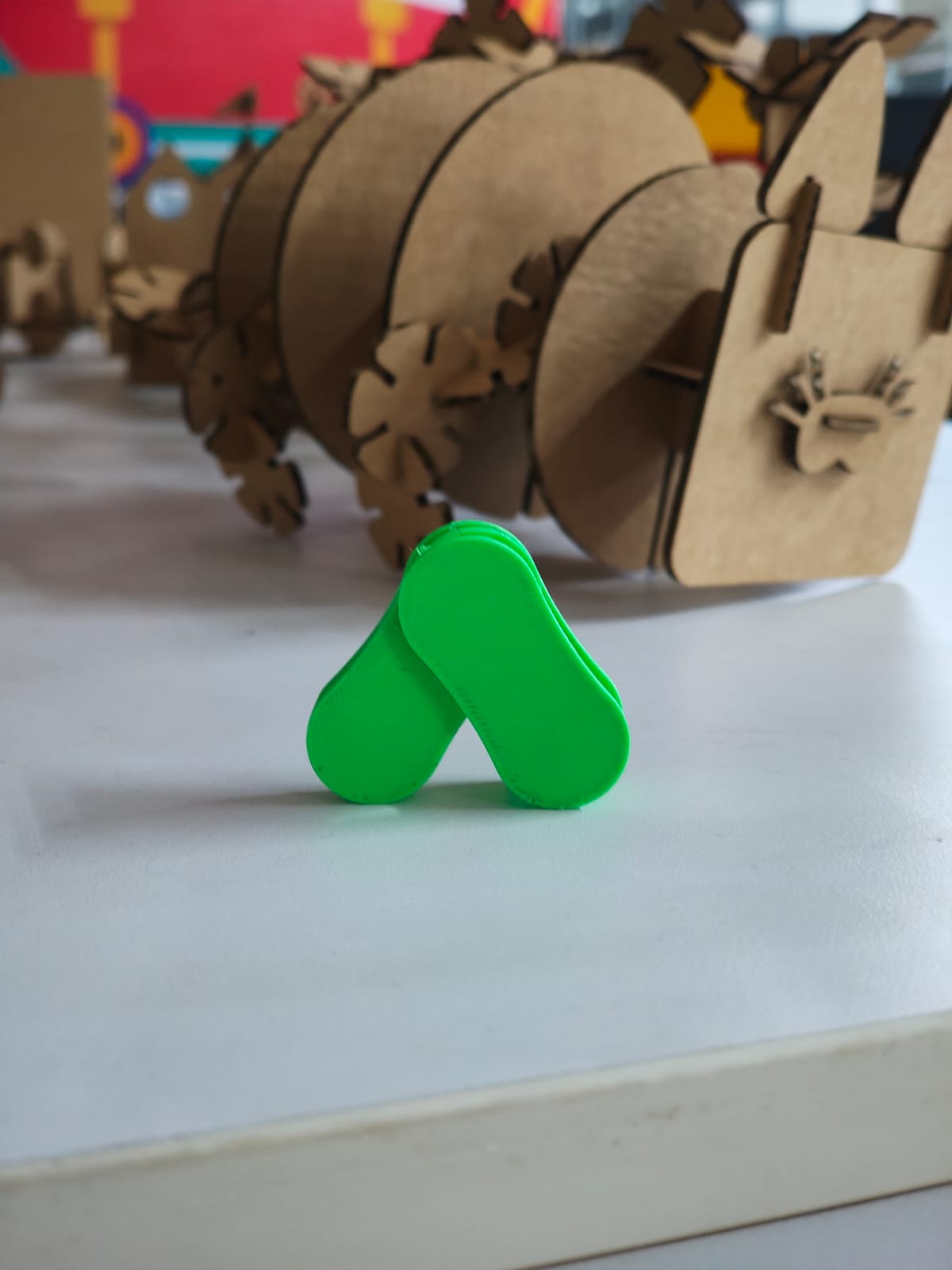
Hero Shot:02
Design 3:gravitational hook
For my third design, I attempted to print a gravitational hook. However, due to the long printing time and time constraints during the lab session, I was unable to complete the print.
If I get sufficient time in the future, I plan to print and test this design properly.
3D Scanning
3D scanning is a technology that captures the shape, size, and details of a physical object or environment to create a digital 3D model. It uses specialized scanners to collect data from multiple angles, which is then processed into an accurate virtual representation.
How it works?
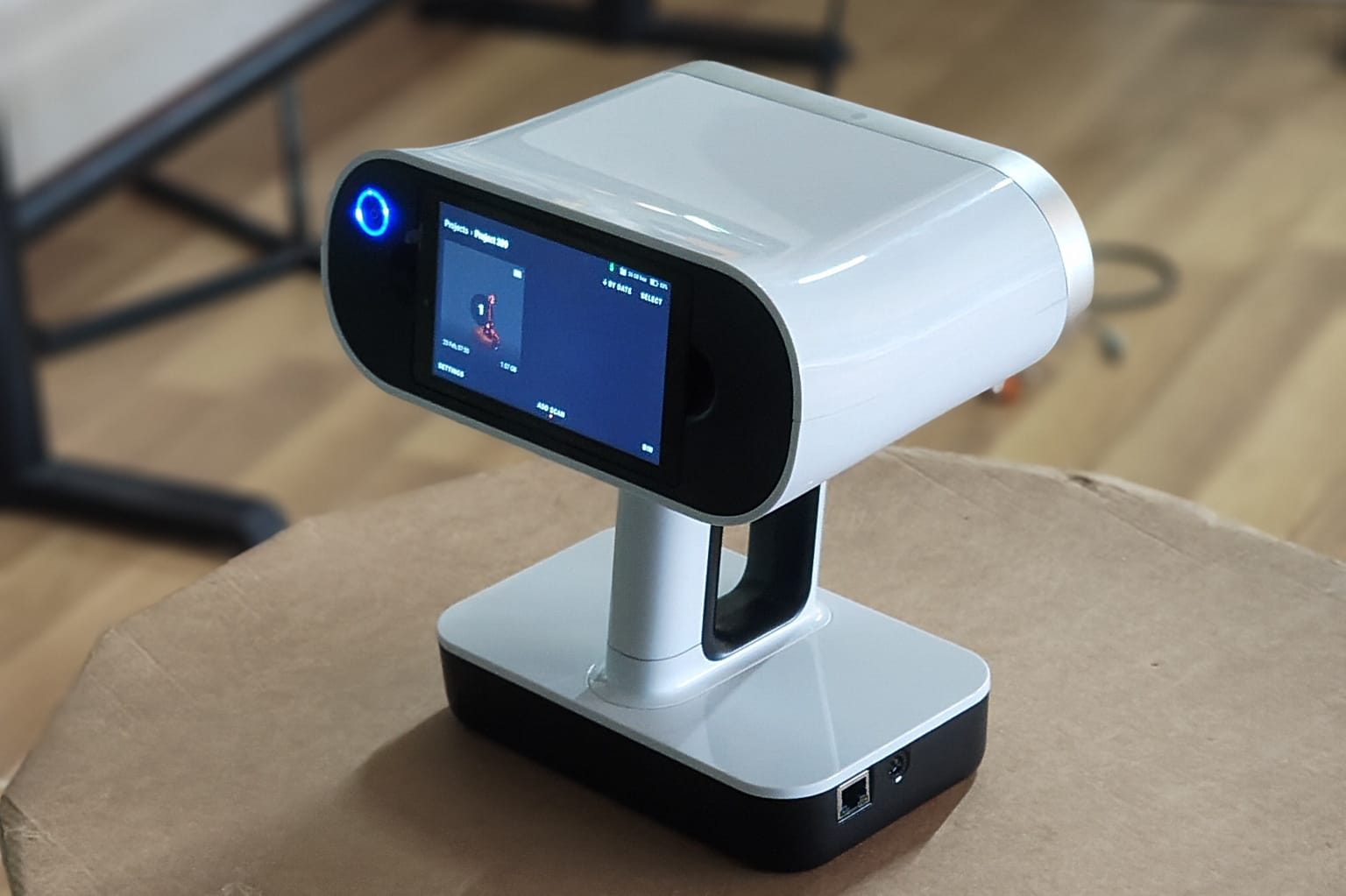
The Artec Leo. is a professional handheld 3D color scanner with automatic onboard processing and a touchscreen display for real-time model visualization. With an upgraded NVIDIA Jetson TX2 processor, it delivers faster processing speeds, enabling high-quality, real-time 3D data capture.
Artec Leo Scanner – Technical Specifications
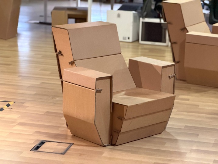
For this assignment, I scanned a cardboard sofa model.
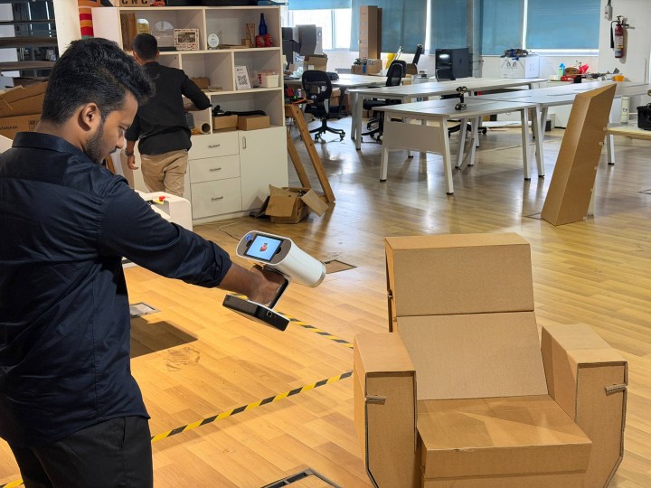
Here I am scanning the sofa using an Artec Leo. scanner.
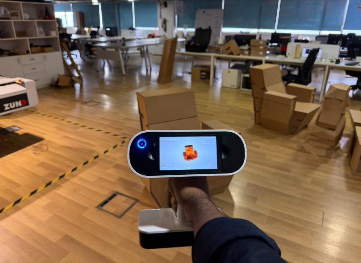
This is the scanned version of the sofa, shown as the raw output from the Artec Leo. scanner before processing. The model has not yet been aligned or cleaned in Artec Studio.
Postprocessing
The scan is transferred to Artec Studio 15 software.
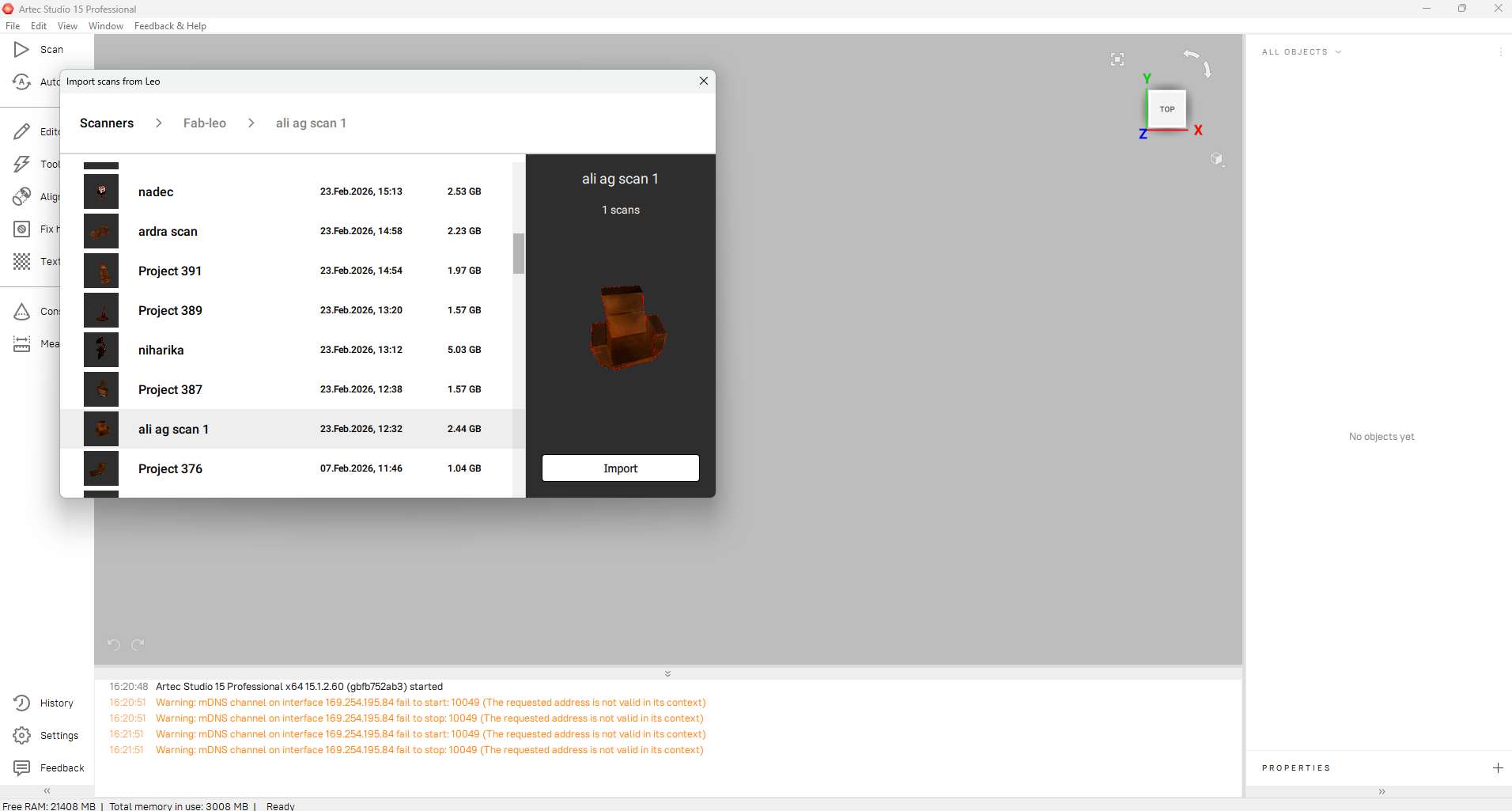
1. Importing the Raw Data
First, I connected my scanner and navigated to the Import menu. I located my project, "ali ag scan 1", which was about 2.44 GB. I clicked Import to bring the raw frames from the Artec Leo into my workspace.
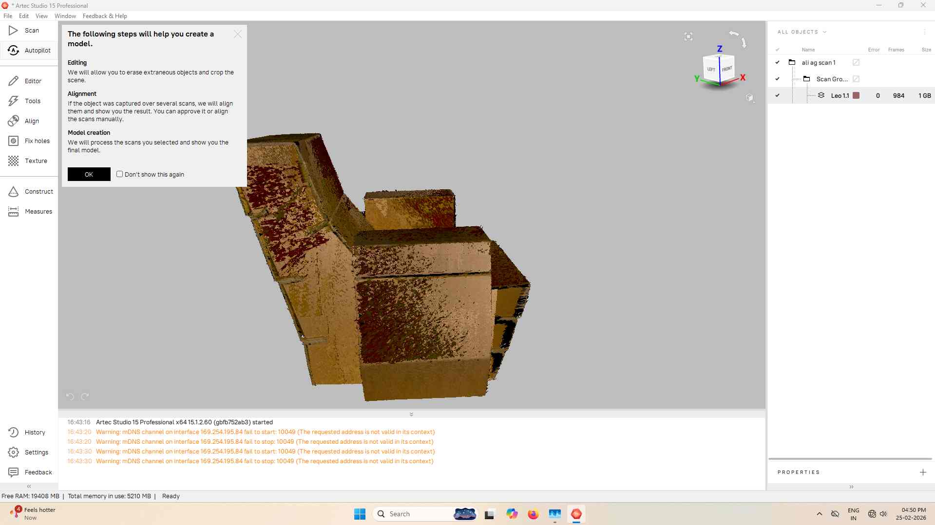
2. Launching Autopilot
Because I wanted an efficient path to a finished model, I initiated the Autopilot mode. I followed the on-screen prompts, which helped the software understand the object type and the desired output quality. This automatically prepared steps like Global Registration and Outlier Removal.
3. Cleaning the Workspace (Eraser Tool)
Before the final fusion, I removed the floor and unwanted scan noise.
- Opened the Editor tab and selected the Eraser.
- Used Rectangular selection and 2D selection to highlight unwanted areas.
- Enabled Select through to remove hidden artifacts behind the model.
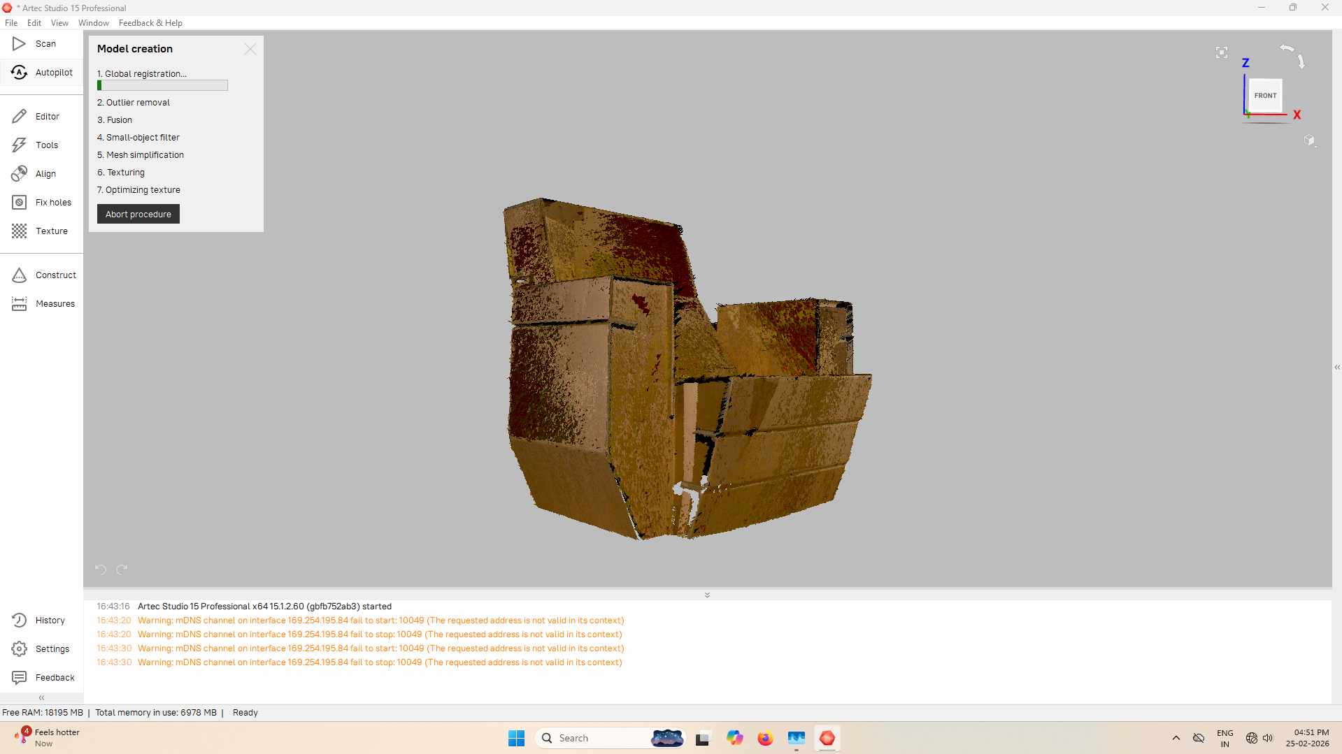
4. Running the Fusion
After cleaning the data, I ran the Sharp Fusion algorithm. Since the object had well-defined edges and flat planes, Sharp Fusion was ideal. The process took approximately 192 seconds to generate the solid mesh.
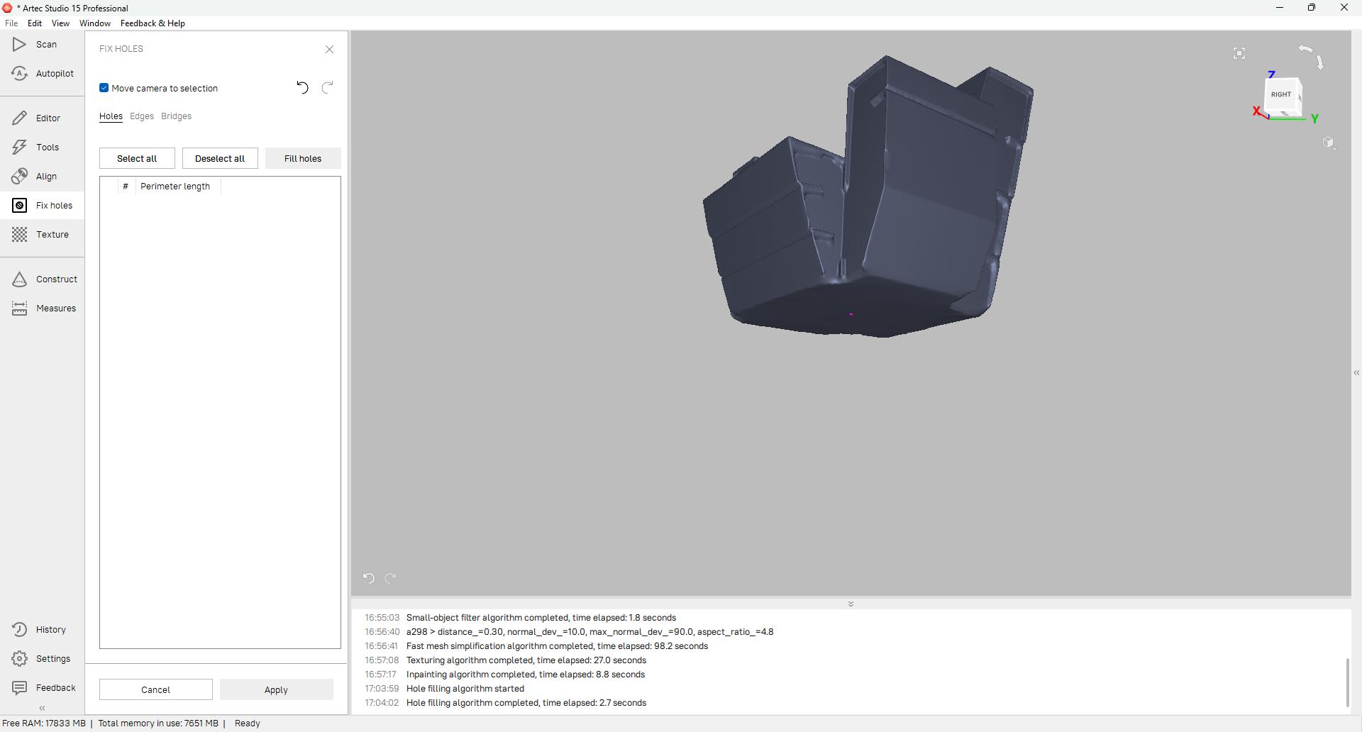
5. Repairing the Geometry
I used the Fix Holes tool to make the mesh watertight.
- Inspected tight corners for gaps.
- Used Fill holes to close open areas.
- Ensured the model was ready for STL export.
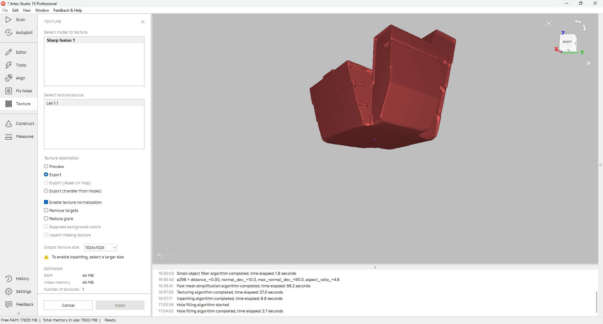
6. Applying Textures
To replicate the real cardboard appearance:
- Selected "Sharp fusion 1" as the destination mesh.
- Selected "Leo 1.1" frames as the source.
- Enabled Texture normalization to balance lighting.
- Clicked Apply to project color data onto the mesh.
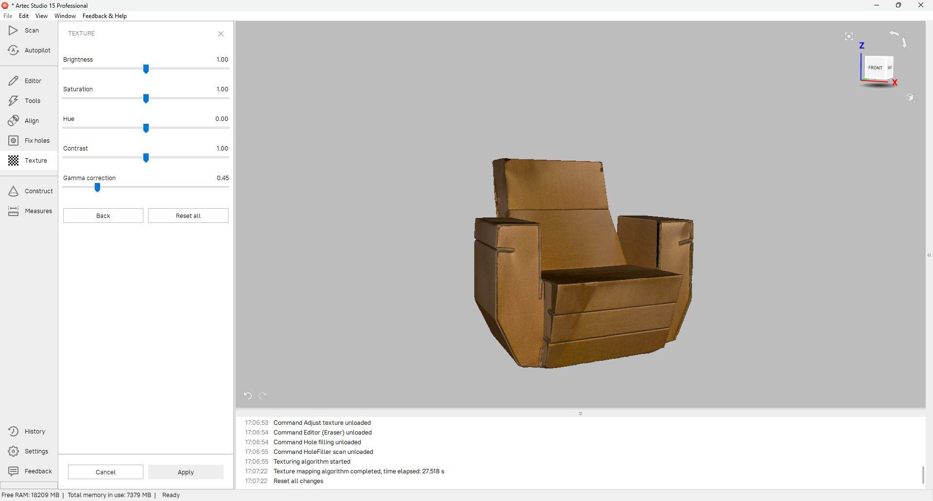
7. Visual Fine-Tuning
The texture appeared slightly dark, so I refined it using the Adjust Texture panel.
- Brightness: 1.00
- Saturation: 1.00
- Gamma Correction: 0.45
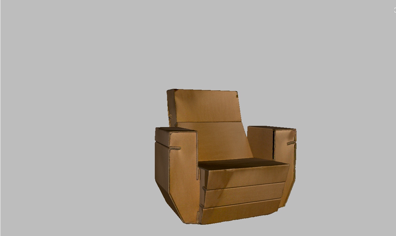
8. Final Export
Finally, I navigated to File > Export Mesh and saved the model as .STL. This format is ideal for 3D printing and CAD applications.
HeroShot:03
Conclusion
This week I learned about 3D scanning and printing. In group assignment we explored about 3D printing, its types, safety measures and test rules. 3D models were made in fusion 360 and printed in Bambu Lab A1 printer. Learned about 3D scanning process and scanned an object.
References
Software & Tools
- Bambu Studio - 3D printing slicer software
- Fusion 360 - 3D CAD/CAM software by Autodesk
- Artec Studio - 3D scanning software
Hardware & Equipment
- Bambu Lab A1 - 3D printer used in this assignment
- Artec Leo - 3D scanner
Resources & Tutorials
- 3D Printing Workflow - Process explanation
- Group Assignment - 3D printer design rules testing
- Additive vs Subtractive Manufacturing - Comparison image
Download Files
- Chain Keychain (F3D) - Fusion 360 design file
- Cycle Chain (F3D) - Fusion 360 design file