Week 04 Embedded Programming
Objectives
Group assignment
Individual Assignment
Group Assignment: Toolchain & LED Blink Comparison
This comparison focuses specifically on toolchain setup and LED blink implementation across four microcontroller platforms. The evaluation is based only on practical experience with development environment configuration and basic GPIO blinking.
| Board | Development Environment | Programming Level | Build Process | Flashing Method | Blink Implementation Style | Observed Complexity |
|---|---|---|---|---|---|---|
| Arduino Q (UNO R4 WiFi) | Arduino IDE / Arduino Cloud | High-level C++ | Automatic compile & upload | USB (One-click) | digitalWrite() | Very Easy |
| ESP32-C6 | VS Code + ESP-IDF | C / Assembly (RISC-V) | idf.py build (manual build system) | idf.py flash | Direct GPIO register control | High |
| ESP32-S3-DEV-KIT | VS Code + PlatformIO | C++ (Arduino Framework) | PlatformIO build system | USB via PlatformIO | digitalWrite() / NeoPixel library | Medium |
| ATtiny44/84 | Microchip Studio + AVR-GCC | Embedded C | Compile → Generate HEX | AVRDUDE + ISP Programmer | Direct PORT register manipulation | Medium (Low-level) |
this table is taken from Group Group Assignment page
Summary Observations
Conclusion
The comparison highlights how toolchain structure and abstraction level vary significantly between platforms. While all four boards successfully executed a basic LED blink program, the setup complexity, build process, and programming depth differed substantially. This demonstrates how architecture and ecosystem design directly influence the embedded development experience.
Click here to view the group documentation of Group Assignment
Exploring Xiao Rp2040
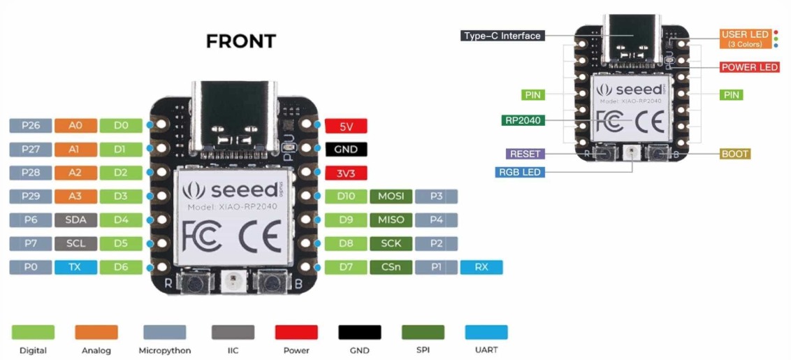 Image source
.
Image source
.
Board Overview
The XIAO RP2040 is a compact development board made by Seeed Studio. It is built around the RP2040 microcontroller chip. The board is roughly thumb-sized and is designed to be breadboard-friendly.
Physical Connections
At the top of the board is a USB Type-C interface, which is used for both powering the board and uploading programs from a computer.
Along the two sides of the board are 14 pins in total. Each pin can serve multiple functions depending on how you configure it in your program:
- D0-D10 (green) are digital pins, used for general input and output. This is what I used for my LEDs and button.
- A0-A3 (orange) are analog pins, used for reading variable voltage values like from a sensor or potentiometer. These share the same physical pins as D0-D3.
- SDA (D4) and SCL (D5) are used for I2C communication with other devices.
- TX (D6) and RX (D7) are used for UART serial communication.
- MOSI (D10), MISO (D9), SCK (D8), CSn (D7) are used for SPI communication.
- 5V and 3V3 are power output pins.
- GND is ground.
What I found important to understand is that most pins are multi-function. The same physical pin can act as digital, analog, or a communication pin depending on what your program tells it to do.
Onboard Components
Looking at the back of the board diagram, there are several built-in components that do not need any external wiring:
- RGB LED (User LED, 3 colors) is a programmable LED built into the board. One thing that caught me off guard is that on the XIAO RP2040, this LED is inverted, meaning you write LOW to turn it on and HIGH to turn it off, which is the opposite of what you would expect.
- Power LED lights up whenever the board is receiving power.
- RESET button (R) restarts the program running on the board.
- BOOT button (B) is used when flashing new firmware. Holding it while connecting USB puts the board into bootloader mode.
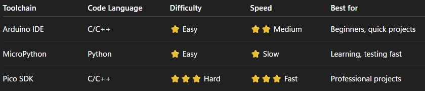
I went through the RP2040 Datasheet that provides a detailed understanding of the microcontroller
Data sheet of RP2040.
The chip name is based on the following naming convention:
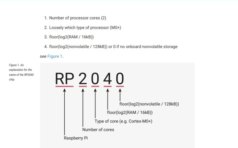
Data sheet of RP2040.
The following diagram represents the system architecture of the RP2040 microcontroller.
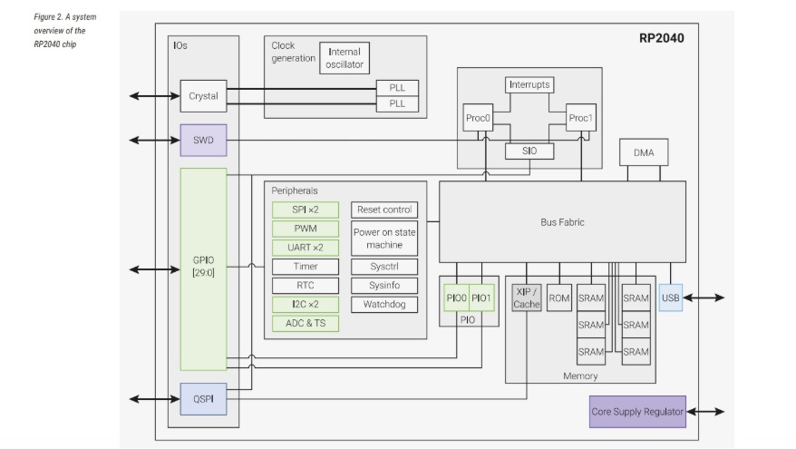
Data sheet of RP2040.
Some of the key features of the RP2040 include:
- Dual ARM Cortex-M0+ processor cores, up to 133 MHz
- 264 KB of on-chip SRAM, organized into 6 banks
- 30 multifunction GPIO pins
- 6 dedicated I/O pins for SPI Flash (supports XIP – Execute In Place)
- Dedicated hardware support for commonly used peripherals
- Programmable I/O (PIO) for extended peripheral support
- 4-channel ADC with internal temperature sensor, 500 ksps, 12-bit conversion
- USB 1.1 Host/Device support
Data sheet of RP2040.
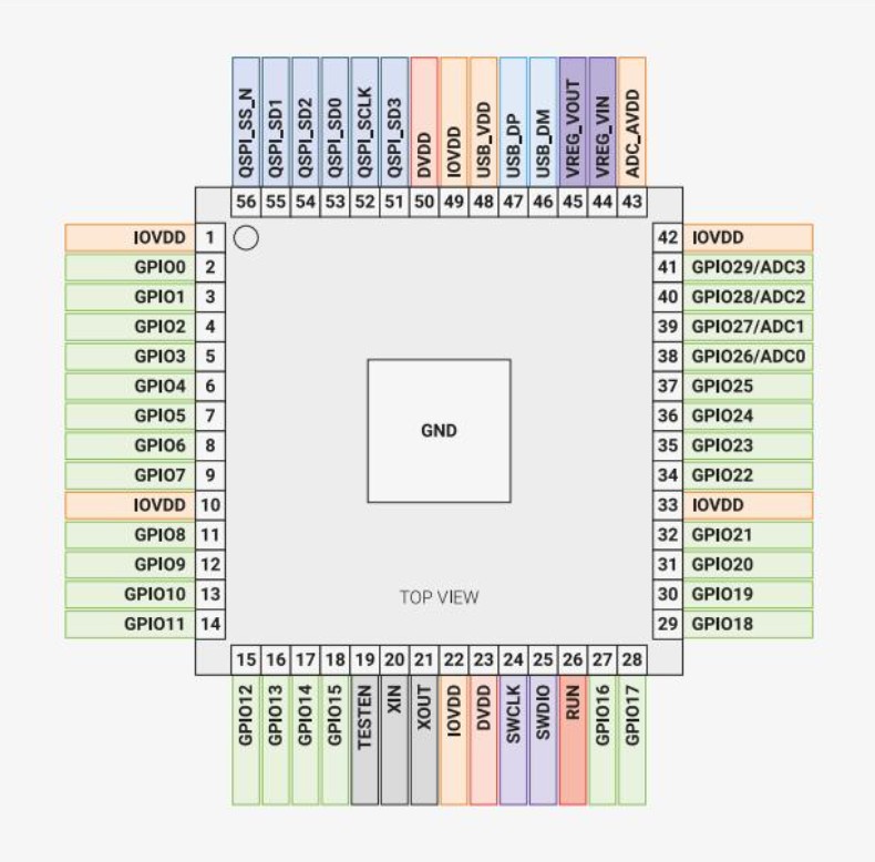
Pin Out diagram
A "pinout diagram" is a diagram or list that shows the arrangement and function of the pins (or terminals) on an electronic component or connector, helping users understand how to connect and interact with the device. Shown below is the pinout diagram of a xiao rp2040 microcontroller.
Data sheet of RP2040.
Each individual GPIO pin can be connected to an internal peripheral through the GPIO functions defined below. Some internal peripheral connections are available in multiple locations, providing system-level flexibility. The SIO, PIO0, and PIO1 blocks can be connected to all GPIO pins and are controlled by software (or software-controlled state machines). Therefore, they can be used to implement a wide range of functions.
Understanding Arduino IDE and Micropython
Micropython
MicroPython is a lightweight version of Python designed for microcontrollers, while the Arduino IDE is a platform used for writing and uploading code to microcontroller boards, typically using C/C++. Both allow easy interaction with hardware through GPIO pins, sensors, and actuators.
Arduino IDE
It is a software environment for programming Arduino microcontroller boards. Arduino IDE provides an easy-to-use interface for writing, compiling, and uploading code to the board. It is widely used in hobbyist, DIY, and educational projects for electronics and robotics. It includes very helpful libraries and built-in functions to get started with a program and simplifies hardware interaction.
Programming
This week, I experimented with programming a microcontroller using both the Arduino IDE (C/C++) and Thonny (MicroPython).
To understand how programming works, we began by writing a simple LED blinking program.
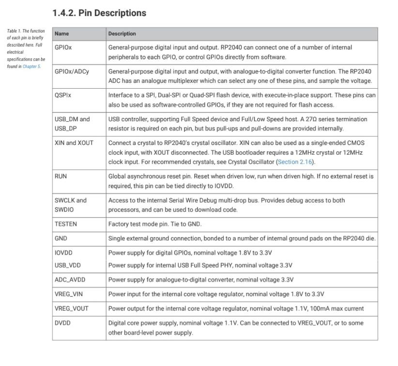
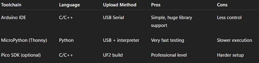
Toolchain Comparison
AI Image Prompt
Prompt: "toolchain comparison between arduino microphython pico sdk in a simple way understanding 10year old child"
AI Tool Used: ChatGPT
- Arduino IDE is best for beginners because it has many libraries and examples.
- MicroPython is best for quick testing because you can run code fast without compiling.
- Pico SDK is best for professional projects because it gives full control and maximum performance.
Trying out Arduino IDE
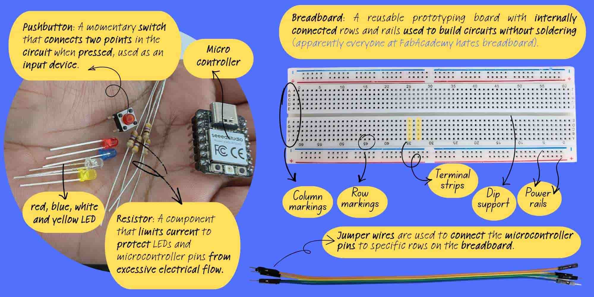
- Microcontroller (Seeed Studio XIAO Board): Acts as the brain of the circuit, executing the program and controlling inputs and outputs.
- Push Button: A momentary switch that sends an input signal to the microcontroller when pressed.
- LEDs (Red, Blue, White, Yellow): Output devices that emit light and indicate different states or signals.
- Resistors: Limit current flow to protect LEDs and microcontroller pins from excessive current.
- Power Rails: Long rows on the breadboard used to distribute power (VCC) and ground (GND).
- Terminal Strips: The main breadboard area where components are connected; holes in the same row are electrically connected.
- Column Markings: Letter labels (A–J) used to identify breadboard positions.
- Row Markings: Number labels used to identify breadboard positions.
- Center Gap (DIP Support): The middle gap that allows integrated circuits (ICs) to be placed across the breadboard.
- Jumper Wires: Used to create temporary connections between the microcontroller and breadboard without soldering.
Hardware Setup
I tested the code using the Seeed Studio XIAO RP2040 with the following components:
- xiao RP2040
- LED
- Resistor (220Ω)
- Push button
- Breadboard
- Jumper wires
- PC (Arduino IDE)
- The resistor value was selected using the resistor colour code. Resistor Code.
- Why a Resistor is Needed: LEDs do not have internal resistance to limit current. So, if an LED is connected directly to a 5V supply, it may draw too much current and burn out.
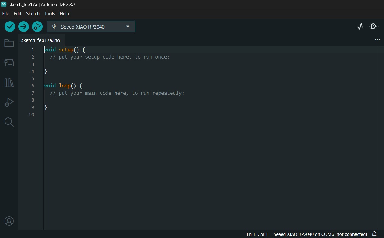
- Step 1: IDE Installation: I installed the latest version of the Arduino IDE .
-
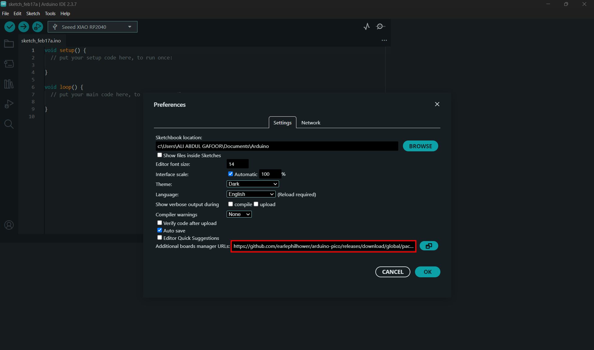
Step 2: Adding Board Support:
I navigated to File > Preferences and added the following URL to the
Additional Boards Manager URLs field:
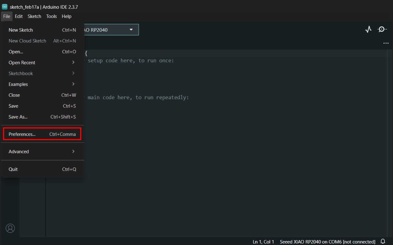
Entered the following URL in Additional Boards Manager URLs
https://github.com/earlephilhower/arduino-pico/releases/download/global/package_rp2040_index.json
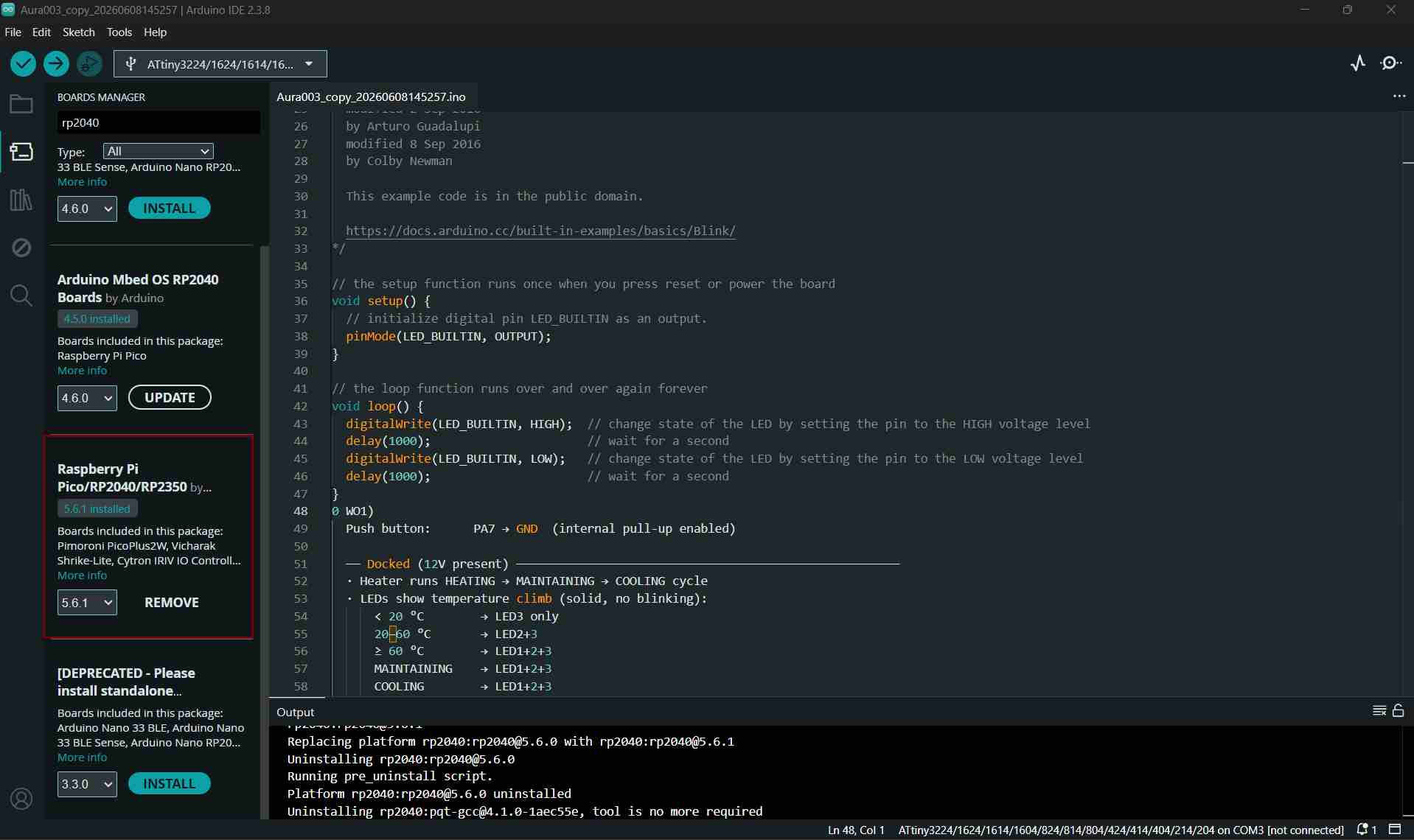
- Step 3: Core Installation: I opened Tools > Board > Boards Manager, searched for RP2040, and installed the Raspberry Pi Pico/RP2040 package.
- Step 4: BOARD - I navigated to Tools → Board → Raspberry Pi RP2040/RP2350 → Seeed XIAO RP2040 and selected the correct board for my microcontroller.
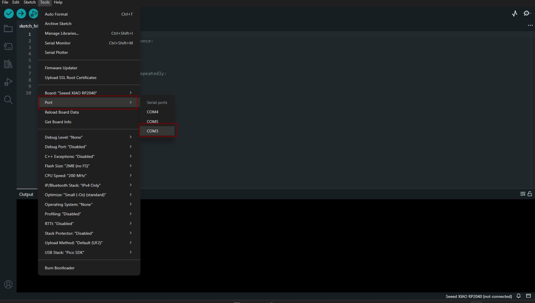
- Step 5: PORT - I navigated to Tools > Port and selected the serial port name of the connected Seeed Studio XIAO RP2040. This was likely to be COM3 or higher. This is where we have connecetd our RP2040
 >
>
Experiment 01: Blink Program from Library
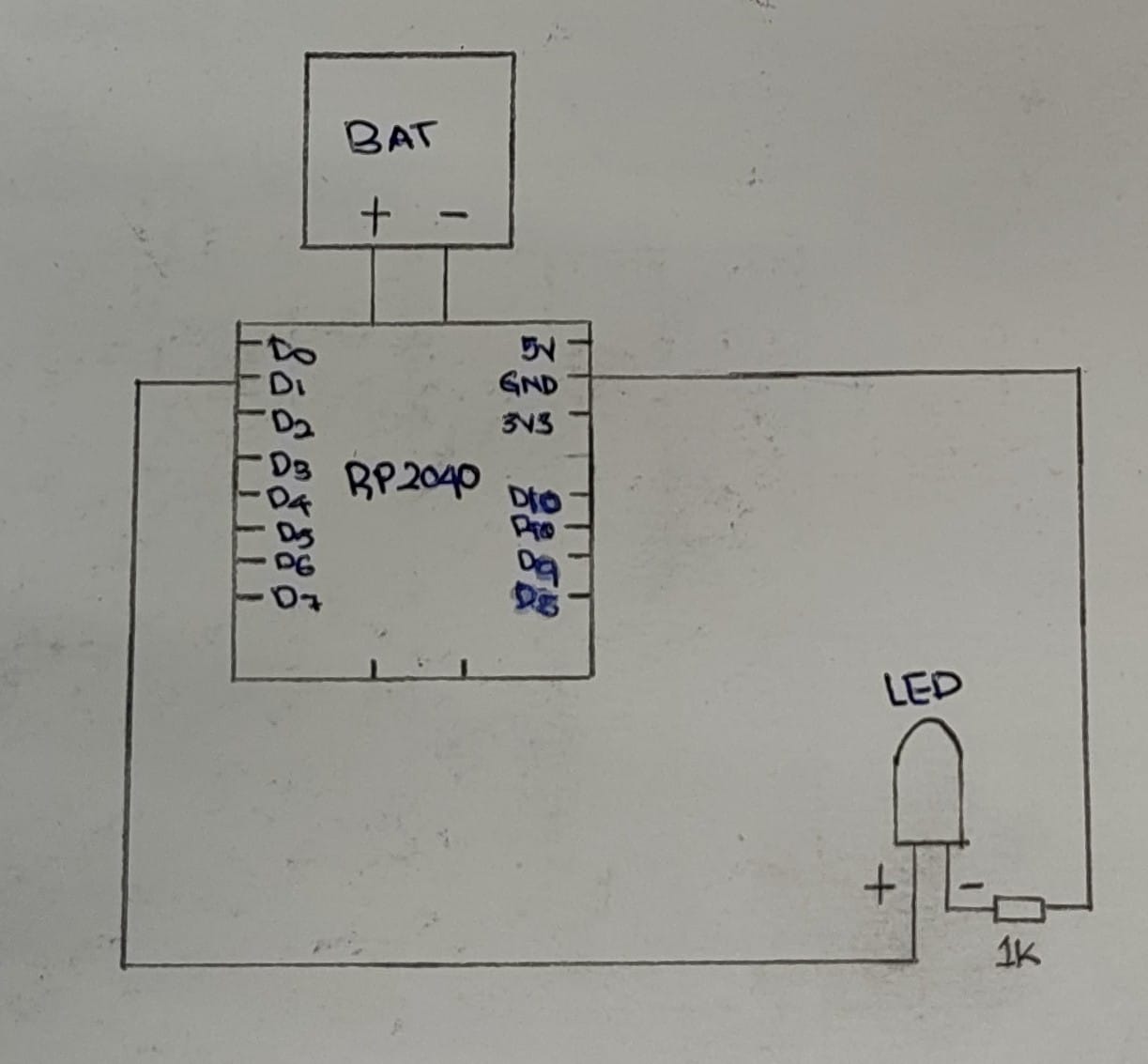
I used a Seeed Studio XIAO RP2040 board and connected an external LED to it. I then used the built-in example code to blink the LED.
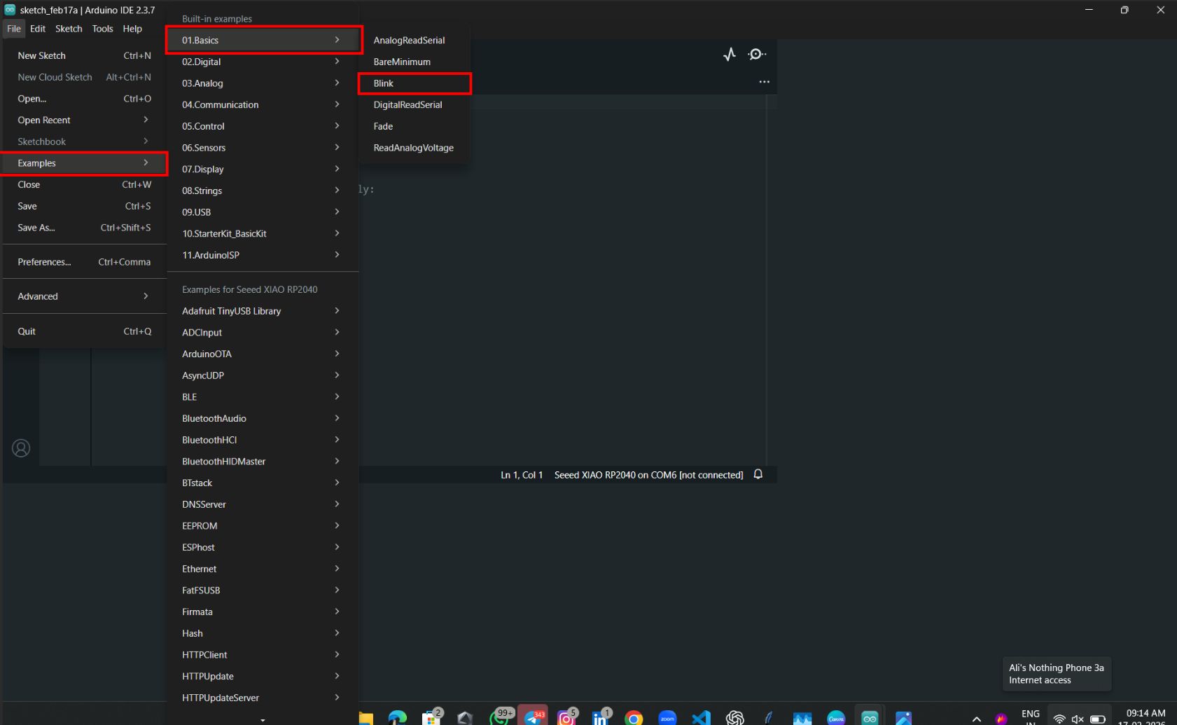
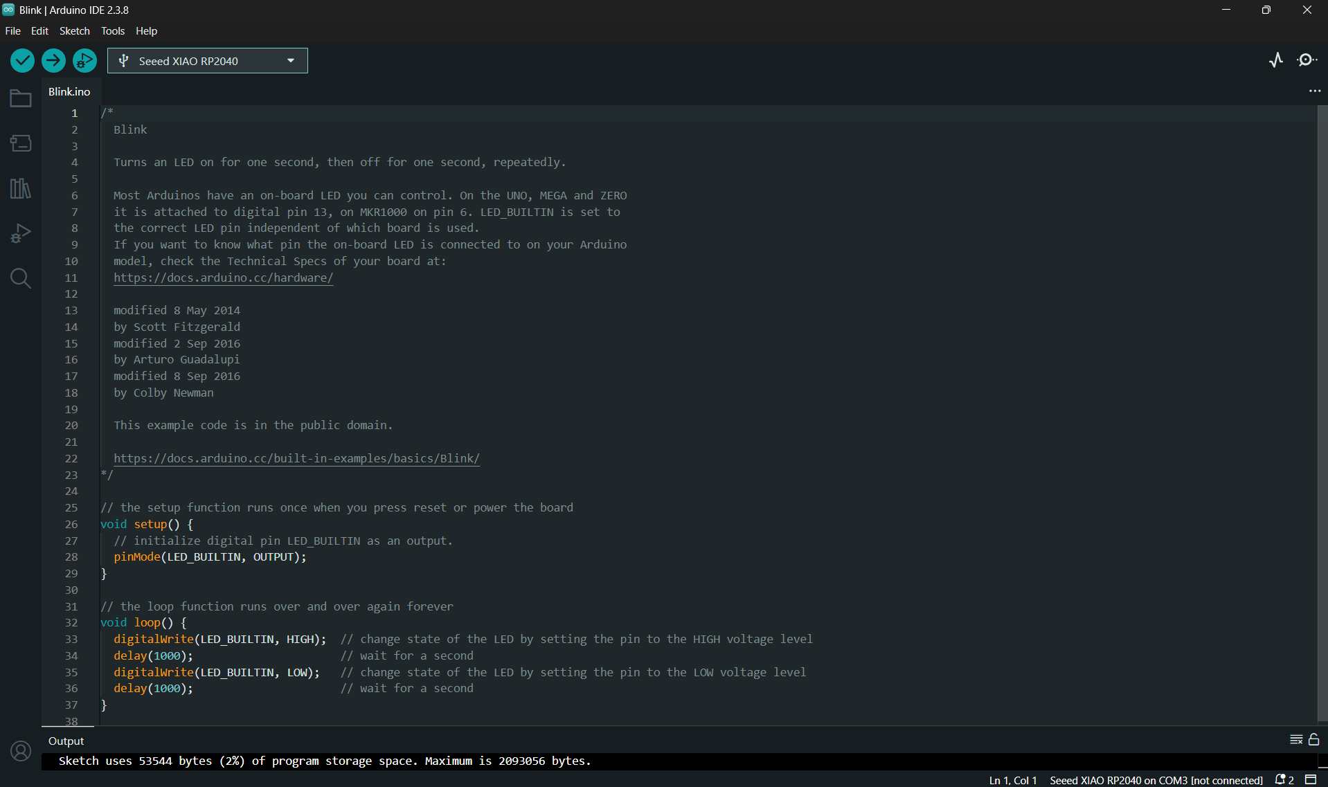
This is the example code
Board Pinout
- LED → D2
- Resistor value (1Ω)
- GND connections
Connection diagram
Code
/*
  Blink

  Turns an LED on for one second, then off for one second, repeatedly.

  Most Arduinos have an on-board LED you can control. On the UNO, MEGA and ZERO
  it is attached to digital pin 13, on MKR1000 on pin 6. LED_BUILTIN is set to
  the correct LED pin independent of which board is used.
  If you want to know what pin the on-board LED is connected to on your Arduino
  model, check the Technical Specs of your board at:
  https://docs.arduino.cc/hardware/

  modified 8 May 2014
  by Scott Fitzgerald
  modified 2 Sep 2016
  by Arturo Guadalupi
  modified 8 Sep 2016
  by Colby Newman

  This example code is in the public domain.

  https://docs.arduino.cc/built-in-examples/basics/Blink/
*/

// the setup function runs once when you press reset or power the board
void setup() {
  // initialize digital pin LED_BUILTIN as an output.
  pinMode(LED_BUILTIN, OUTPUT);
}

// the loop function runs over and over again forever
void loop() {
  digitalWrite(LED_BUILTIN, HIGH);  // turn the LED on (HIGH is the voltage level)
  delay(1000);                      // wait for a second
  digitalWrite(LED_BUILTIN, LOW);   // turn the LED off by making the voltage LOW
  delay(1000);                      // wait for a second
}
Code explained
LED_BUILTIN– The LED on the board.pinMode(LED_BUILTIN, OUTPUT);– Sets the LED pin as an OUTPUT.digitalWrite()– Defines the action to perform on the LED.digitalWrite(LED_BUILTIN, HIGH);– Turns the LED ON by setting the pin to HIGH.delay(1000);– Pauses the program for 1000 milliseconds (1 second) before executing the next instruction.
Changing the Delay Time
delay(1000);→ LED blinks every 1 second.delay(500);→ LED blinks twice as fast.delay(2000);→ LED blinks more slowly, once every 2 seconds.
Observation: As the delay time decreases, the LED blinks faster. As the delay time increases, the LED blinks slower.
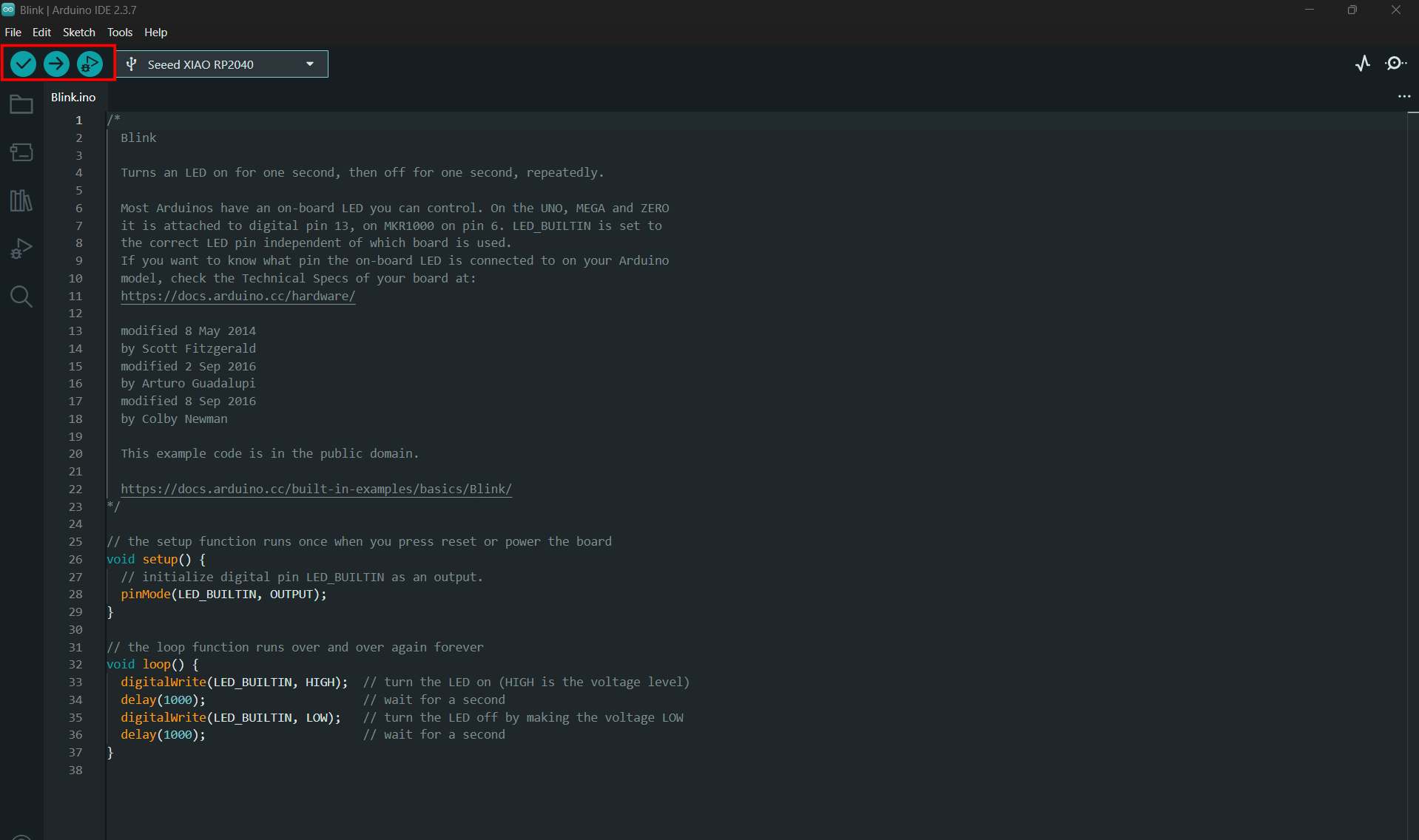
After writing the code, click the tick (✓) button to compile and verify the sketch. Once the compilation is successful, click the arrow (→) Upload button to upload the program to the board.
Experiment 02: Aeroplane Blink (RP2040)
This was my second trial using the RP2040, where I implemented an aeroplane-style LED blinking pattern.
#define LED_PIN 2

v#define LED_PIN 2   // LED is connected to pin 2

void setup() {
  pinMode(LED_PIN, OUTPUT);  // Tell Arduino that LED_PIN is for the LED
}

void loop() {

  // Turn the LED ON
  digitalWrite(LED_PIN, HIGH);
  delay(100);  // Wait a tiny bit

  // Turn the LED OFF
  digitalWrite(LED_PIN, LOW);
  delay(100);  // Wait a tiny bit

  // Turn the LED ON again
  digitalWrite(LED_PIN, HIGH);
  delay(100);  // Wait a tiny bit

  // Turn the LED OFF again
  digitalWrite(LED_PIN, LOW);

  // Wait longer before doing the blink again
  delay(700);
}
AI Image Prompt
Prompt: " i have Rp2040 I need to blink led like aeroplane i connected led in to d2
AI Tool Used: ChatGPT
The aeroplane blink output was very satisfying and relaxing to watch. I also experimented by changing the delay values to adjust the blinking speed and pattern.
Experiment 03 – LED Chaser (RP2040)
This was my third trial on the RP2040. In this experiment, I programmed five LEDs to blink continuously in a sequence, similar to party lights.
int leds[] = {2, 3, 4, 5, 6};  // LEDs are connected to pins 2, 3, 4, 5, and 6

void setup() {
  // Set all LED pins as outputs
  for (int i = 0; i < 5; i++) {
    pinMode(leds[i], OUTPUT);
  }
}

void loop() {
  // Turn on one LED at a time
  for (int i = 0; i < 5; i++) {
    digitalWrite(leds[i], HIGH);  // Turn the LED ON
    delay(150);                   // Wait a little bit
    digitalWrite(leds[i], LOW);   // Turn the LED OFF
  }
}
AI Image Prompt
Prompt: " i have 5 led white green blue red yellow i need blink like chaser.White → D0.using rp2040
Green → D1
Blue → D2
Red → D3
Yellow → D4"
AI Tool Used: ChatGPT
Experiment 04:OLED Display Output Test
Components Required
Main Parts
- Seeed Studio XIAO RP2040
- OLED Display (I2C) (Usually 0.96 inch SSD1306, 128×64)
Connection Items
- Jumper wires (4 wires)
- USB Type-C cable (to power + upload code)
- Breadboard (if you want neat wiring)
Connection diagram
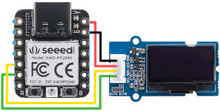 Seeed Studio.
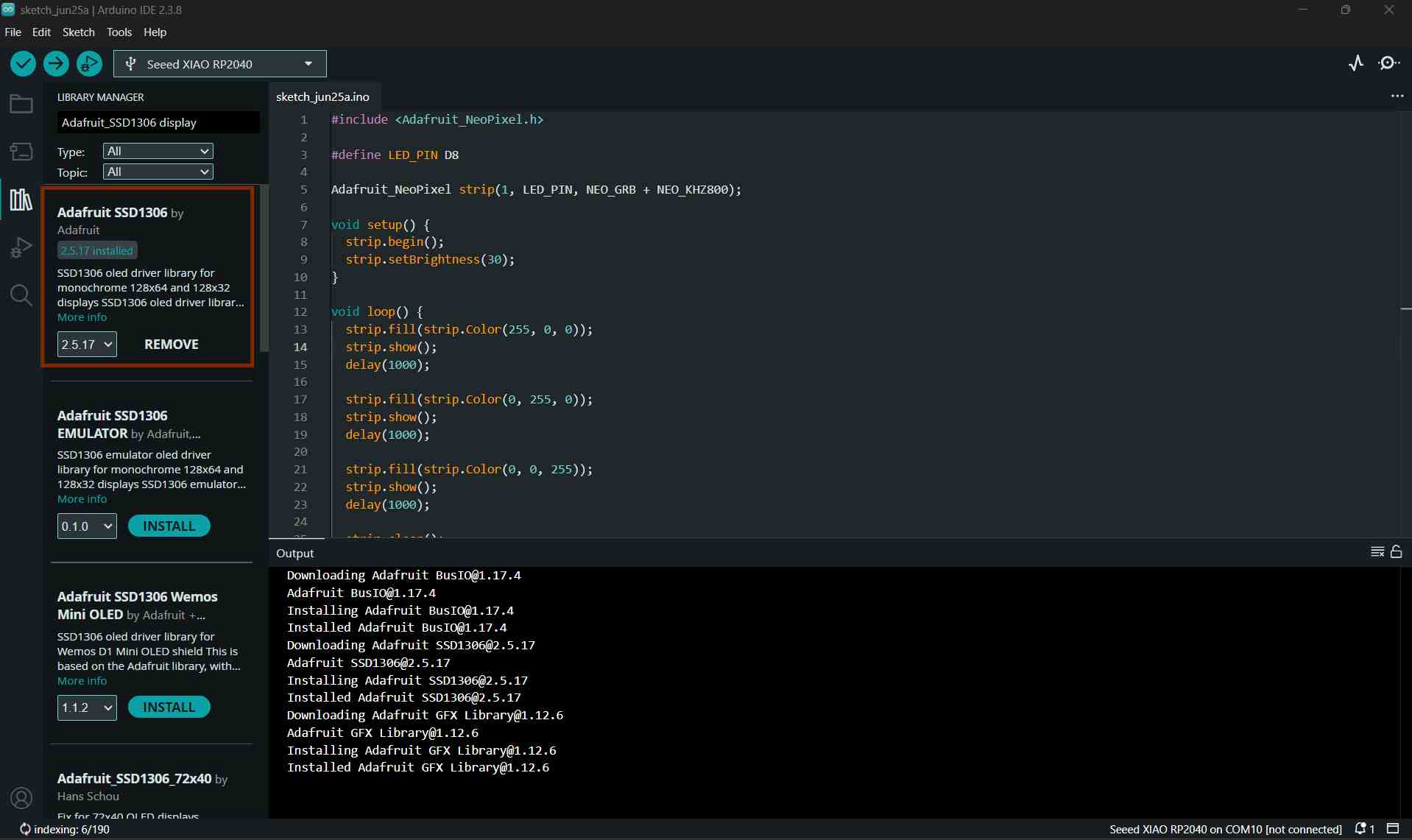
Library Installing
To interface with the OLED display, I installed the Adafruit SSD1306 library in the Arduino IDE.
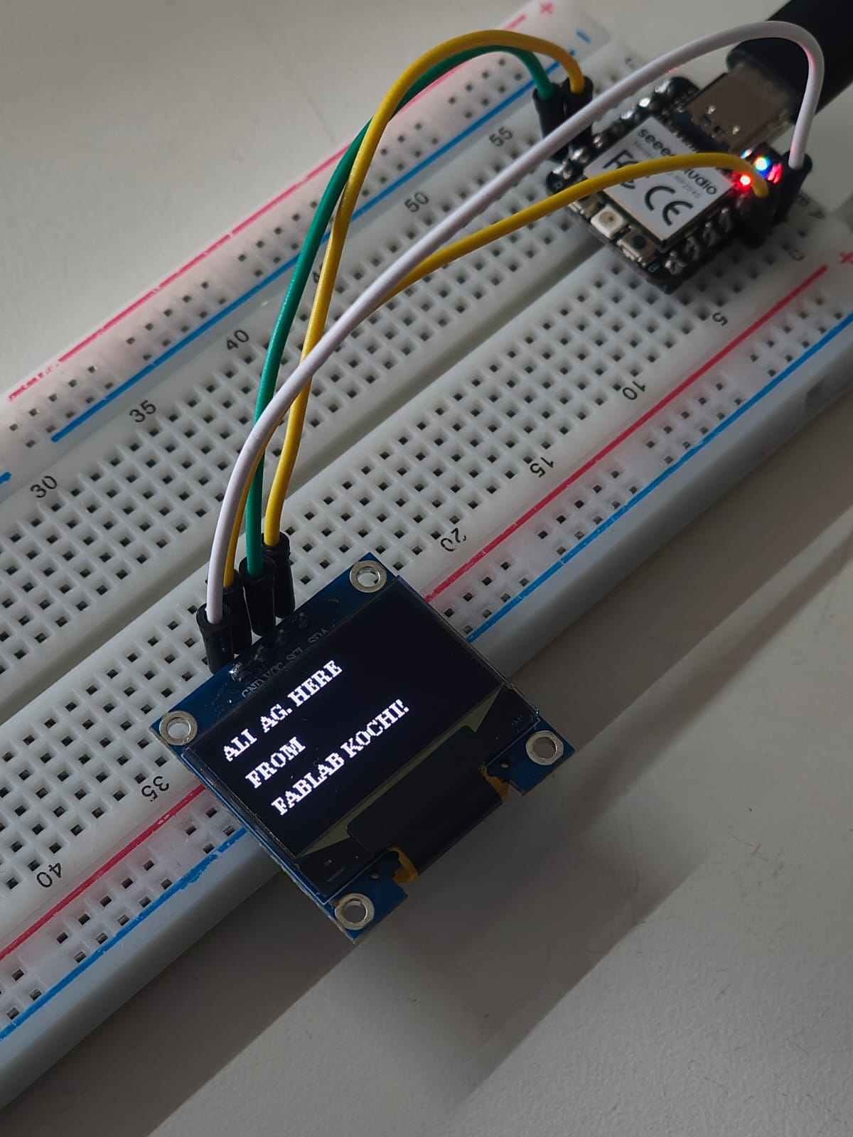
In this experiment, I tested an OLED display using the RP2040. The results were really cool, and I got a wonderful output. I recorded this output using a HeroShot video.
#include <Wire.h>
#include <Adafruit_GFX.h>
#include <Adafruit_SSD1306.h>

#define SCREEN_WIDTH 128
#define SCREEN_HEIGHT 32

#define OLED_RESET -1
#define SCREEN_ADDRESS 0x3C   // Most common I2C address

Adafruit_SSD1306 display(SCREEN_WIDTH, SCREEN_HEIGHT, &Wire, OLED_RESET);

void setup() {
  // Initialize I2C (XIAO RP2040: SDA = D4, SCL = D5)
  Wire.begin();

  // Initialize OLED
  if (!display.begin(SSD1306_SWITCHCAPVCC, SCREEN_ADDRESS)) {
    while (1);   // Stop if OLED is not detected
  }

  display.clearDisplay();

  display.setTextSize(1);
  display.setTextColor(SSD1306_WHITE);

  display.setCursor(0, 10);
  display.println("ALI AG.HERE FROM FABLAB KOCHI");

  display.display();
}

void loop() {
  // Nothing to do
}
AI Image Prompt
The exact prompt used is unavailable; however, the following prompt closely resembles the one provided to generate the output:
Prompt: "Here i have Seeed Studio XIAO RP2040 and oled display with me ineed to make simple font on display .ALI AG.HERE FROM FABLAB KOCHI.Show on OLED"
AI Tool Used: ChatGPT
HERO SHOT
Experiment 05: Push Button with Serial Monitor Output
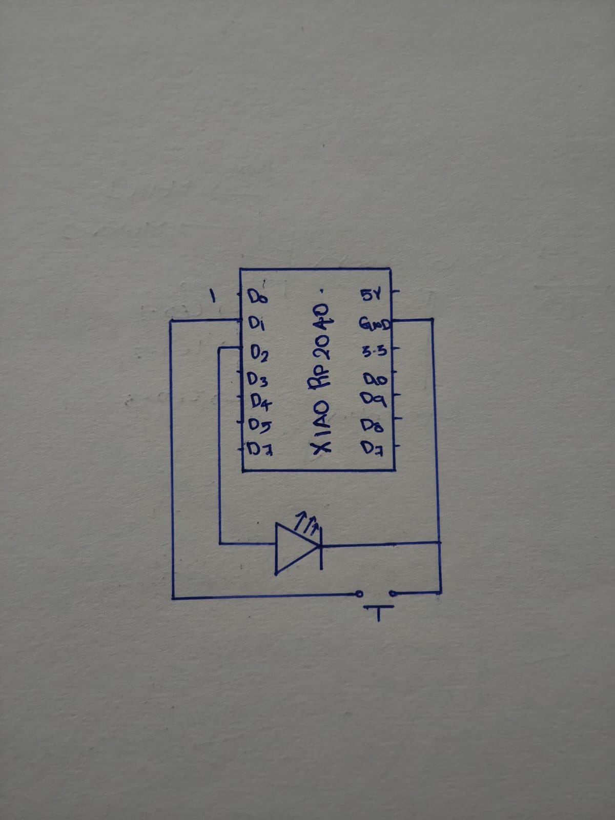
Circuit Diagram
Components Required
- XIAO RP2040
- Push button (tactile switch)
- Breadboard
- Jumper wires
- USB cable (for power + upload)
In this experiment, I interfaced a push button with the Seeed Studio XIAO RP2040 and displayed the button status on the Serial Monitor. Whenever the button was pressed, the microcontroller detected the input and printed the output message through serial communication.
Code
#define BTN D1      // D1
#define LED D2      // D2

bool lastState = HIGH;

void setup() {
  pinMode(BTN, INPUT_PULLUP);
  pinMode(LED, OUTPUT);

  Serial.begin(115200);
  delay(1000);

  Serial.println("Serial Monitor Started!");
  Serial.println("Press the button to toggle LED.");
}

void loop() {
  bool currentState = digitalRead(BTN);

  // Detect button press (HIGH -> LOW)
  if (lastState == HIGH && currentState == LOW) {
    Serial.println("Button Pressed!");

    // Toggle LED
    digitalWrite(LED, !digitalRead(LED));

    if (digitalRead(LED) == HIGH) {
      Serial.println("LED ON");
    } else {
      Serial.println("LED OFF");
    }

    delay(200); // small debounce
  }

  lastState = currentState;
}
AI Image Prompt
Prompt: "I've an LED connected to D3, and button to D0, of a xiao rp2040. I want a program which allo me click the button to turn on blinking the led and turn off when I click again, then it should print the leds status on serial monitor with diagram"
AI Tool Used: ChatGPT
The serial monitor displays the data sent from the board to the Arduino to help us understand an action's state. It prints an output that the programmer sends. Here it is the XIAO RP2040. Here, print was about the state of the LED, whether it was blinking or not.
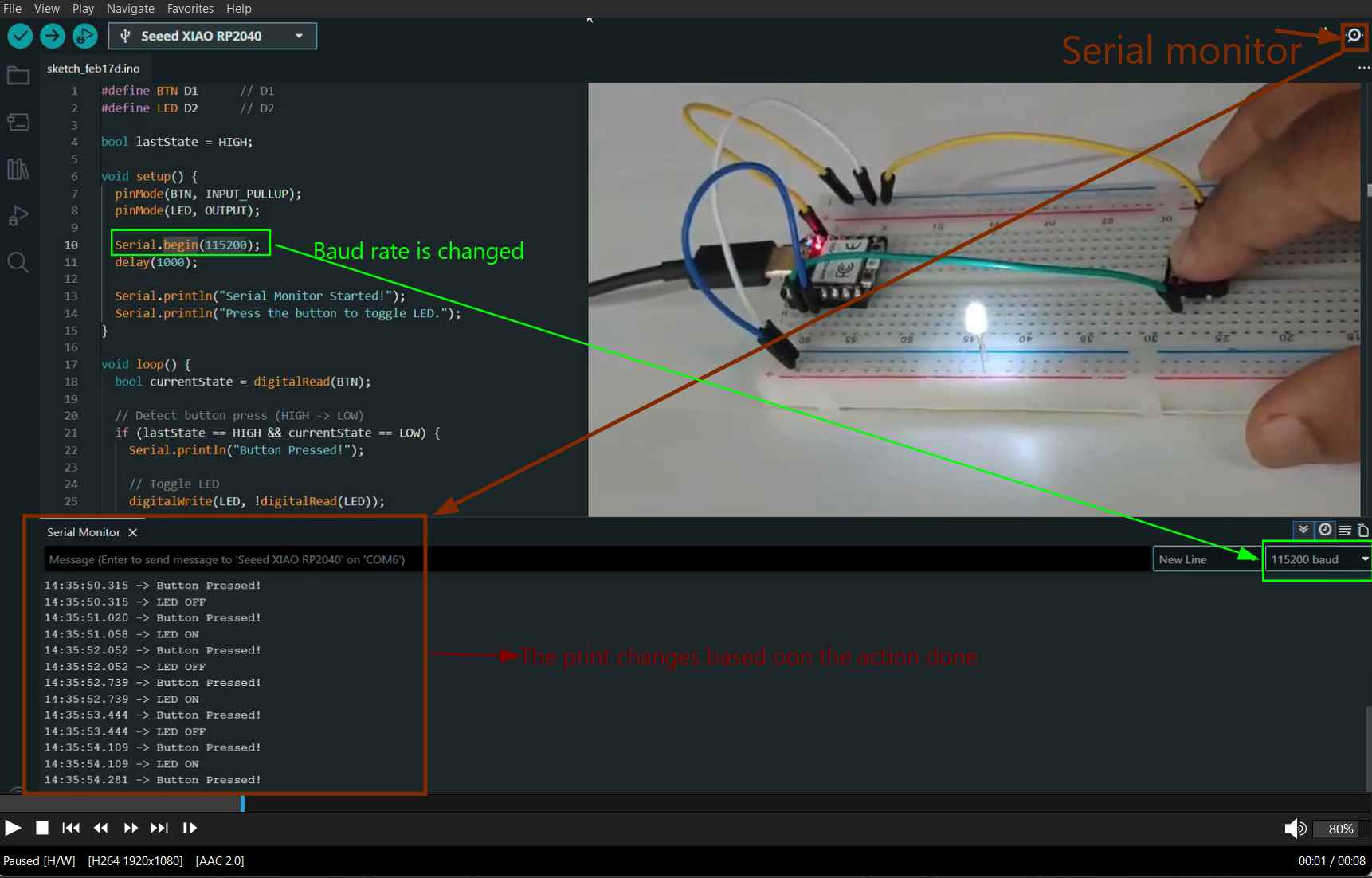
There is an icon in the top right corner. It opens the serial monitor along with the output box. Baud rateis the communication speed between the board and Arduino. That is the rate at which the board talks to the serial monitor in Arduino. The baud rate has to be adjusted according to the one in the code. If the baud rate is different, the serial monitor might not print the output in a readable format.
Seeed Studio XIAO RP2040 with MicroPython
Introduction to MicroPython
MicroPython is a version of Python made for microcontrollers. It allows us to write simple Python code and run it directly on small boards like the Seeed Studio XIAO RP2040.
Toolchain Setup
To program the board, I needed an editor that supports MicroPython. For this, I downloaded Thonny IDE.
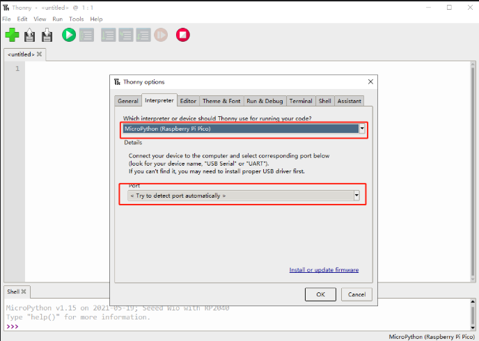
After installing and opening Thonny, I first configured the interpreter. I went to Tools → Options → Interpreter and selected MicroPython (Raspberry Pi Pico) as the interpreter, with the port set to “Try to detect automatically.” This step told Thonny that I was working with a MicroPython-based RP2040 board.
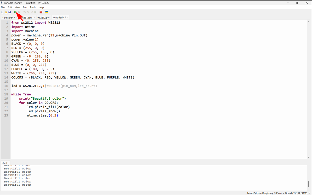
Experiment 01: RGB Rainbow Effect
In the Thonny interface, go to Tools → Options to open the settings.
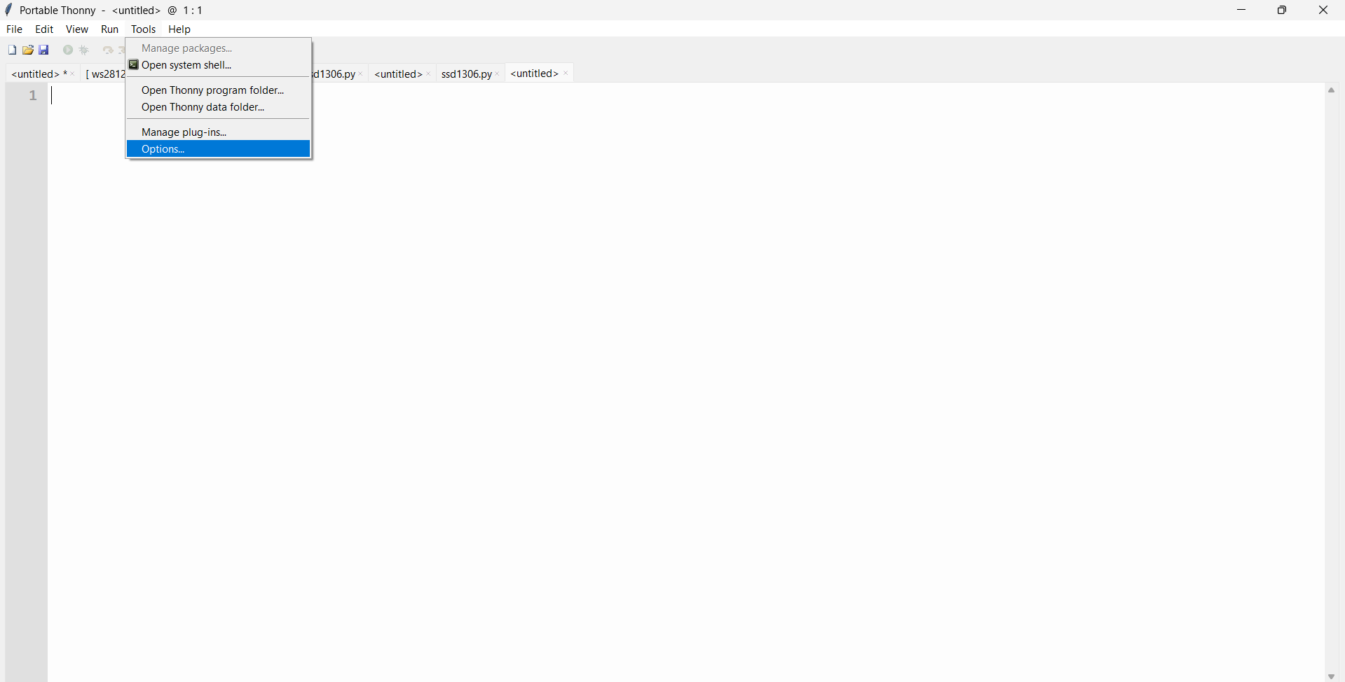
Select the Interpreter tab and set the device to MicroPython (Raspberry Pi Pico). Then choose the port option "Try to detect port automatically."
Connect Seeed Studio XIAO RP2040 to the PC and Light It Up
Step 1: Press and hold the BOOT button, then connect the Seeed Studio XIAO RP2040 to the PC using a Type-C cable. If the connection is successful, a new drive named "RPI-RP2" will appear on the computer.
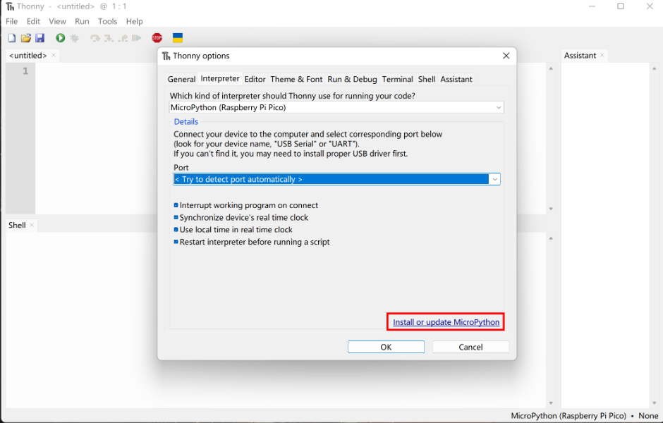
Step 2: Click Install or update MicroPython. Thonny will automatically detect the connected device and display it under Target Volume. In the MicroPython version selection below, we can leave it as the default option.
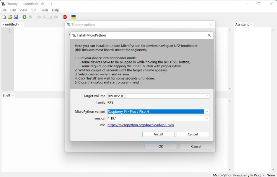
Click the Install button and wait until the installation status shows Done. After that, close the window. Once the firmware installation is complete, the following information will appear in the Thonny interface.
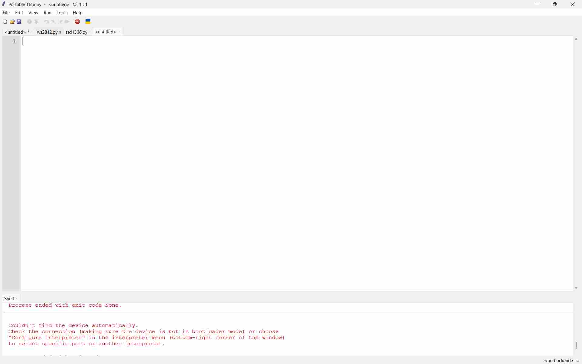
Step 4: Upload and run the code by clicking the "Run current script" button. The first time you run a program, Thonny will ask where you want to save the script file. You can choose either This Computer or Raspberry Pi Pico. If everything is working correctly, the onboard LED will blink on and off once per second. At the same time, an increasing number will be displayed in the Shell as output.
The connection is complete and now we can proceed to the other projects.
import array, time
from machine import Pin
import rp2

# Configure the number of WS2812 LEDs.
#brightness = 0.2
@rp2.asm_pio(sideset_init=rp2.PIO.OUT_LOW, out_shiftdir=rp2.PIO.SHIFT_LEFT, autopull=True,pull_thresh=24)
def ws2812():
    T1 = 2
    T2 = 5
    T3 = 3
    wrap_target()
    label("bitloop")
    out(x, 1) .side(0) [T3 - 1]
    jmp(not_x, "do_zero") .side(1) [T1 - 1]
    jmp("bitloop") .side(1) [T2 - 1]
    label("do_zero")
    nop() .side(0) [T2 - 1]
    wrap()
class WS2812():
    def __init__(self, pin_num, led_count, brightness = 0.5):
        self.Pin = Pin
        self.led_count = led_count
        self.brightness = brightness
        self.sm = rp2.StateMachine(0, ws2812, freq=8_000_000, sideset_base=Pin(pin_num))
        self.sm.active(1)
        self.ar = array.array("I", [0 for _ in range(led_count)])

    def pixels_show(self):
        dimmer_ar = array.array("I", [0 for _ in range(self.led_count)])
        for i,c in enumerate(self.ar):
            r = int(((c >> 8) & 0xFF) * self.brightness)
            g = int(((c >> 16) & 0xFF) * self.brightness)
            b = int((c & 0xFF) * self.brightness)
            dimmer_ar[i] = (g<<16) + (r<<8) + b
        self.sm.put(dimmer_ar, 8)
        time.sleep_ms(10)

    def pixels_set(self, i, color):
        self.ar[i] = (color[1]<<16) + (color[0]<<8) + color[2]

    def pixels_fill(self, color):
        for i in range(len(self.ar)):
            self.pixels_set(i, color)

    def color_chase(self,color, wait):
        for i in range(self.led_count):
            self.pixels_set(i, color)
            time.sleep(wait)
            self.pixels_show()
        time.sleep(0.2)
    def wheel(self, pos):
    # Input a value 0 to 255 to get a color value.
    # The colours are a transition r - g - b - back to r.
        if pos < 0 or pos > 255:
            return (0, 0, 0)
        if pos < 85:
            return (255 - pos * 3, pos * 3, 0)
        if pos < 170:
            pos -= 85
            return (0, 255 - pos * 3, pos * 3)
        pos -= 170
        return (pos * 3, 0, 255 - pos * 3)


    def rainbow_cycle(self, wait):
        for j in range(255):
            for i in range(self.led_count):
                rc_index = (i * 256 // self.led_count) + j
                self.pixels_set(i, self.wheel(rc_index & 255))
            self.pixels_show()
            time.sleep(wait)

By saving the code in .py format and running it in Thonny, I was able to see the output directly in the Shell. This is how I completed my first experiment using MicroPython.
For my final project development, I prefer to continue using the Arduino IDE, because it feels more structured for building complete projects. At the same time, MicroPython is also useful for quick testing and learning, and both platforms provide many examples and resources to explore.
AI Image Prompt
ChatGPT prompt: The exact prompt used is unavailable; however, the following prompt closely resembles the one provided to generate the output:
Prompt: "Genarate code for testing and understanding Thonny micropython.I have Seeed Studio XIAO RP2040 in this board there is inbuild NeoPixel LED strip using the PIO make a rain bow blinking code"
AI Tool Used: ChatGPT
What I learned in Week 04
In Week 04, I learned the basics of embedded programming and how to control real hardware using code. I understood how microcontrollers work, how GPIO pins behave as real HIGH/LOW electrical signals, and how small hardware mistakes can affect the output.
I worked with two toolchains:
- Arduino IDE (C/C++) for compiling and uploading firmware
- Thonny (MicroPython) for running scripts interactively
By the end of the week, I learned how to read a datasheet, understand pin mapping, build breadboard circuits, use resistors correctly, control LEDs (blink, aeroplane blink, chaser light), and use a push button with Serial Monitor output.
References
Software & Tools
- Arduino IDE - Programming environment for microcontrollers
- Thonny - Python IDE for beginners and MicroPython
- MicroPython - Python for microcontrollers
Hardware Documentation
- RP2040 Datasheet - Official Raspberry Pi documentation
- Seeed Studio XIAO RP2040 - Board documentation and tutorials
- Resistor Color Code Calculator - Resistor value calculator
Resources & Tutorials
- Arduino Blink Tutorial - Basic LED blinking guide
- Fab Academy Embedded Programming - Course materials
Download Files
- Blink.ino - Arduino blink code
- Code Files - All code examples