Week 03.Computer Controlled Cutting
This week is all about digital fabrication through 2D cutting, with a focus on vinyl cutting and laser cutting as tools for turning parametric designs into physical objects. We will explore how CAD and CAM workflows translate designs into cuts, learn how different machines, materials, and settings affect results, and dig into concepts like kerf, joint clearance, and press-fit construction. We will get hands-on experience making stickers on the vinyl cutter and designing a parametric laser-cut construction kit, while also working as a group to characterize our lab laser cutter and review safety. By the end of the week, we will have tangible, customizable results that reflect experimentation, iteration, and design intent.
Group Assignment
The group assignment can be found on this group assignment.
The week began with understanding lab safety protocols and the workflow, specifications, and operating parameters of the laser cutter and vinyl cutter. We focused on machine characterization by studying focus, power, speed, rate, kerf, and joint clearance.
Safety Training
Strict safety measures were followed during operation:
The group assignment can be found on this group assignment.
Process
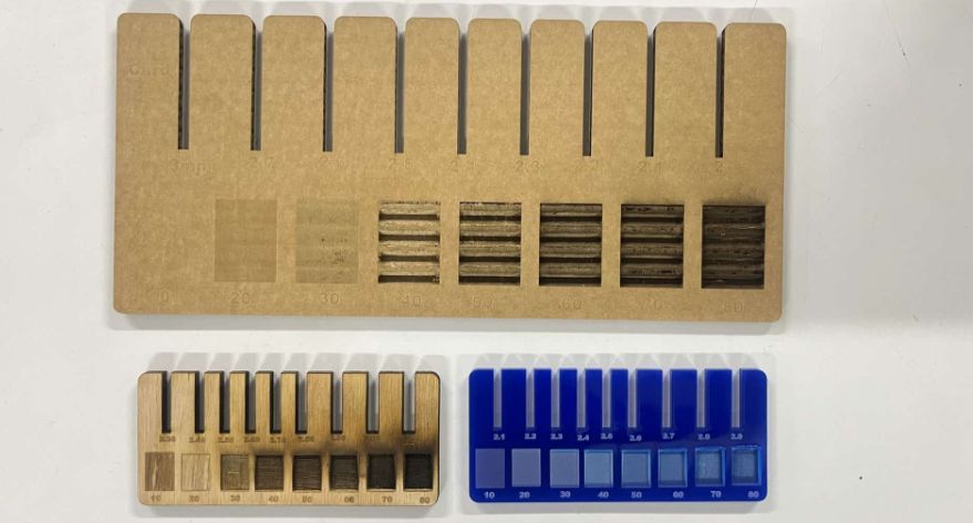
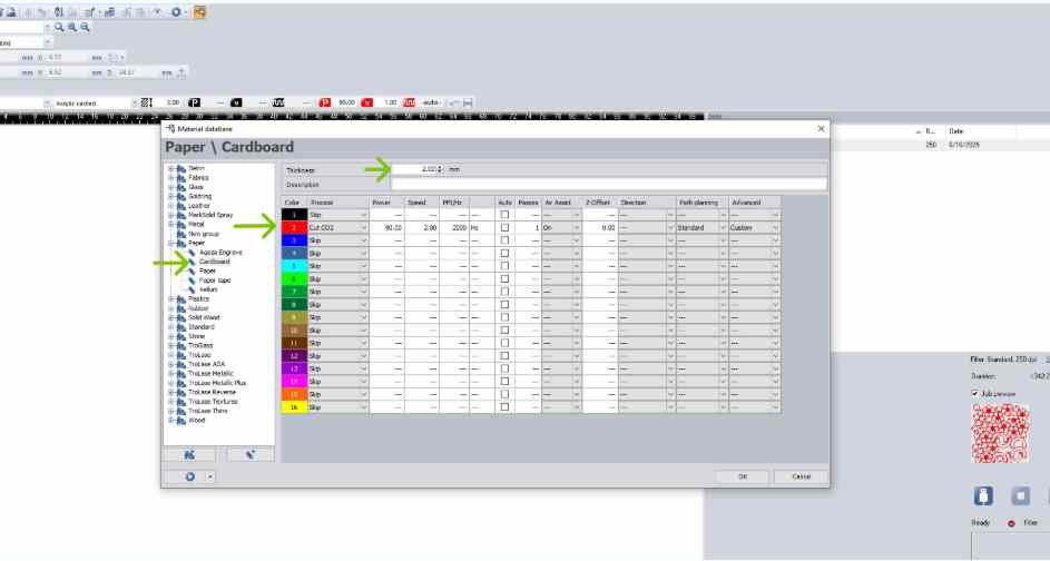
Through hands-on testing, I developed a clearer understanding of how parameters such as power, speed, and focus affect cutting and engraving performance. A key concept explored was kerf, the material width removed by the laser, which directly impacts press-fit assemblies. Before cutting, design files were color-coded using standard conventions to distinguish between cutting and engraving operations. To obtain the kerf value, we laser-cut a 40 × 40 mm square with a 20 × 20 mm inner cutout from cardboard. After cutting, we measured the inner dimension of the larger square and the outer dimension of the smaller square. The difference between these two measured values gave the total kerf, which was then divided by two to calculate the kerf for the material. We also experimented with engraving settings, observing that lower power produced lighter surface marks, while higher power and slower speeds resulted in deeper engravings. This helped in understanding how to balance power and speed to achieve desired engraving effects on different materials. These tests were then repeated on birch wood and acrylic sheet as well
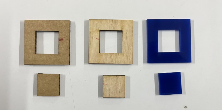
The final values we figured for the parametric press-fit pieces for Cardboard are:
- Thickness: 3 mm
- Compression: 0.2 mm
- Kerf: 0.3 mm
The effective kerf was found to be approximately:
- 0.14 mm for wood
- 0.1 mm for acrylic
Individual Assignment
Vinyl Cutting
Making Stickers using Vinyl Cutter
The next part of our assignment was to create stickers using vinyl sheets. For this task, we used the
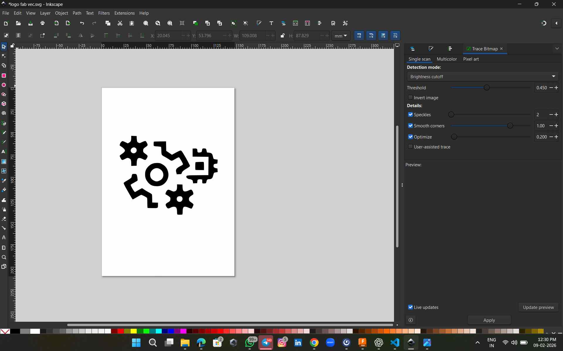
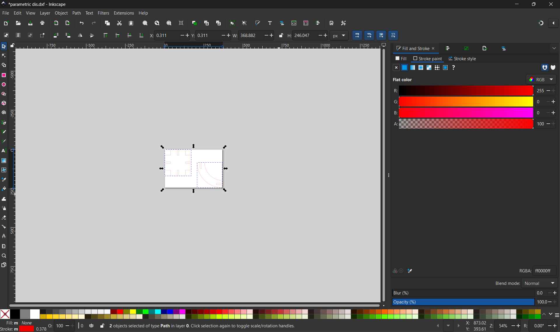
For this design, I used Inkscape for creating and editing the vector graphics. For more detailed documentation and design process, you can visit my Week 02 Documentation .
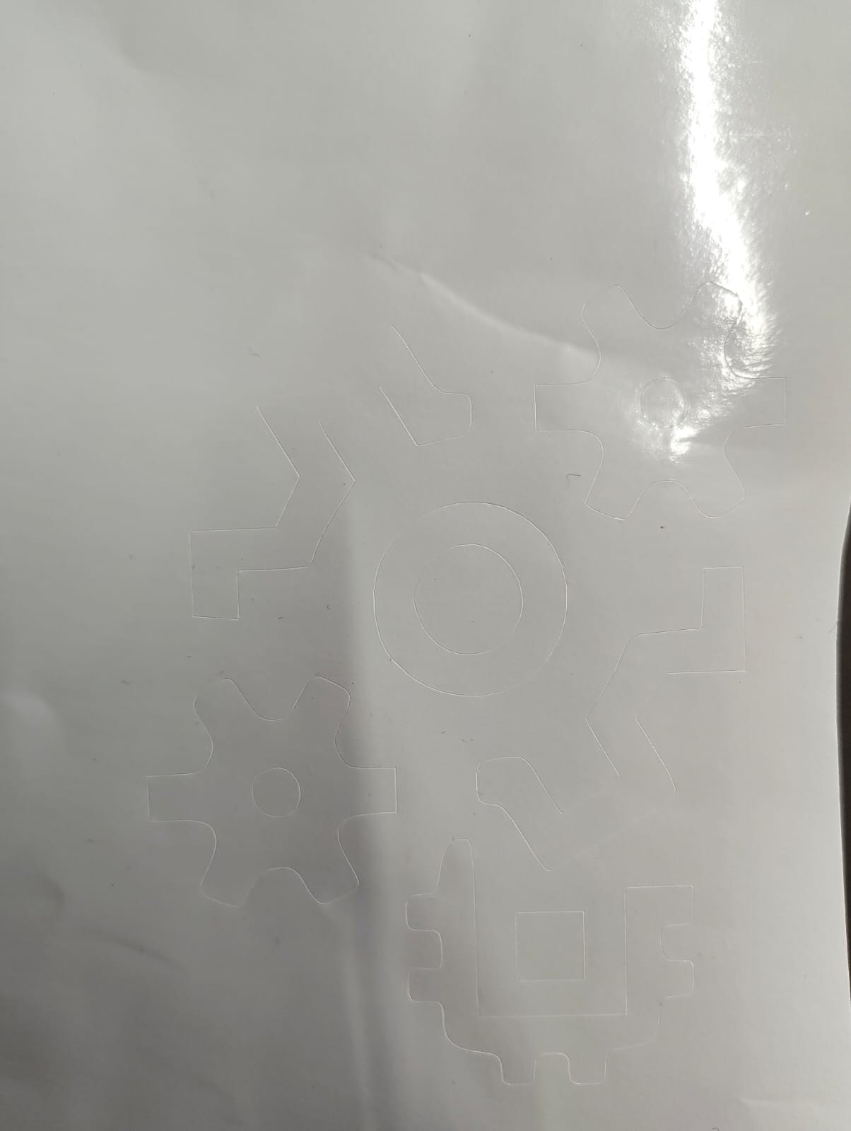
Before using the machine, we first needed to prepare the sticker graphics. For this assignment, I selected I made a second sticker design based on a mechanical shaft and gear graphic sourced from Google, and prepared it for vinyl cutting.
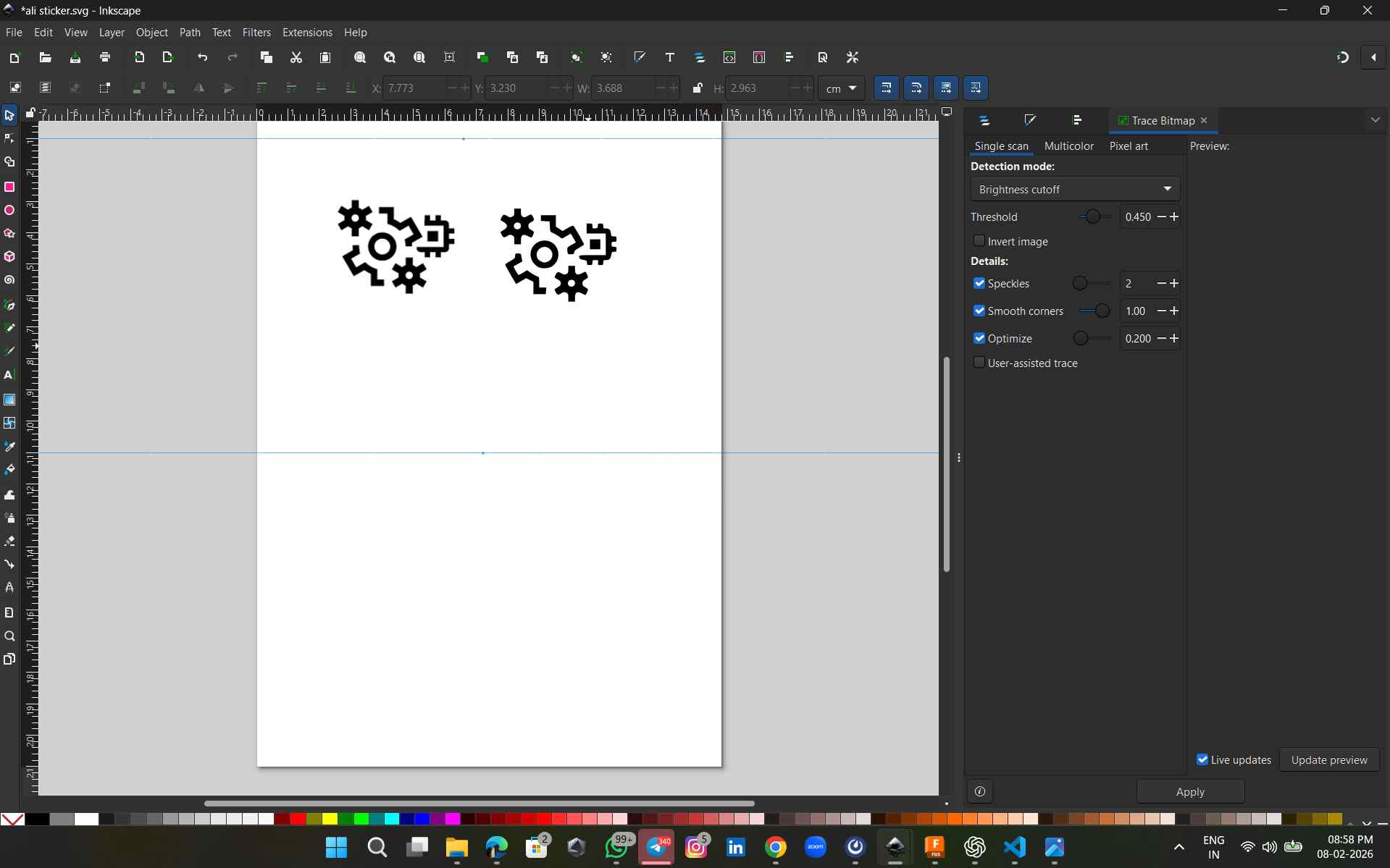 image source
To make sure the design edges were not cut off, I added an offset stroke of about 2 3 mm around the traced image. After that, I resized the canvas (Ctrl + Shift + R). Then I removed the stroke since it was only needed for spacing. Finally, I selected the full design and saved it as an SVG file.
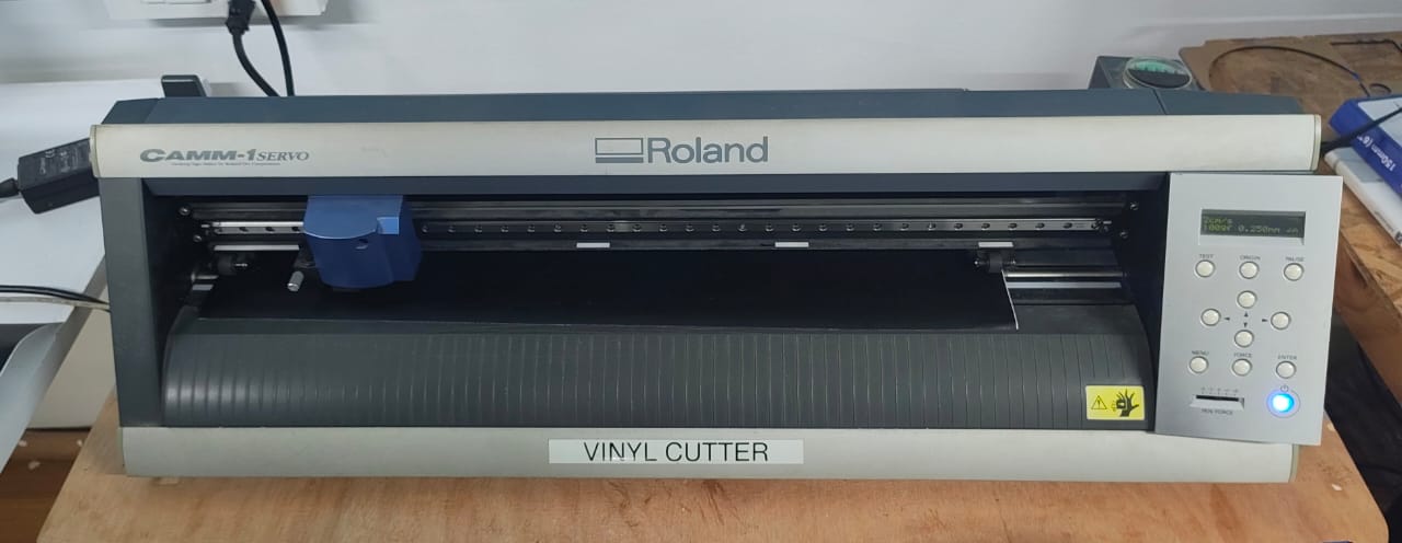
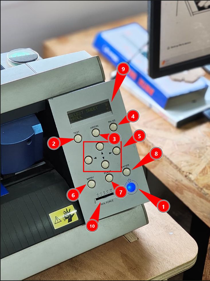
We can select the material feed type such as roll, sheet, or piece. From the control panel, we can also set the origin point, and adjust the cutting force and cutting speed based on the material.
Vinyl Cutter Control Panel Settings
Roland CAMM-1 Servo machine settings
Workflow in ModsCE for the Roland GX-24 Vinyl Cutter
To follow the Software Workflow (Mods), connect the machine with the computer. I used https://modsproject.org/ .
In ModsCE, the workflow begins at Selection by right-clicking the canvas to navigate through Programs → Open Program → Roland → Vinyl Cutter → GX-24, which loads the appropriate cutting environment for the machine.
Once the program is loaded, the SVG file is imported during the Conversion stage, where the offset is set to 1 to ensure the cut paths are correctly interpreted and scaled for the cutter.
With the file prepared, we move to Origin, where the tool head is manually positioned to the desired start point on the vinyl sheet, and the Origin button on the GX-24 is long-pressed to register that position as the reference point for the cut.
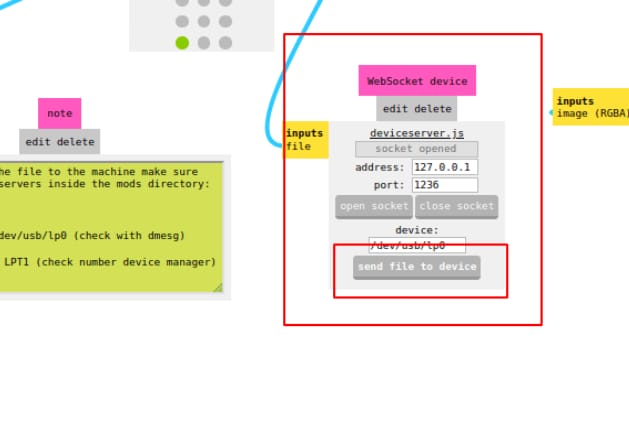
Finally, at the Send stage, the file is transmitted to the cutter using the WebSocket serial node, which communicates directly with the GX-24 to initiate the cutting operation.
Next, we opened the MODS software and imported the SVG file we prepared. MODS is an open-source, browser-based tool developed by MIT that converts design files such as SVG, PNG, and DXF into machine-readable formats. It allows us to customize toolpaths, set cutting parameters, and send commands directly to machines like vinyl cutters, laser cutters, and CNC machines. After importing the design, we set the required cutting parameters in MODS before sending the file to the vinyl cutter
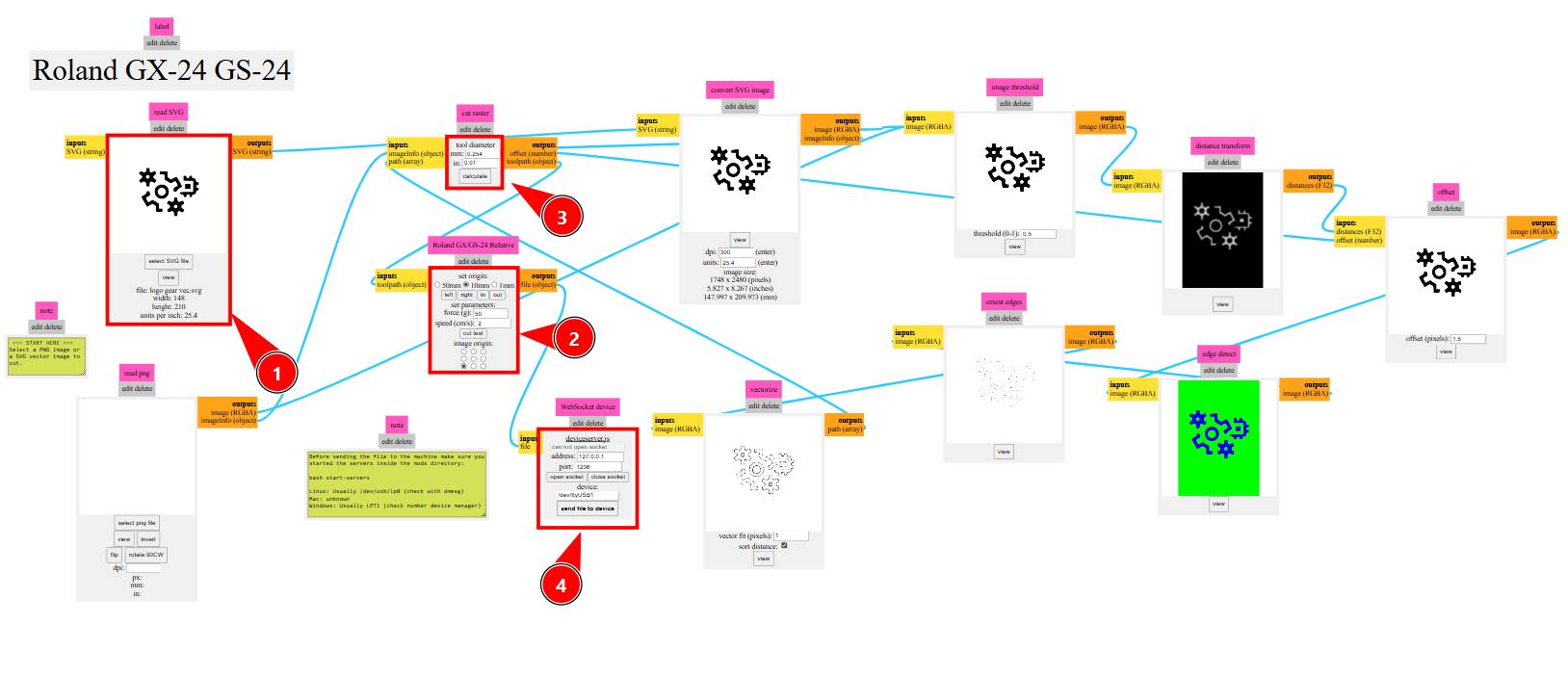
Here are the steps to use mods project.
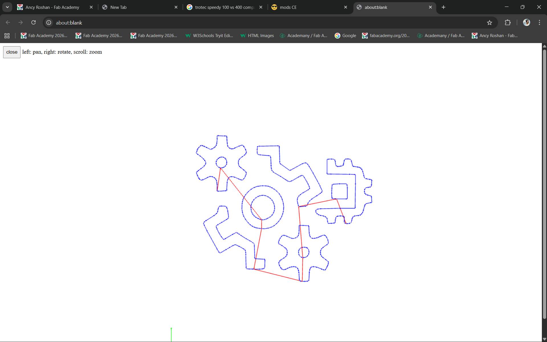
If we Click the view button in 'vectorize module' after calculation that will show the vinyl cutter tool path in New Tab
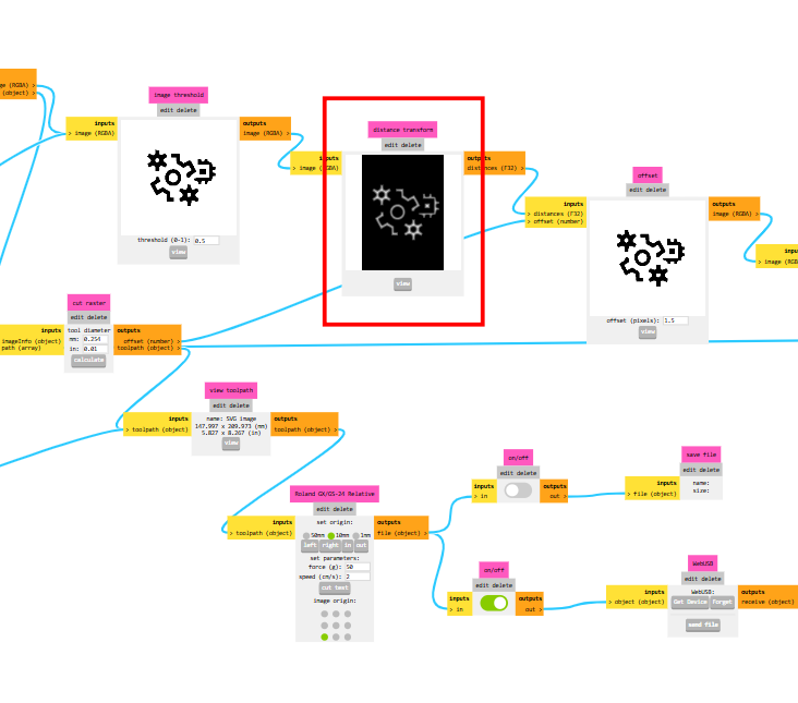
The other modules shows offset and how much detail we can get and etc...
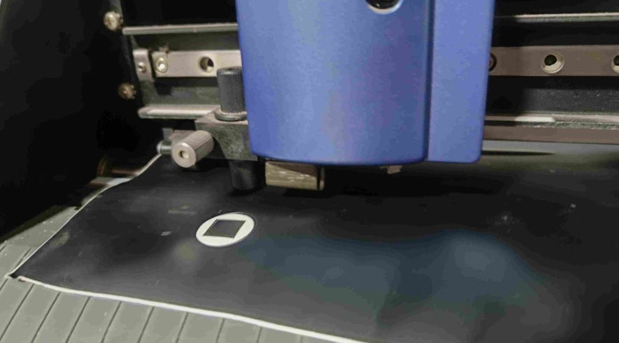
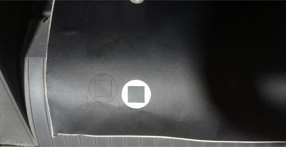
We needed to set the machine origin based on the vinyl roll position. After setting the origin, I made a few test cuts to check and adjust the cutting depth.
Cutting Parameters
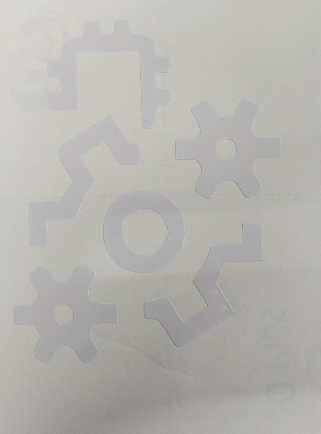
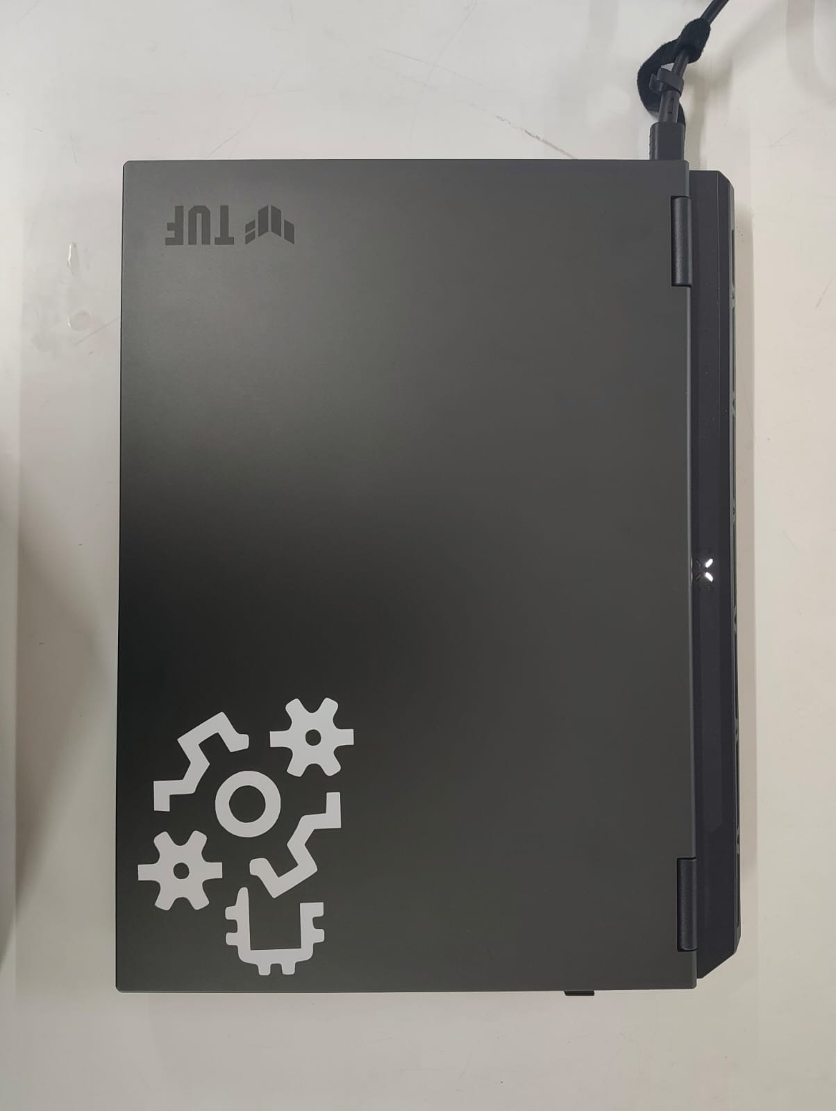
I decided to apply the first sticker on my lap top . First, I removed the unwanted vinyl parts (weeding). I used a cooling film as transfer sheet peeled off the backing, and carefully placed it on top of the vinyl sticker
Then, I placed the vinyl along with the transfer paper onto my laptop. After positioning it properly, I slowly peeled off the transfer paper while ensuring the vinyl stayed on the surface smoothly without creating any air bubbles.
I would like to create more sticker designs in the future, because I really enjoyed this process and found it fun.
Making a parametric construction kit.
Trotec Speedy 100
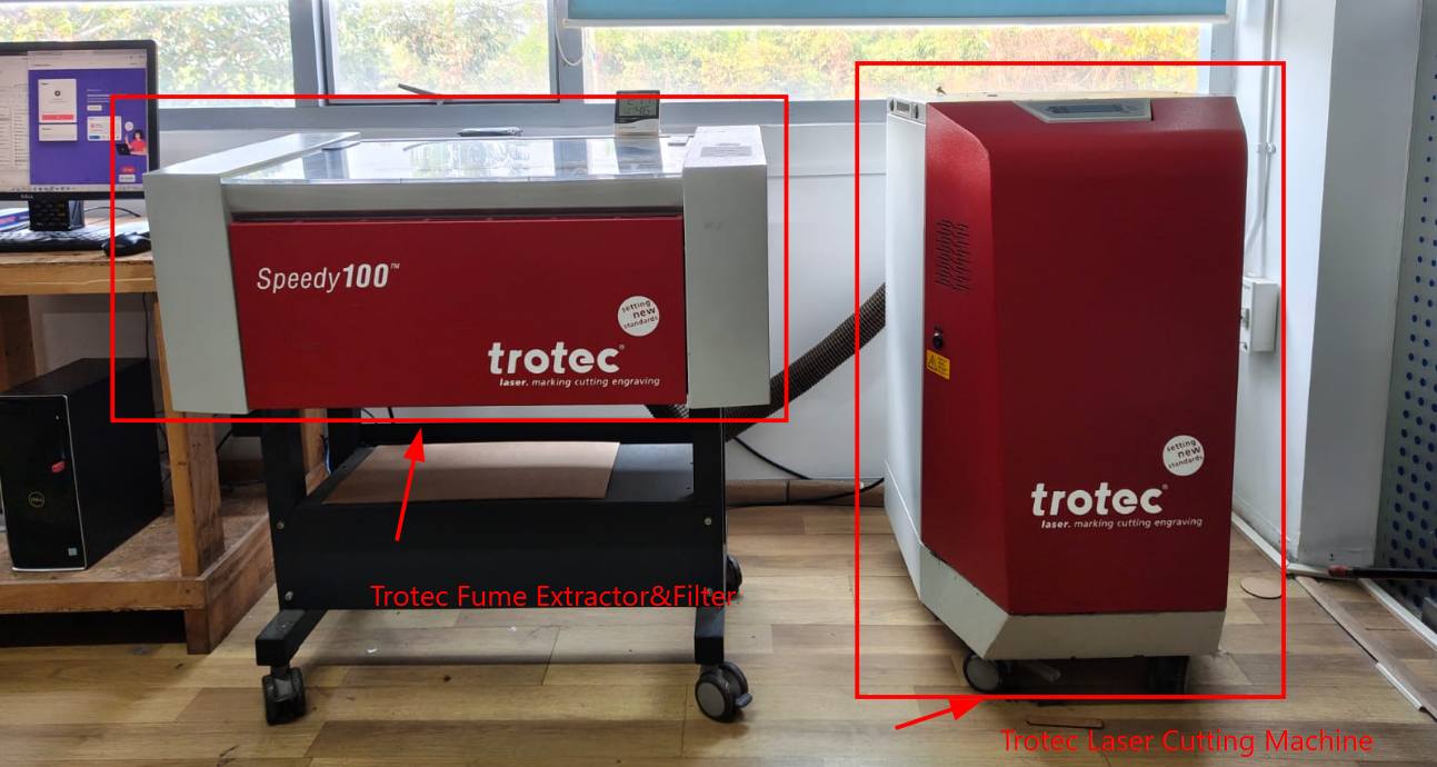
The Trotec Speedy 100 Flexx is a high-performance machine used for both laser cutting and laser engraving. It belongs to Trotec Speedy series, which is well known for its quality and reliability.
Trotec Speedy 100 vs Speedy 400
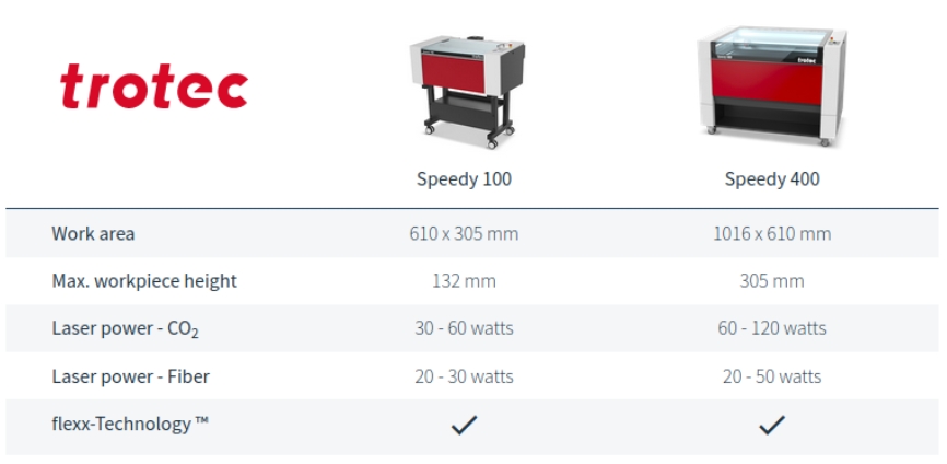
The Speedy 400 machine at the Super FabLab is significantly more powerful than the Speedy 100 and also features a larger work area, as shown above.
The feature means the machine combines both a CO2 laser and a fiber laser in one system. This allows it to process a wide range of materials using a single machine.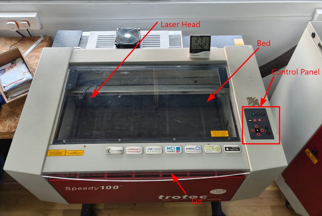
To cut materials of different thicknesses, the laser head and the workpiece must be kept at the correct focus distance. This tool is used to set the focus distance on the Speedy 100 laser machine. We must adjust the focus manually each time we use a different material thickness.
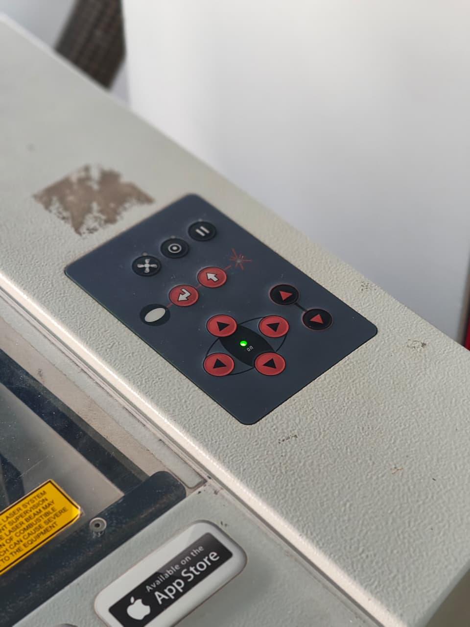
This is the control panel used to move the laser head and select the work area. It also includes other controls such as the fan control, pause button, and Z-axis bed leveling options.
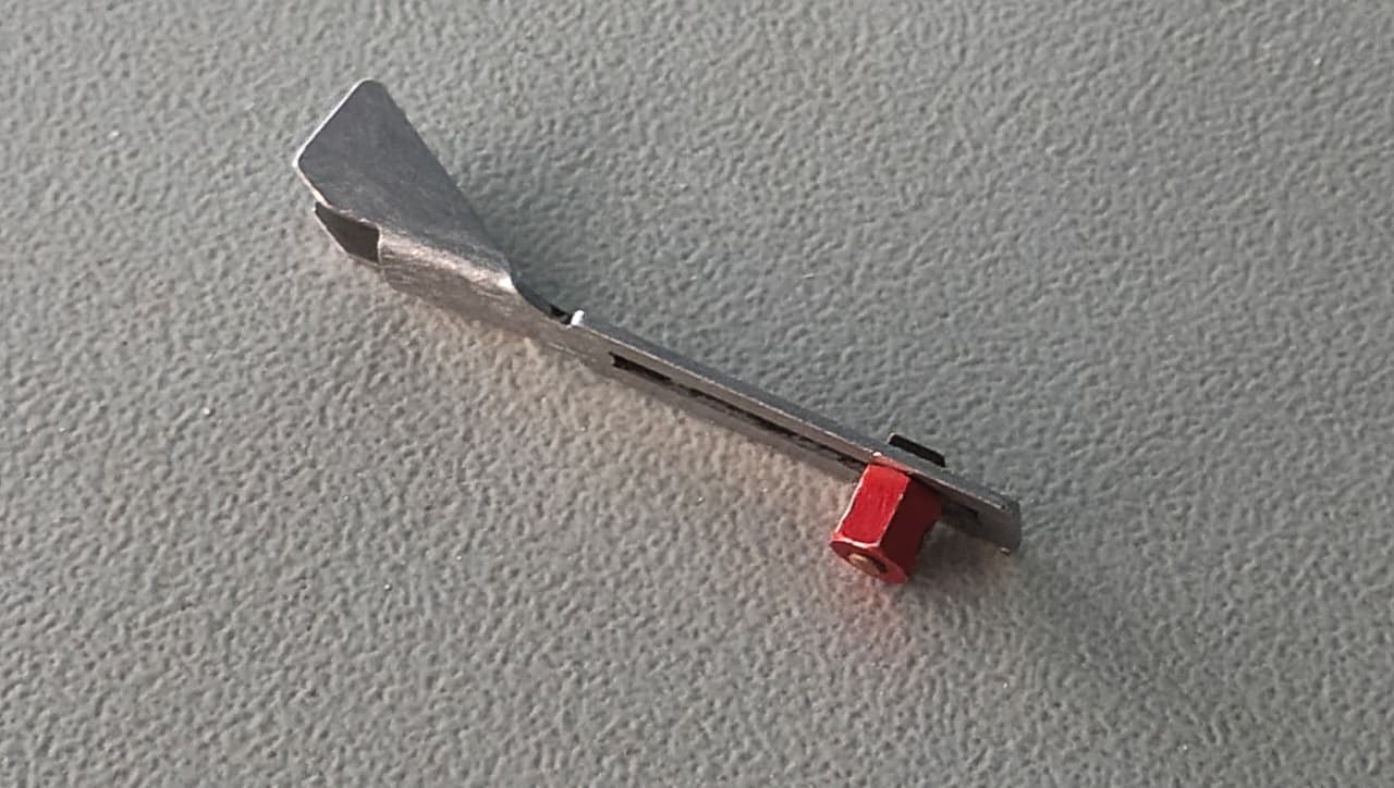
To cut materials of different thicknesses, the laser head and the workpiece must be kept at the correct focus distance. This tool is used to set the focus distance on the Speedy 100 laser machine. We must adjust the focus manually each time we use a different material thickness.
Parametric design
We had to design a shape that could be repeated and joined in different ways. I used Fusion 360 and created the model using the Modify the Change Parameters tool. This method is useful because the dimensions can be changed easily by updating the parameter values, instead of editing the sketch manually. It is a powerful feature and can be used in many different design applications.
So, if you change one value, the whole model updates automatically
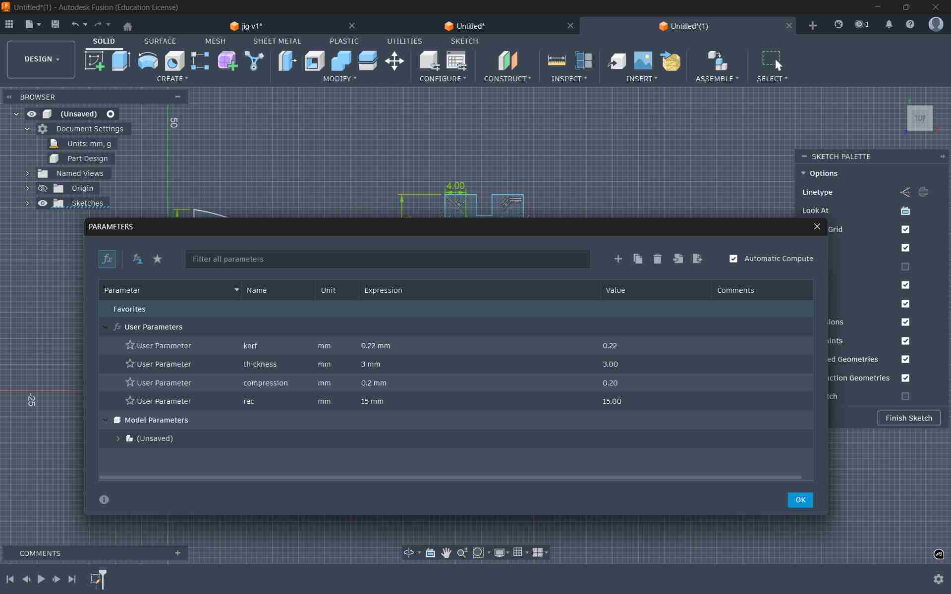
parameters
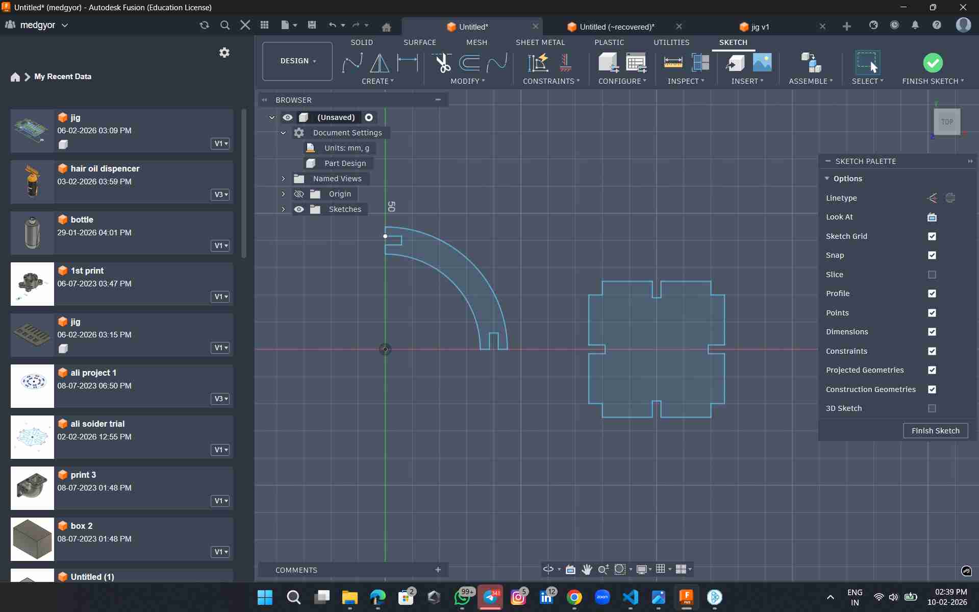
I began by setting the parameters first. Go to modify and at the bottom of the drop down you can see change parameters.When you click on it you will be taken to a dialogue box where the user can set the parameters. I set the values for the thickness of the material, kerf value of the materials and compression .I then took these parameters to make equations to set the width of the slot.
You can type in the parameter that was set previously into the dimensions . The software will automatically resize the dimension to fit the parametric values
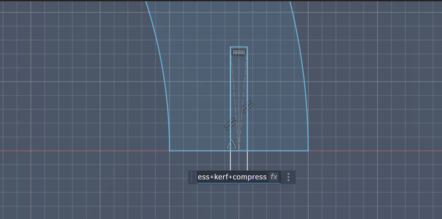
then i gave value of thickness+kerff+compression

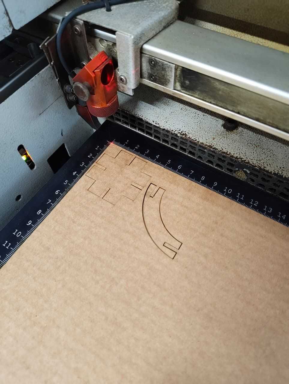
Operating the laser machine
Job Control
Click Ready to give the print .The laser will start the cutting process.
Click Ready to give the print .The laser will start the cutting process.
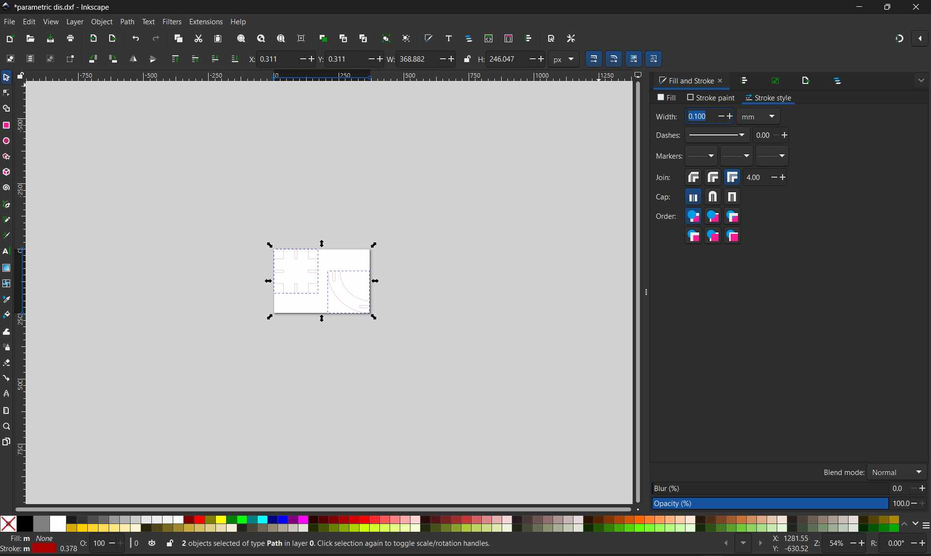
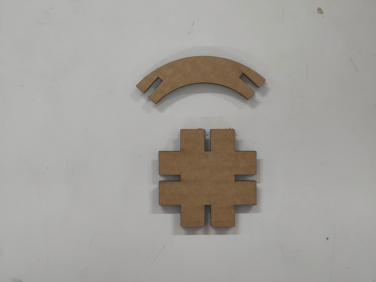
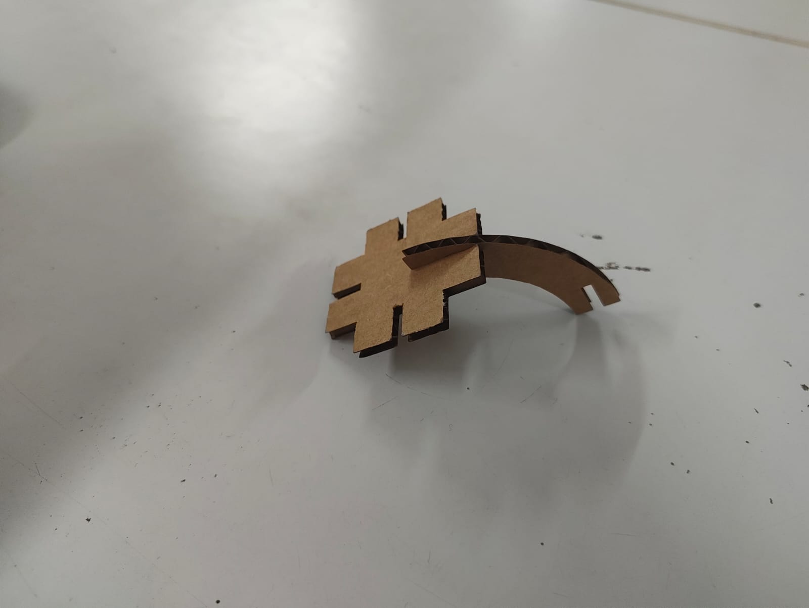
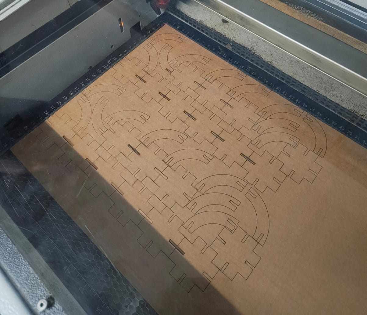
After removing the pieces from the cardboard, I checked the press-fit. The fit was satisfactory, so I used DeepNest to generate multiple copies of the shapes and arrange them efficiently to reduce material waste.
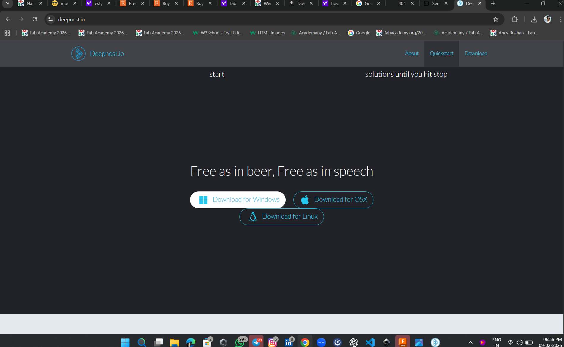
I used Deepnest.io.io to arrange the design on the cardboard efficiently, which helped reduce material waste and save space.
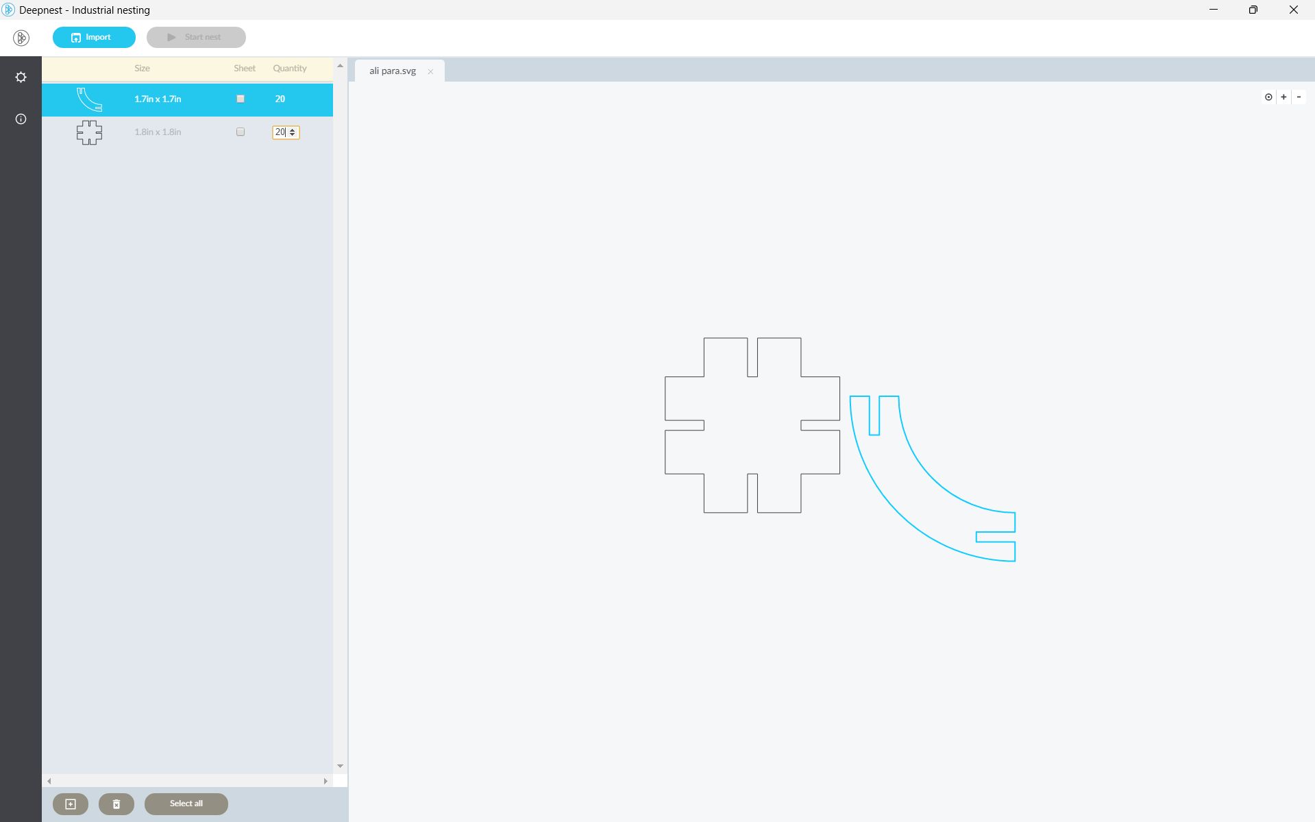
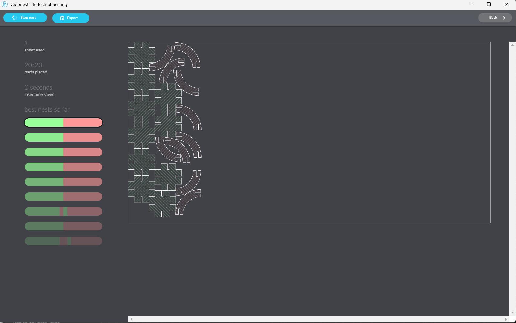
In Deepnest software, I entered the required quantity, and the software automatically generated and arranged the parts closely to each other without wasting material.
After cutting, the press-fit components were ready for assembly
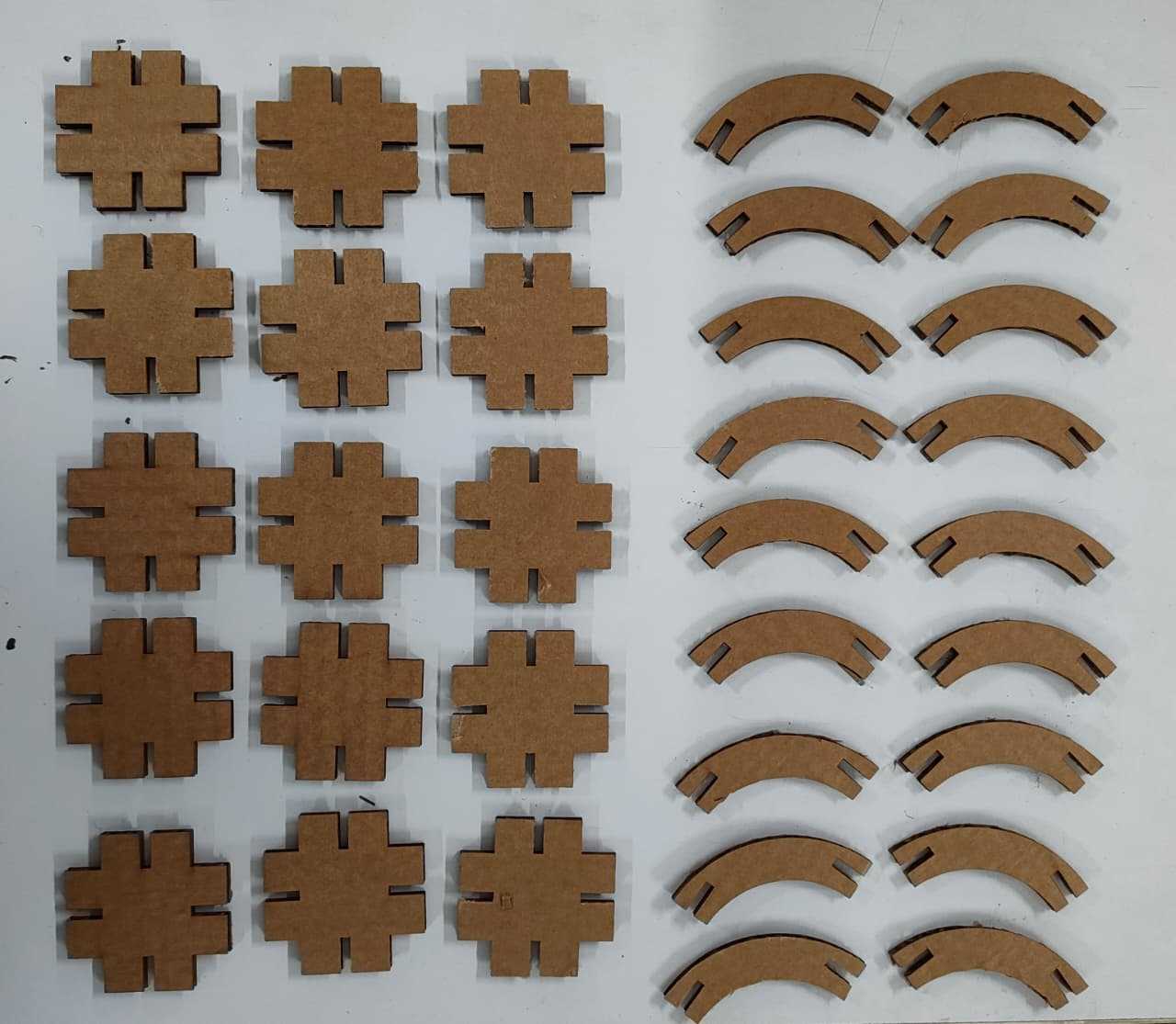
Finally the pieces were cut and i started to create intresting figures with the kit i made.
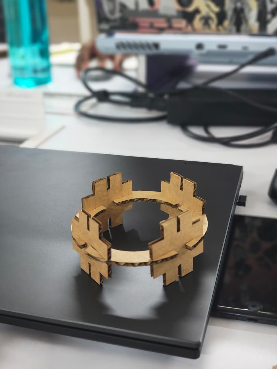
Hero Shot
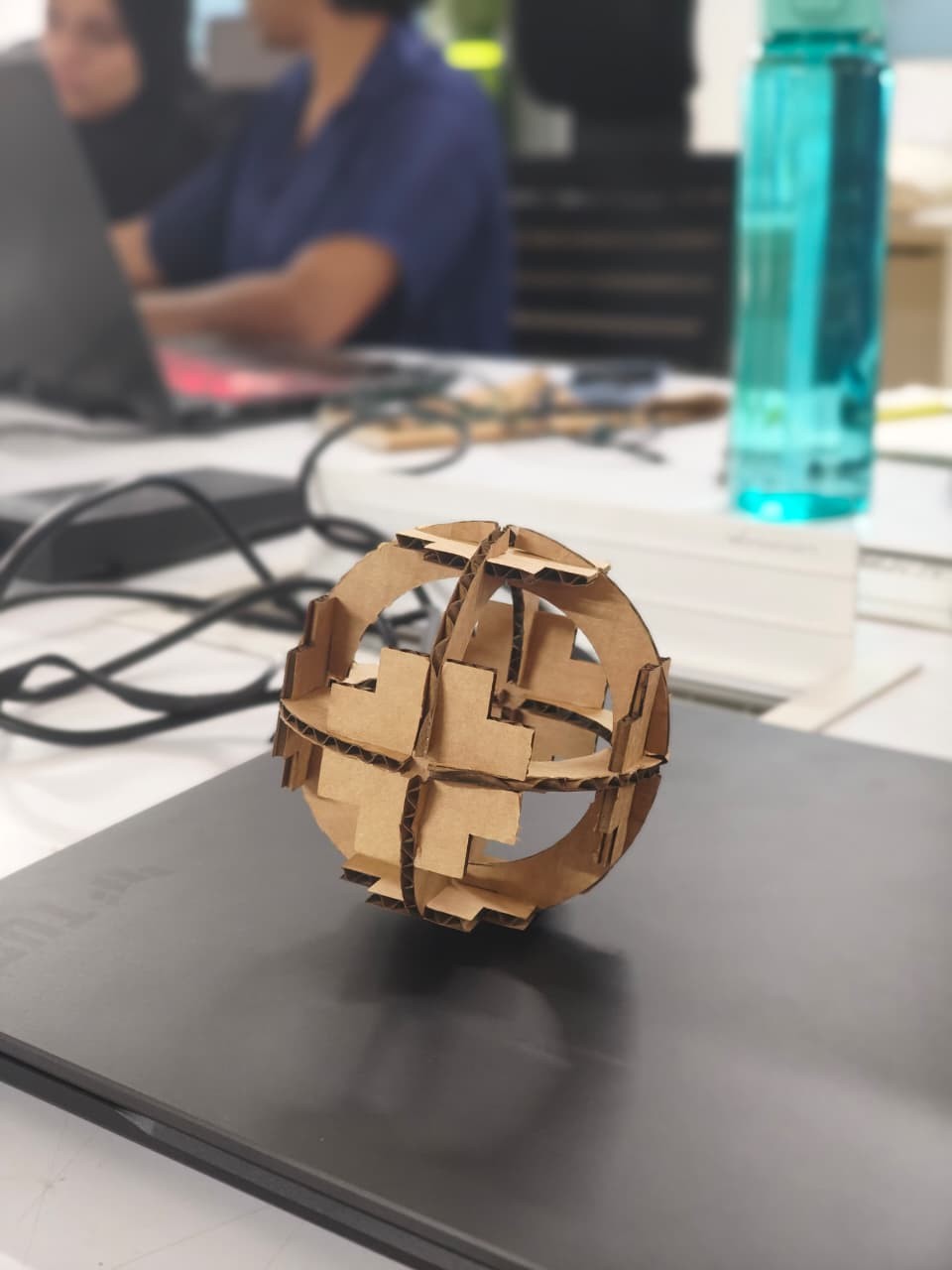
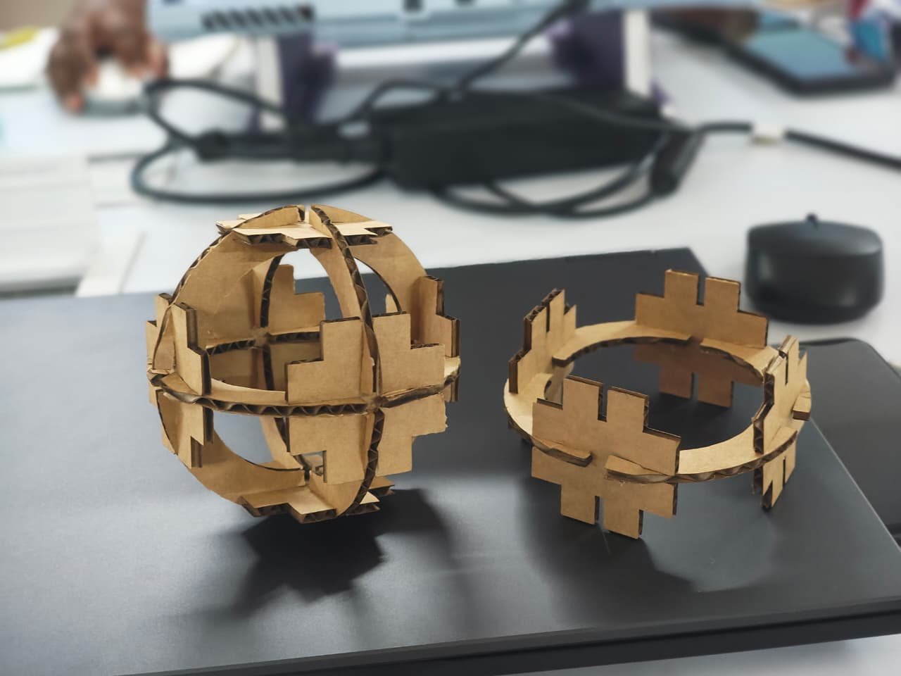
Overall, this assignment helped me understand how to operate the machine safely and achieve precise cuts for our designs. I also learned how to use parametric values to create CAD models. I really enjoyed this week of parametric design. I made two models, and they are shown above.
References
Software & Tools
- Fusion 360 - Parametric CAD design software
- Inkscape - Vector graphics editor for SVG files
- Deepnest.io - Nesting software for material optimization
- MODS - MIT open-source fabrication software
Machines & Equipment
- Trotec Speedy 100 - Laser cutting machine
- Roland GX-24 Vinyl Cutter - Vinyl cutting machine
Resources & Tutorials
- Press-fit Construction Kit Tutorial - Instructables guide
- Group Assignment - Laser cutter characterization
- Fab Logo - Logo resource
Download Files
- Download File -design file