Week 2 Computer aided design
Week 2 focuses on exploring a possible final project ideaImage Editors
Rasters & Vectors
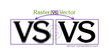
Source Reference: Raster vs Vector Graphics
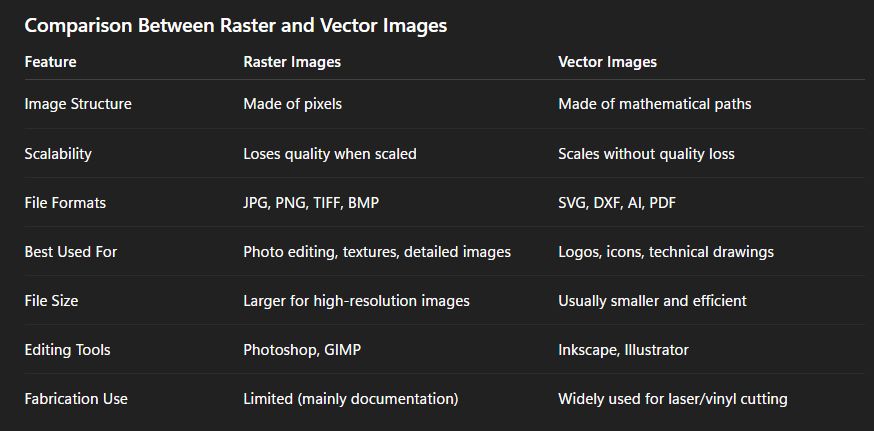
Comparison Between Raster and Vector Images
Understanding 2D Design
Inkscape
Inkscape is a free and open-source software used for vector design. It works with SVG files and creates designs using shapes and lines instead of pixels. Because of this, we can resize the design without losing quality. It is mainly used for making logos, icons, and technical drawings. This week, I studied many software tools, and Inkscape was one of them. I found it very simple and easy to use.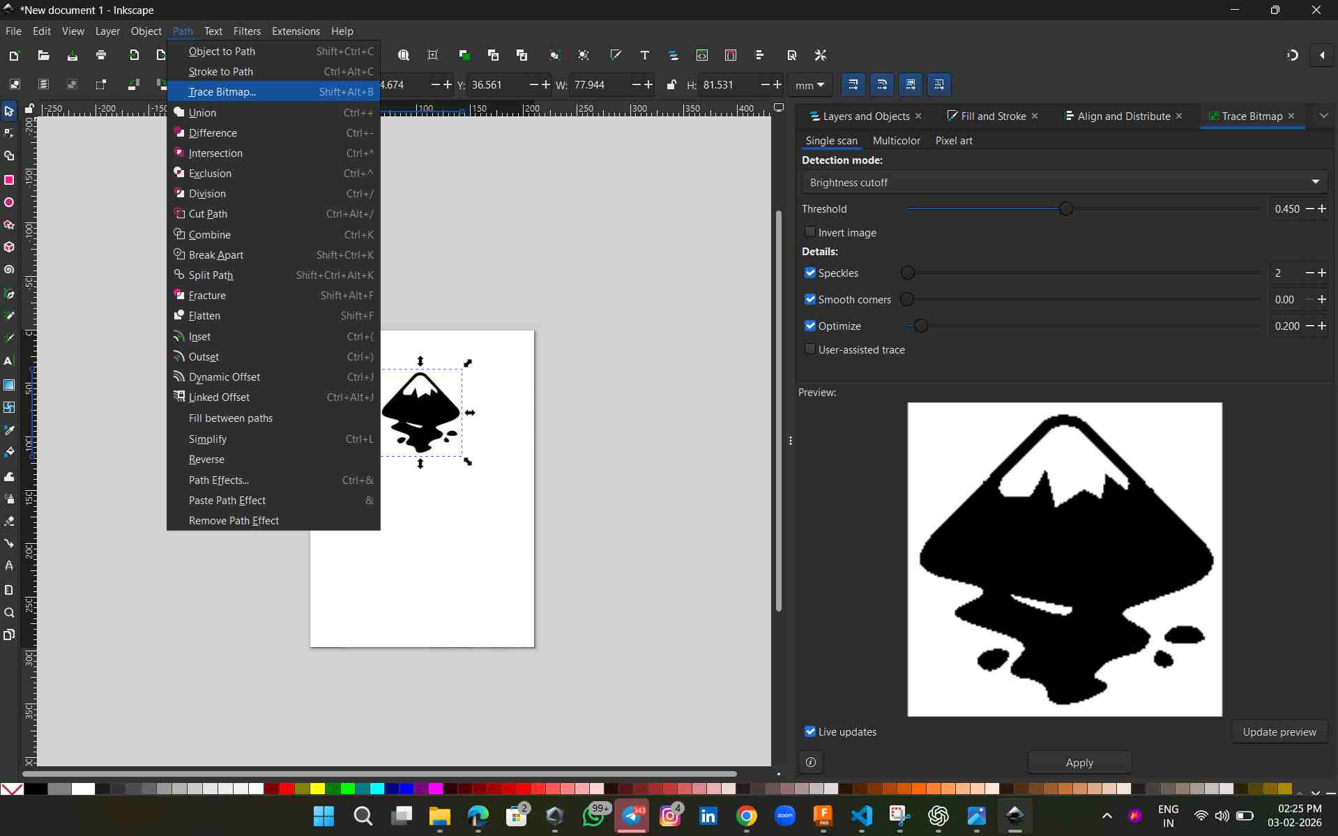
Source Reference: Inkscape Logo
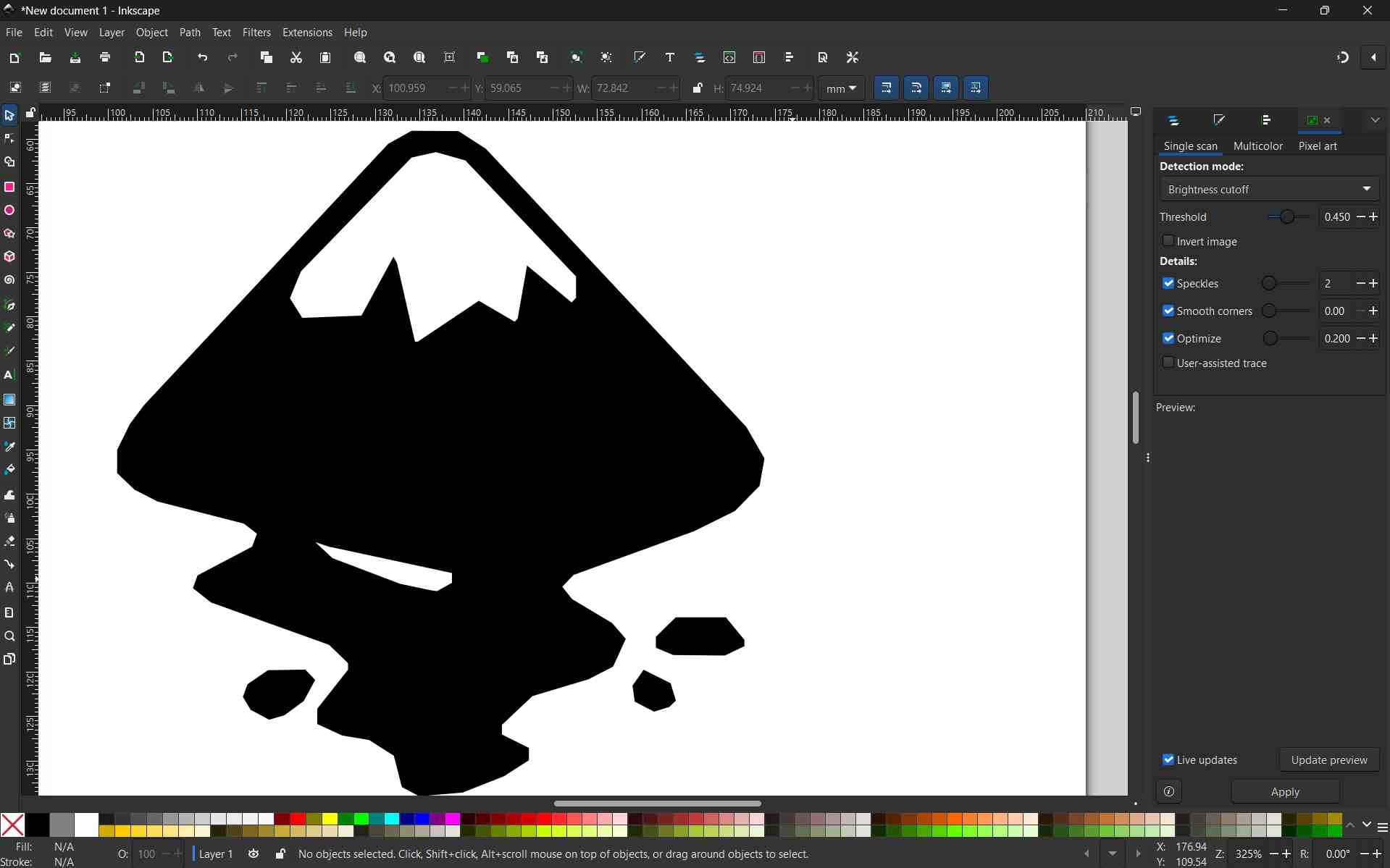
For this exploration, I downloaded a png image of Bubbles from The inkscape logo from online I tried using the 'Trace Bitmap' option on Inkscape to convert Rastor images to Vector, a very simple way to explain this would be to say how you can turn your images to high quality line work without them getting pixelated while zooming in.
See how the quality is being compramised while zooming in, you can see the individual pixels if you zoom in further.
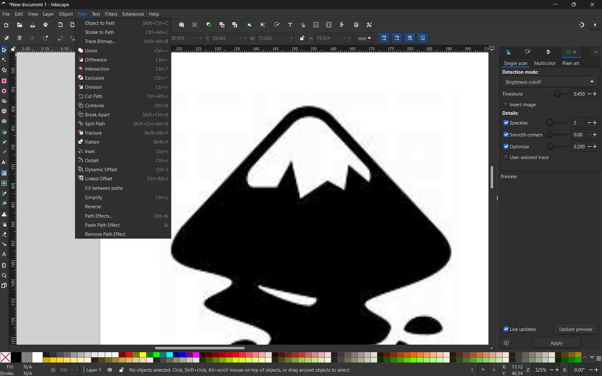
The above image shows the zoomed-in view of the image after tracing the bitmap; see how the line quality has become sharper. This little exercise explains the concept of Raster and Vector images. The main difference between raster and vector graphics lies in how they are constructed: raster images are made of a grid of tiny colored pixels, while vector graphics are built from mathematical paths (lines and curves).
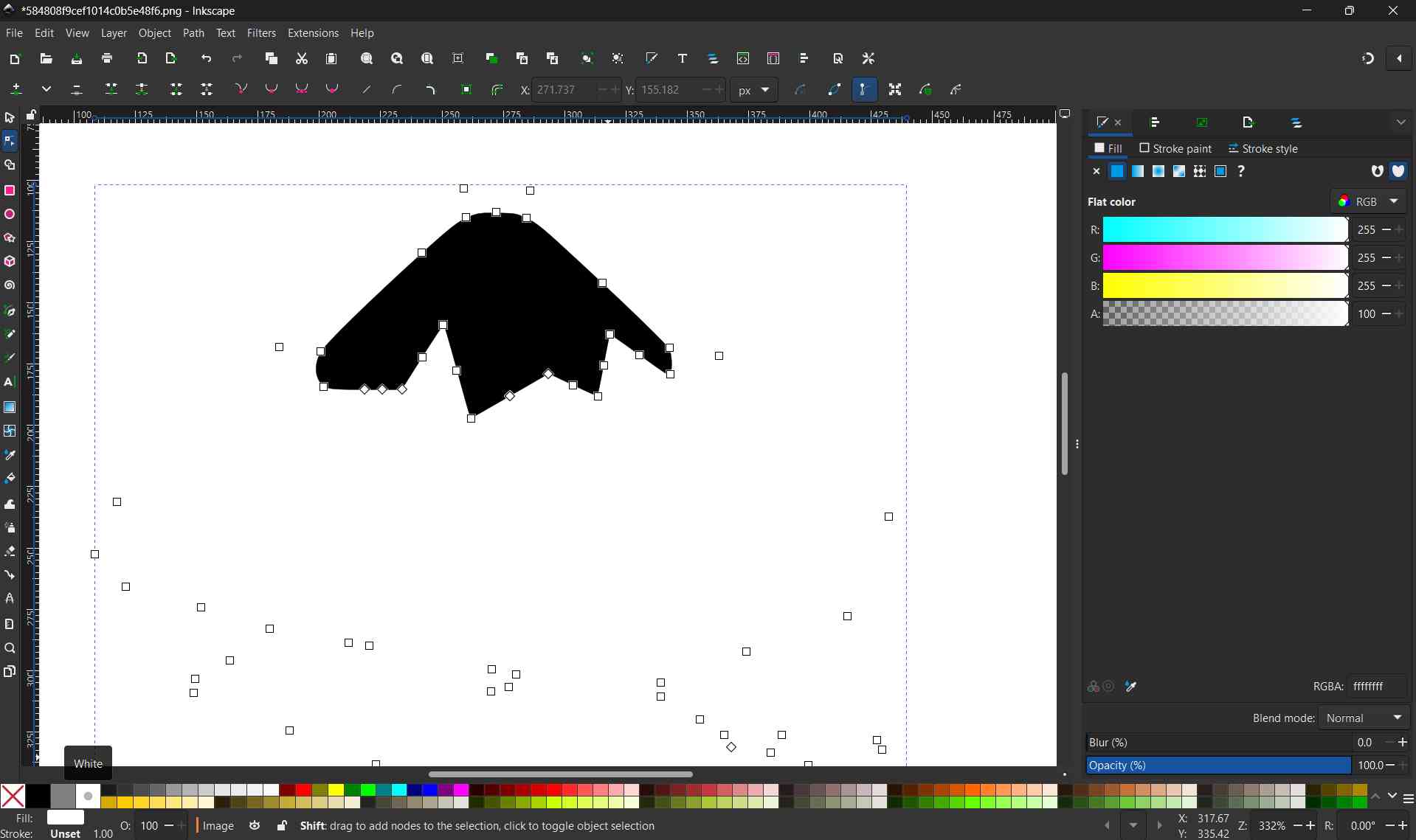
i selected node tool clicked and draged the shape to fill the colour using the fill Bucket tool
using node tool i select area i need to be reversed
using rectangle too i created a suare and fill with background colour
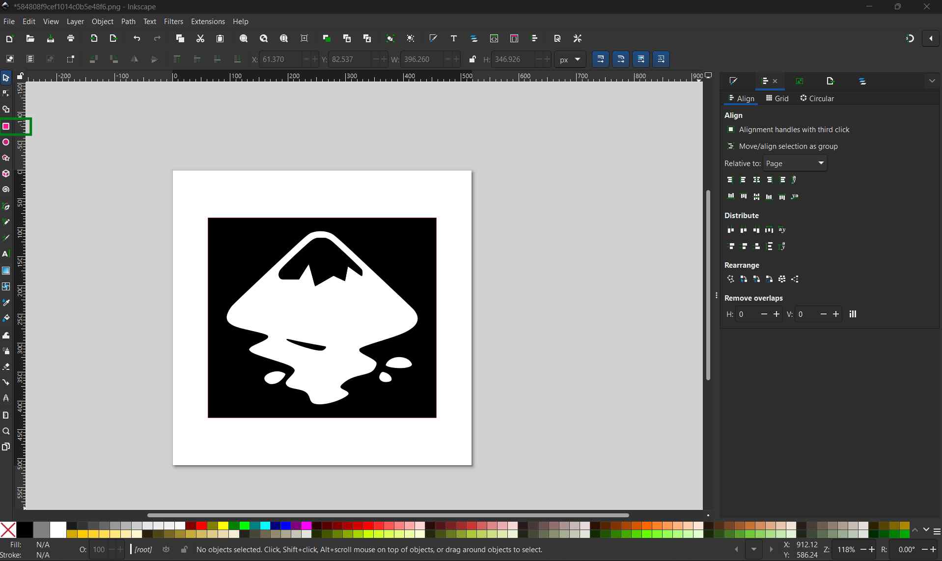
after that i aligned all in centre
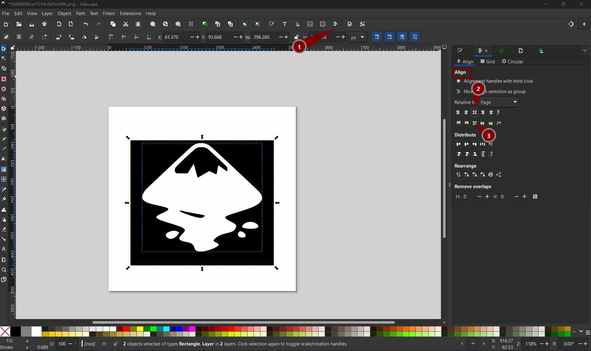
Photo pea
In this week, we studied three software tools for 2D design. Photopea is one of them. It is free and open for everyone to use. For me, it is very easy and nice to use. I also learned many new shortcut keys while working in Photopea.
i opened the browser i was given options to create a new projecct or open an existing file from my system
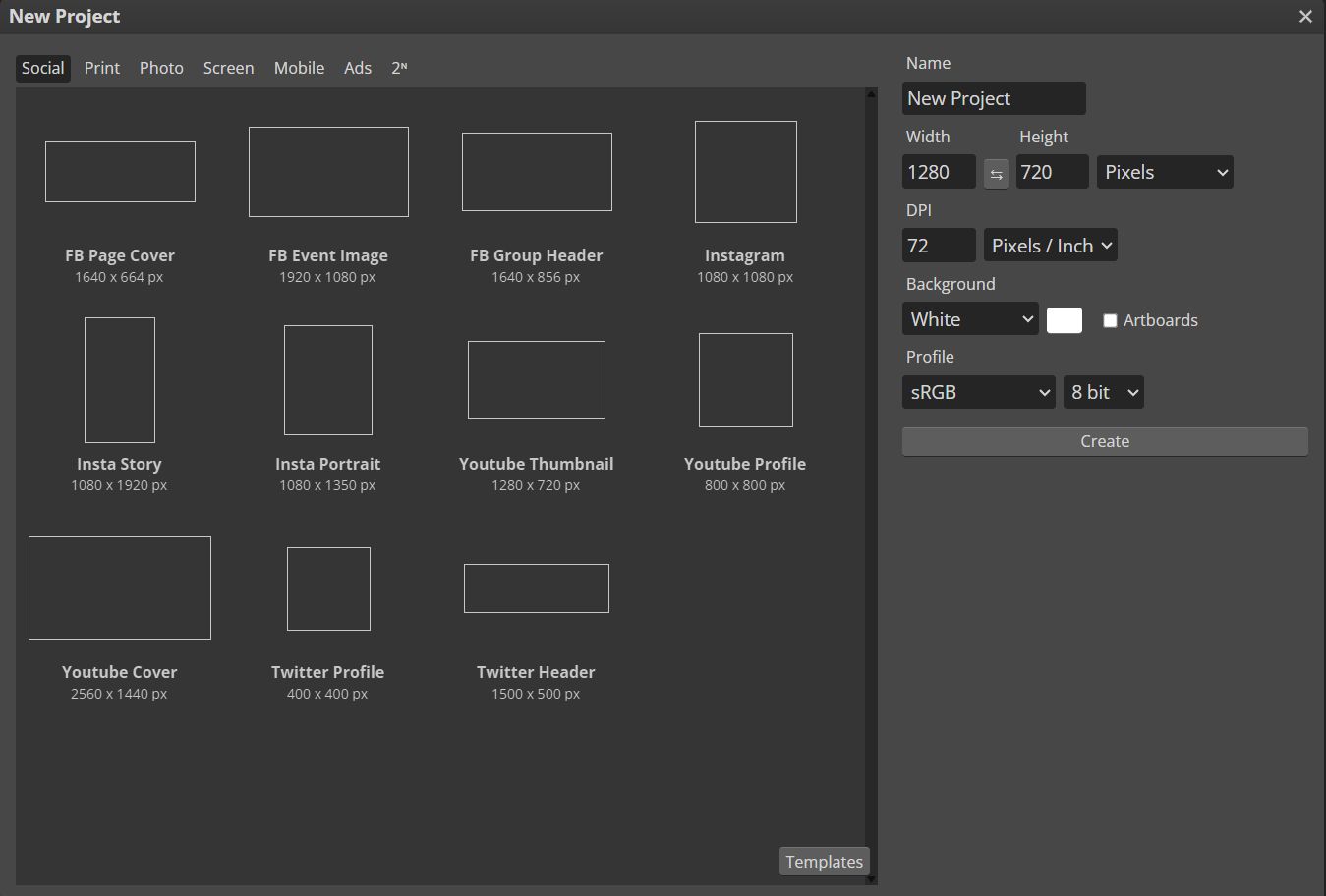
i chose to create a new file. the next page displayed different canvas size with preset layouts as well as editable option.
here i chosed a4 template
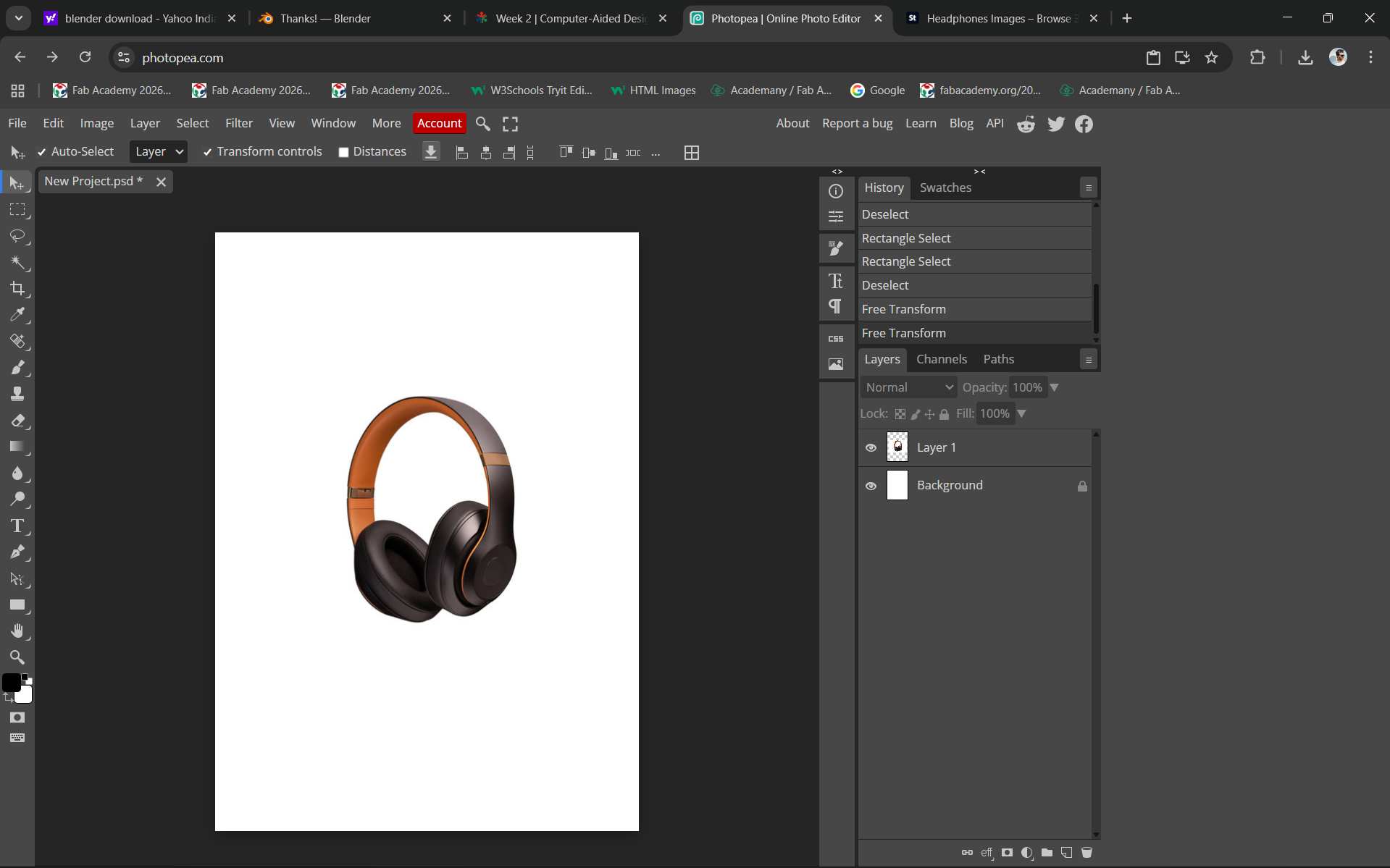
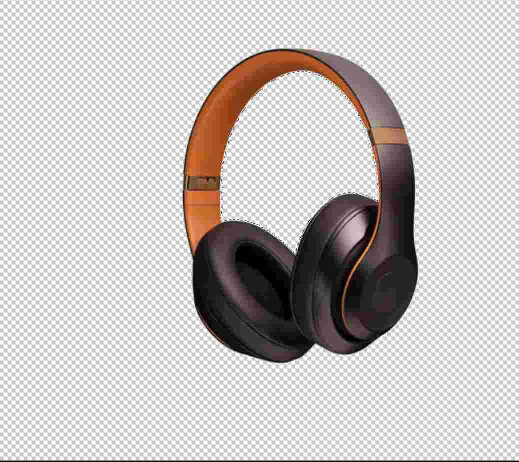
using magic tool i removed backgroud
i took backgroud texture from my galery
Using the text tool, I selected a font that I liked. After that, I copied and pasted the text and arranged the text layers accordingly.
Canva
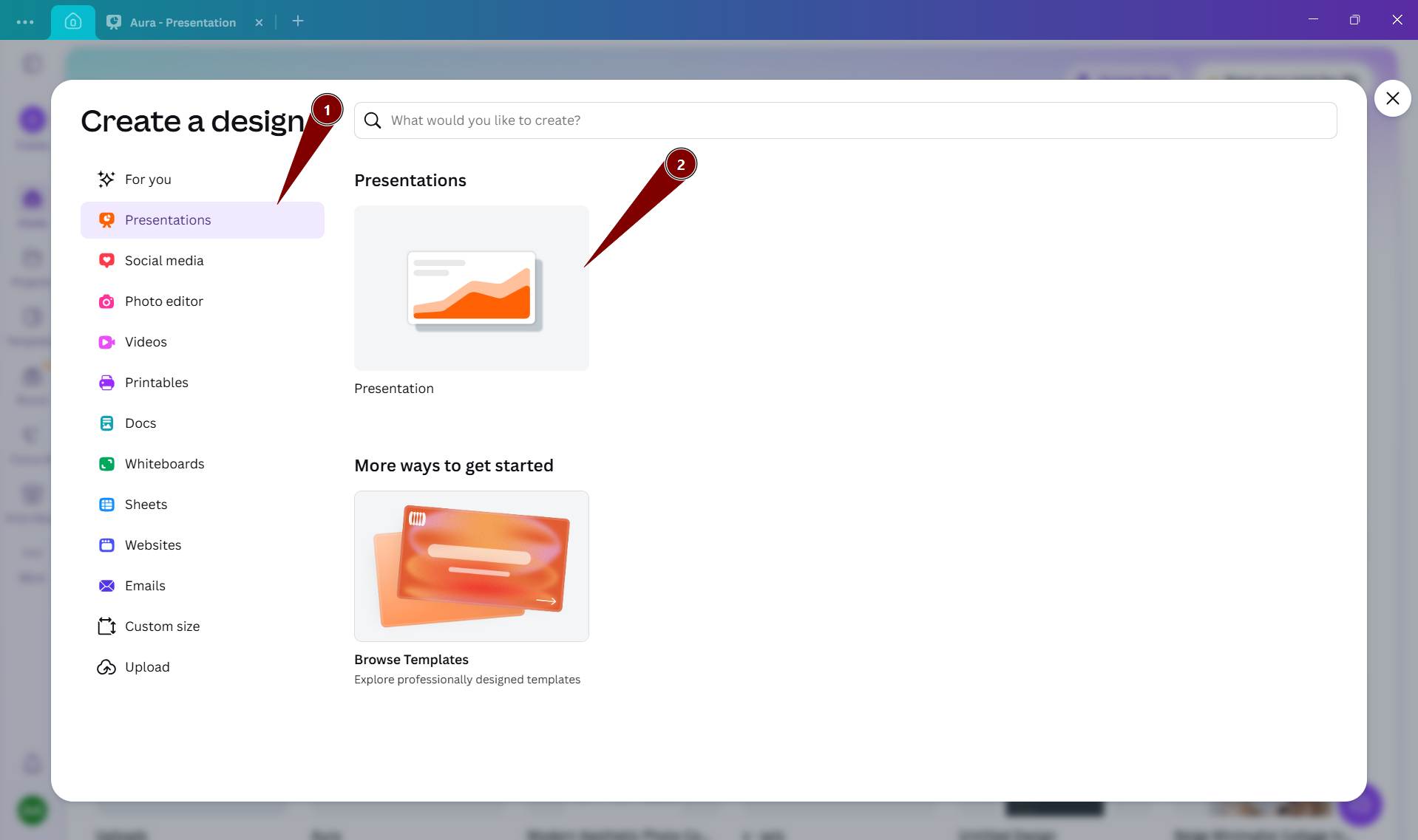
here iam going to try canva its an online design tool iam going to create slide
1st i selected a presentation template
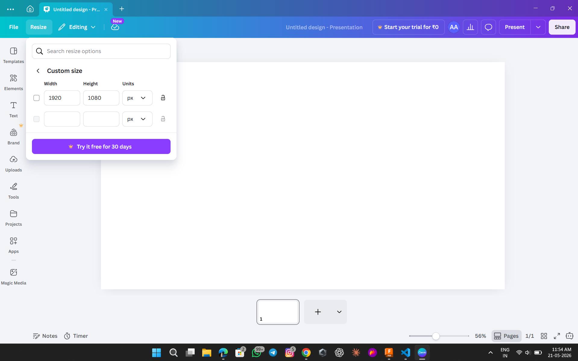
need to select a Ratio of slide
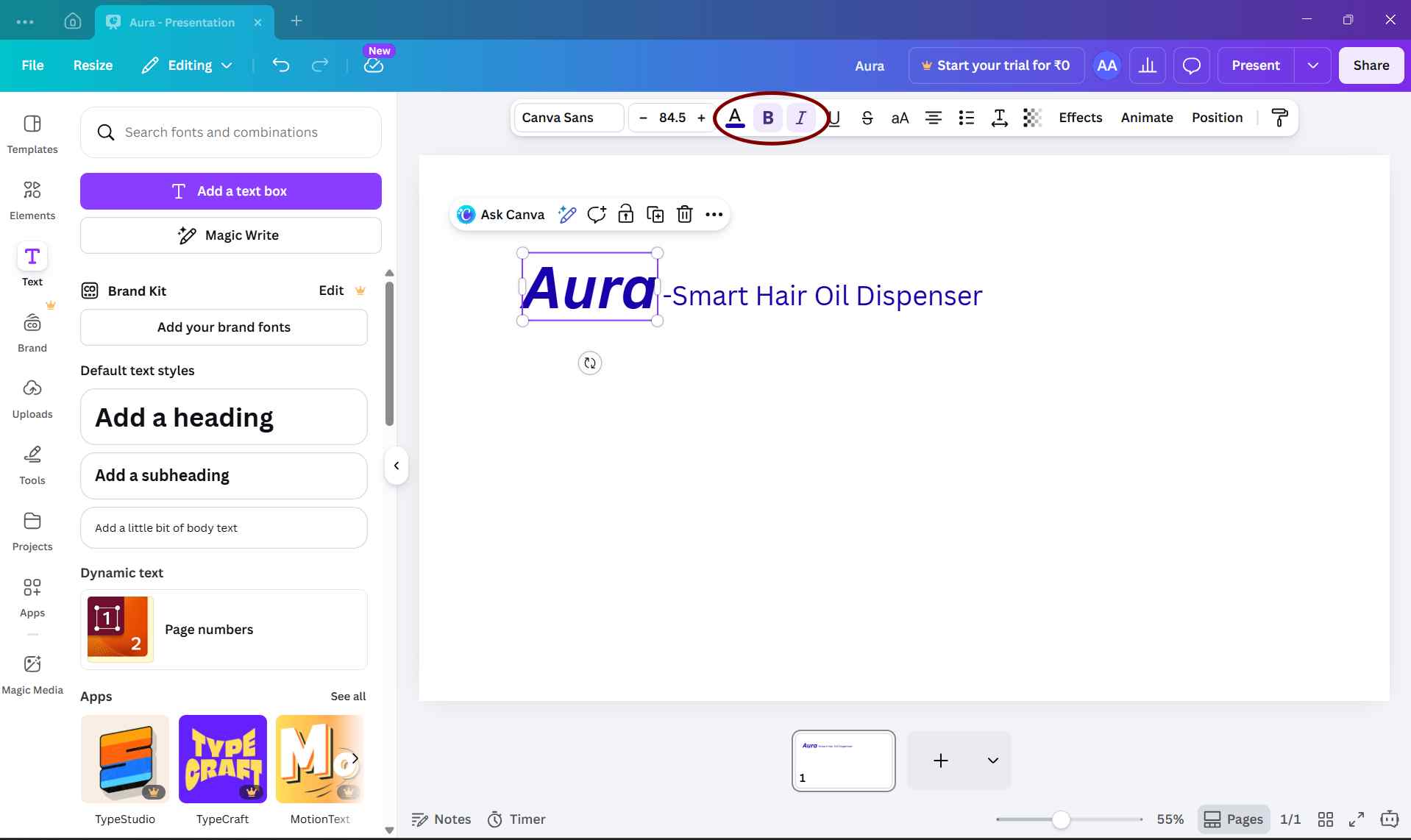
To add heading i select Text heading option
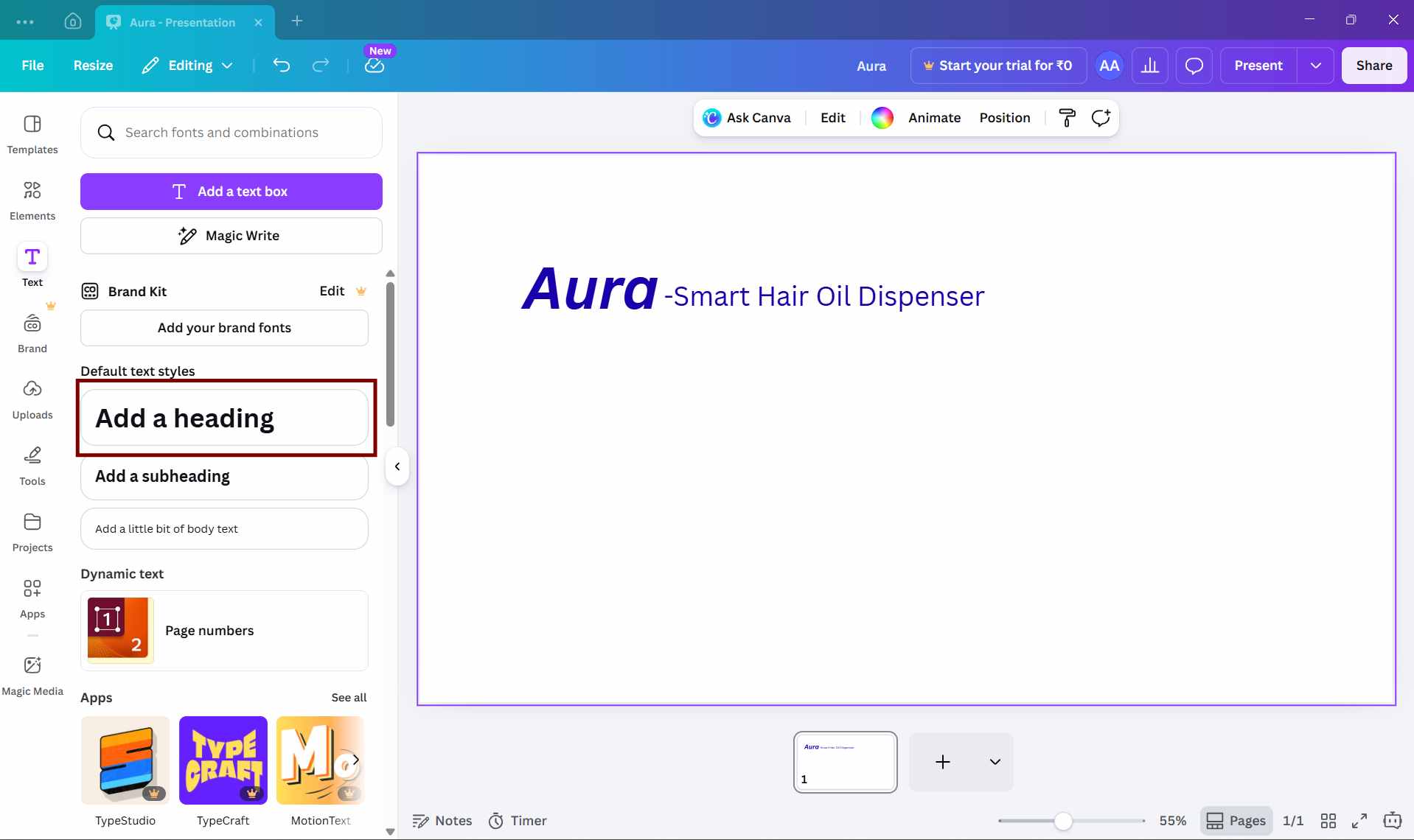
i add colur and font size and bold
i uploaded some images for slide for that i select upload option
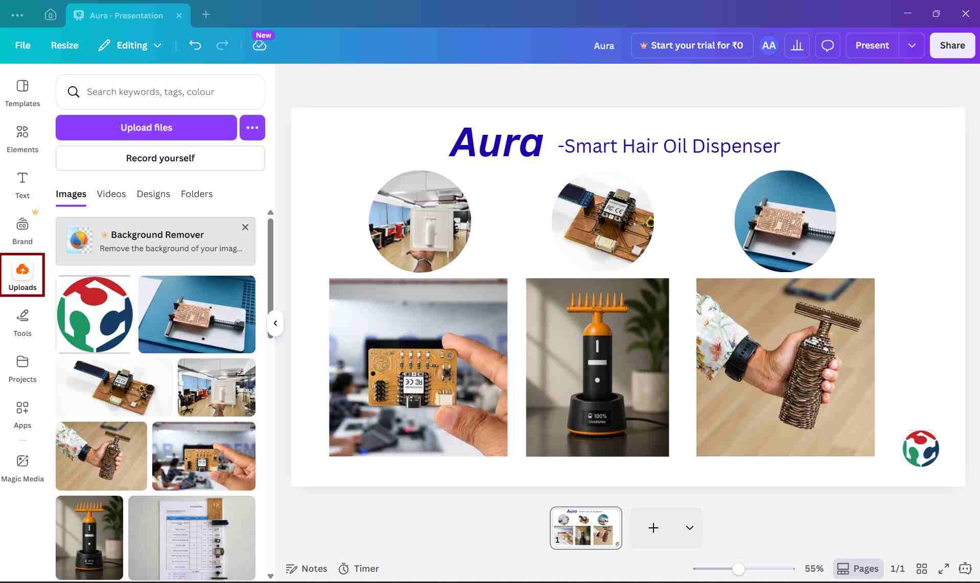
after uploading i added the images to the slide and arranged them accordingly
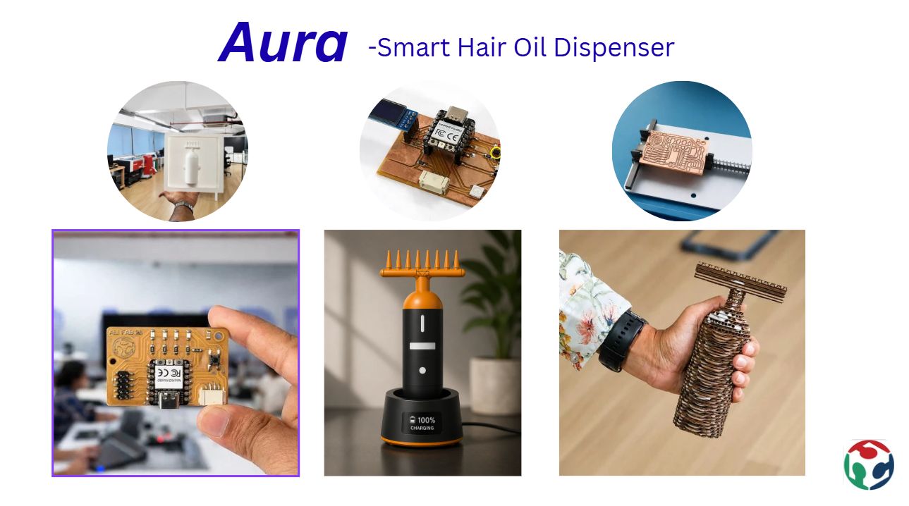
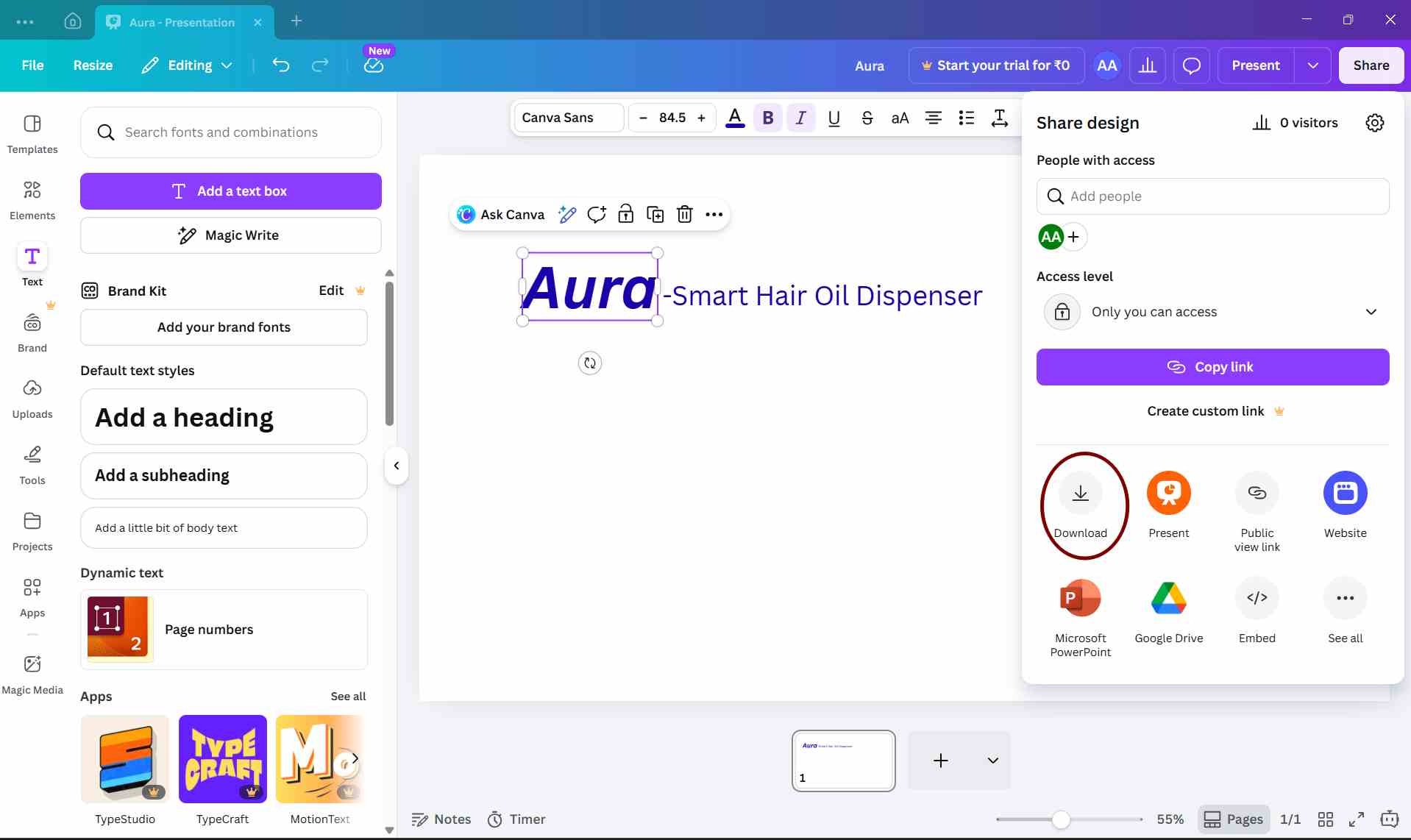
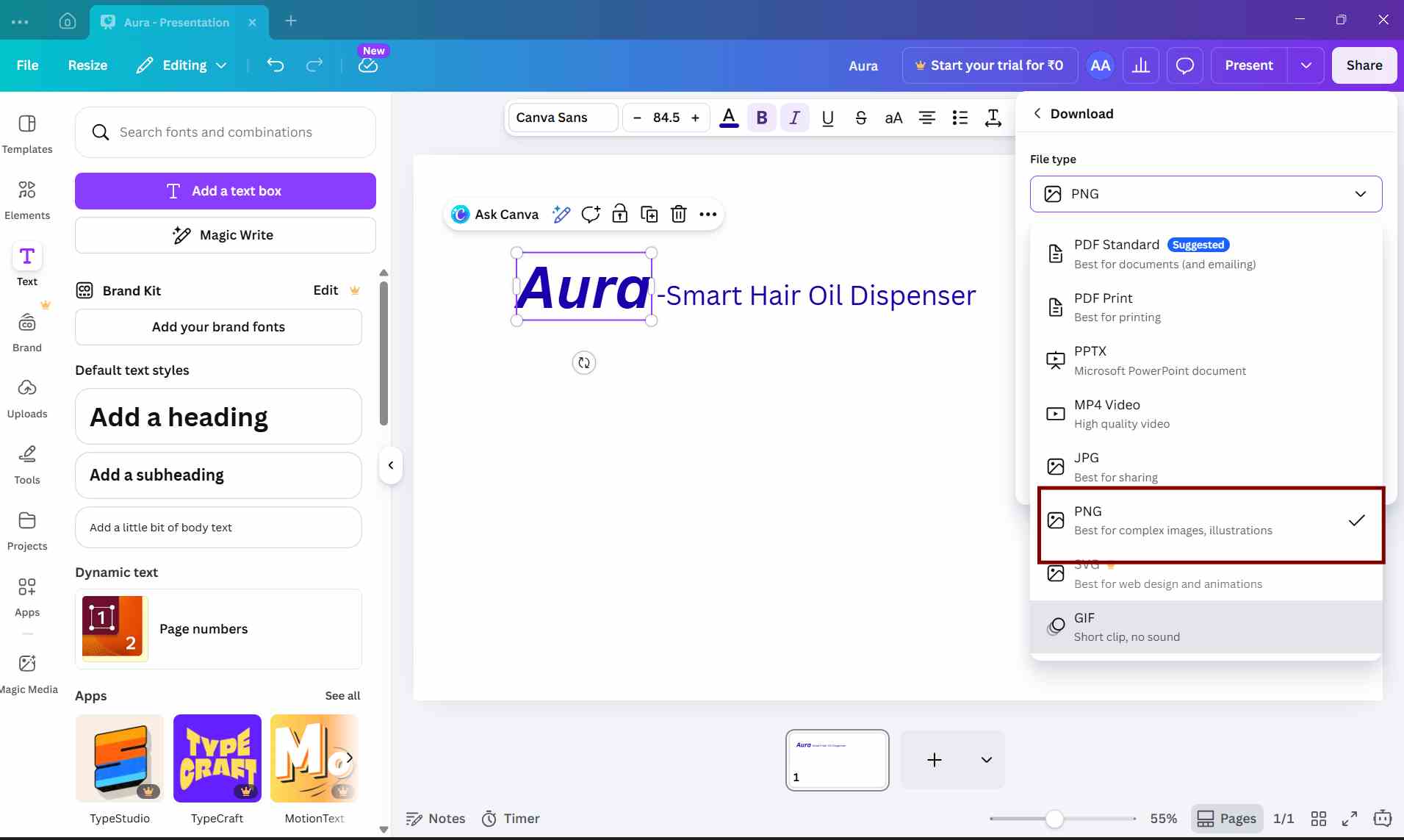
after setting up the slide i downloaded image as png
Understanding 3D Design
Tinker cad
Tinker Cad is a free and open-source software used to create 3D models using code. Instead of drawing shapes manually, designs are made by writing simple commands and parameters. It is mainly used for parametric and precise models, especially for 3D printing and digital fabrication.
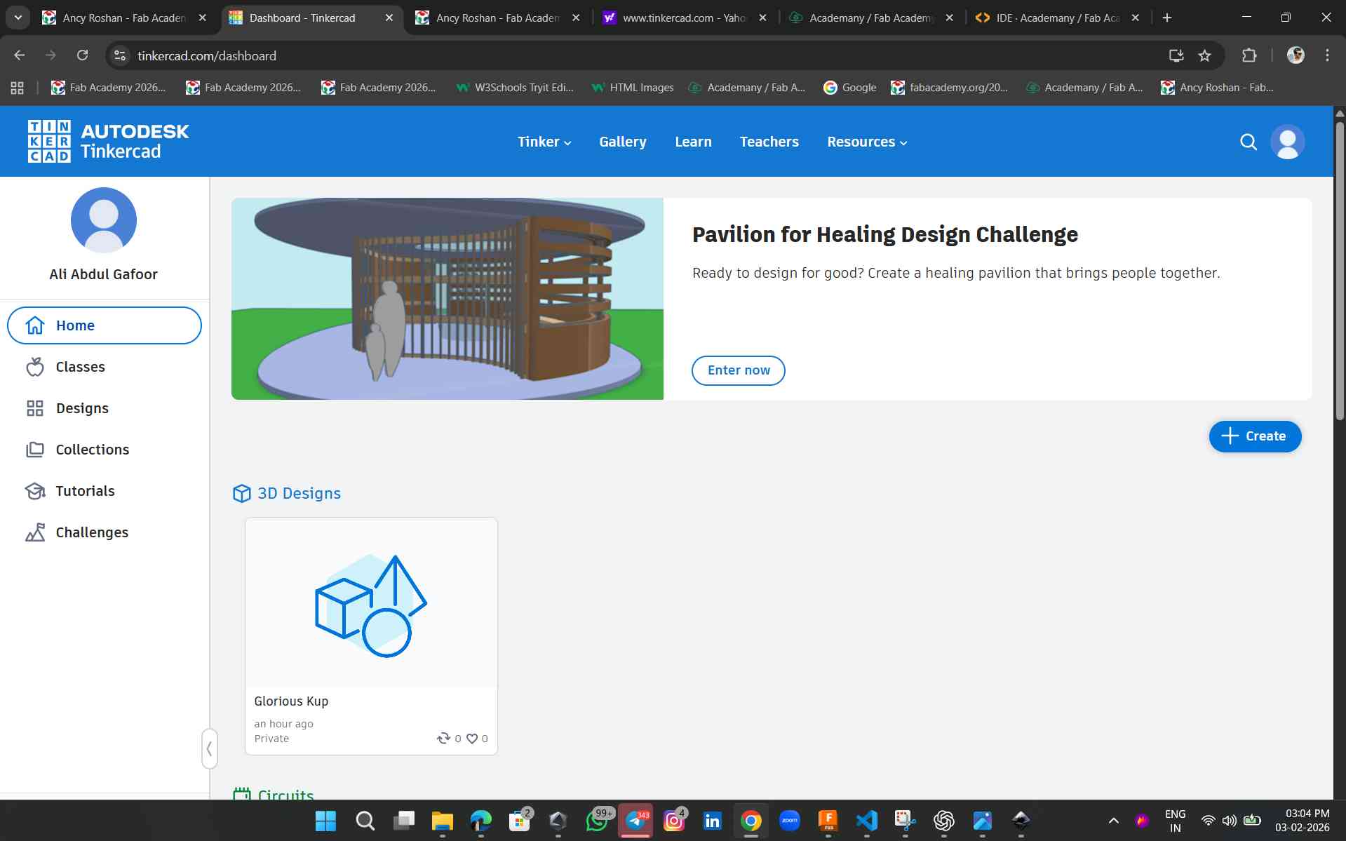 here i created a new page and contrected a plane

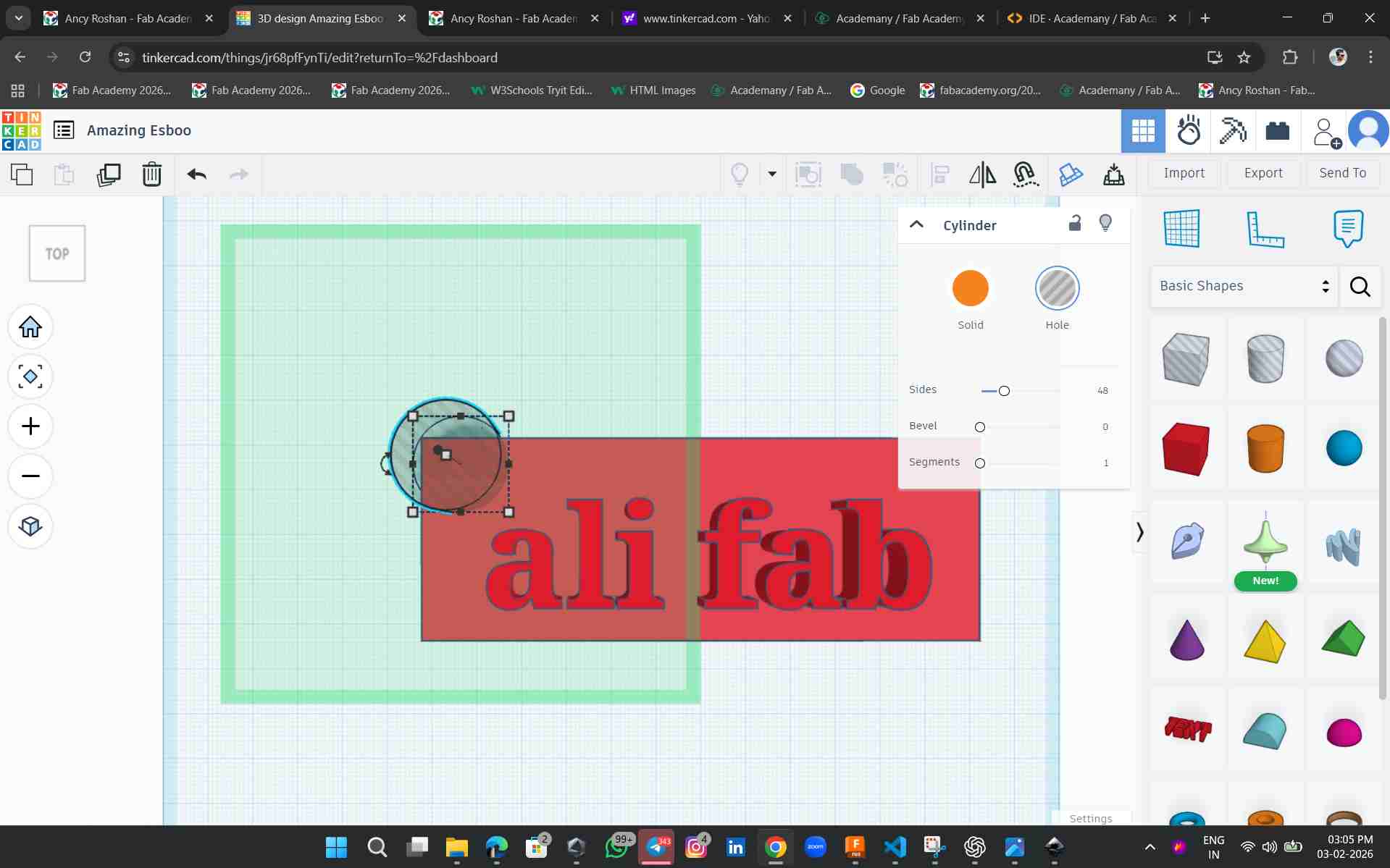
Here, I used a rectangular shape and text to make a keychain. First, I created the rectangle, then added the font text. After that, I extruded both the rectangle and the text to give them thickness.
To add a hole, I used a boolean operation. After that, I used the cut option to remove the required part.
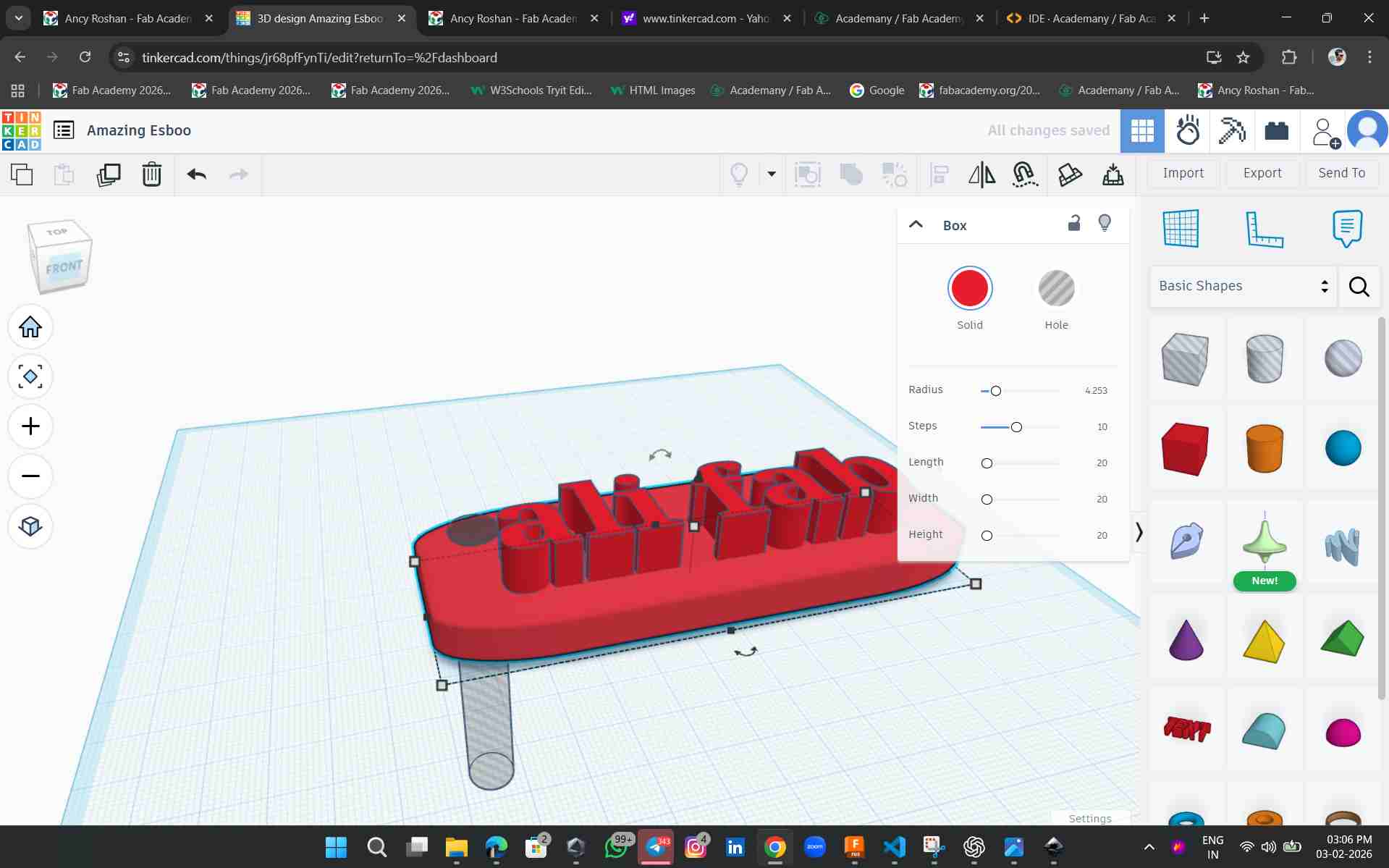
To remove the sharp edges, I used the radius tool.
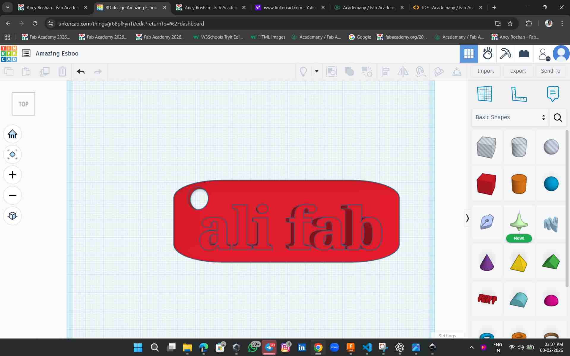
This is my first output using the software, which is a keychain. The software is simple and easy to use, with user-friendly tools.
openSCAD
OpenSCAD is my second 3D modeling software. It is a bit hard for me to understand and use.
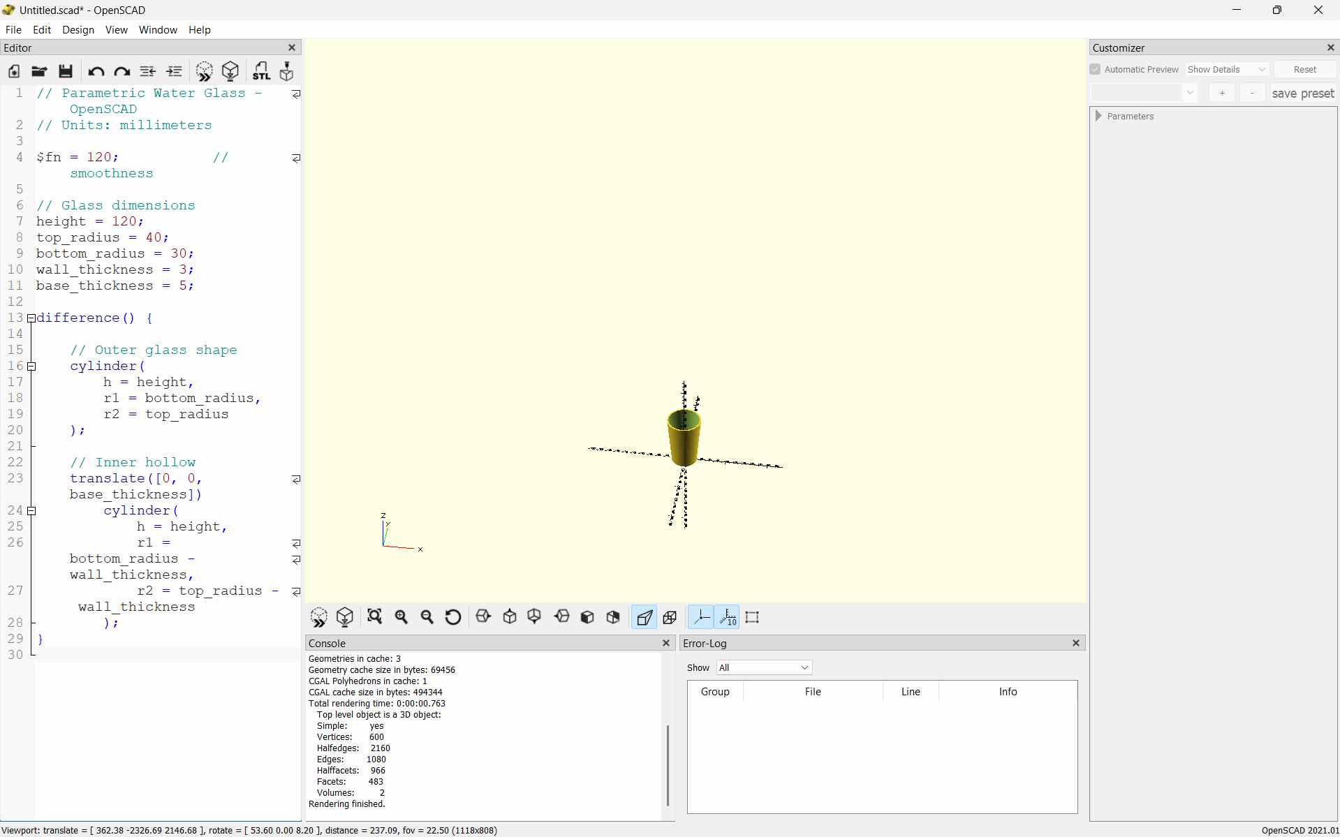
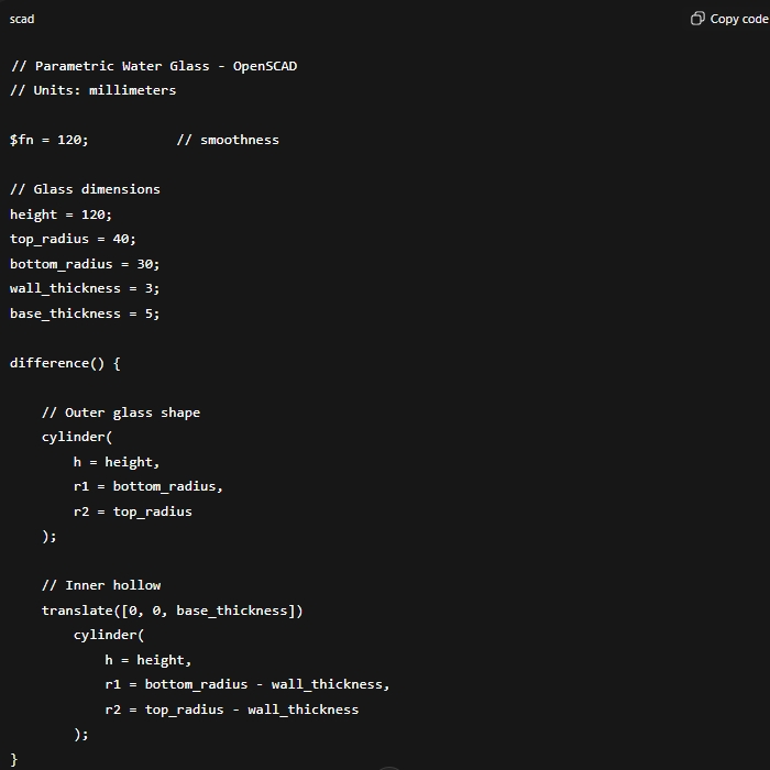
This OpenSCAD code is used to create a parametric water glass. The size of the glass is defined using values like height, top radius, bottom radius, and wall thickness. An outer cylinder creates the main shape, and an inner cylinder is subtracted to make it hollow. By changing the values, the glass size can be easily modified.
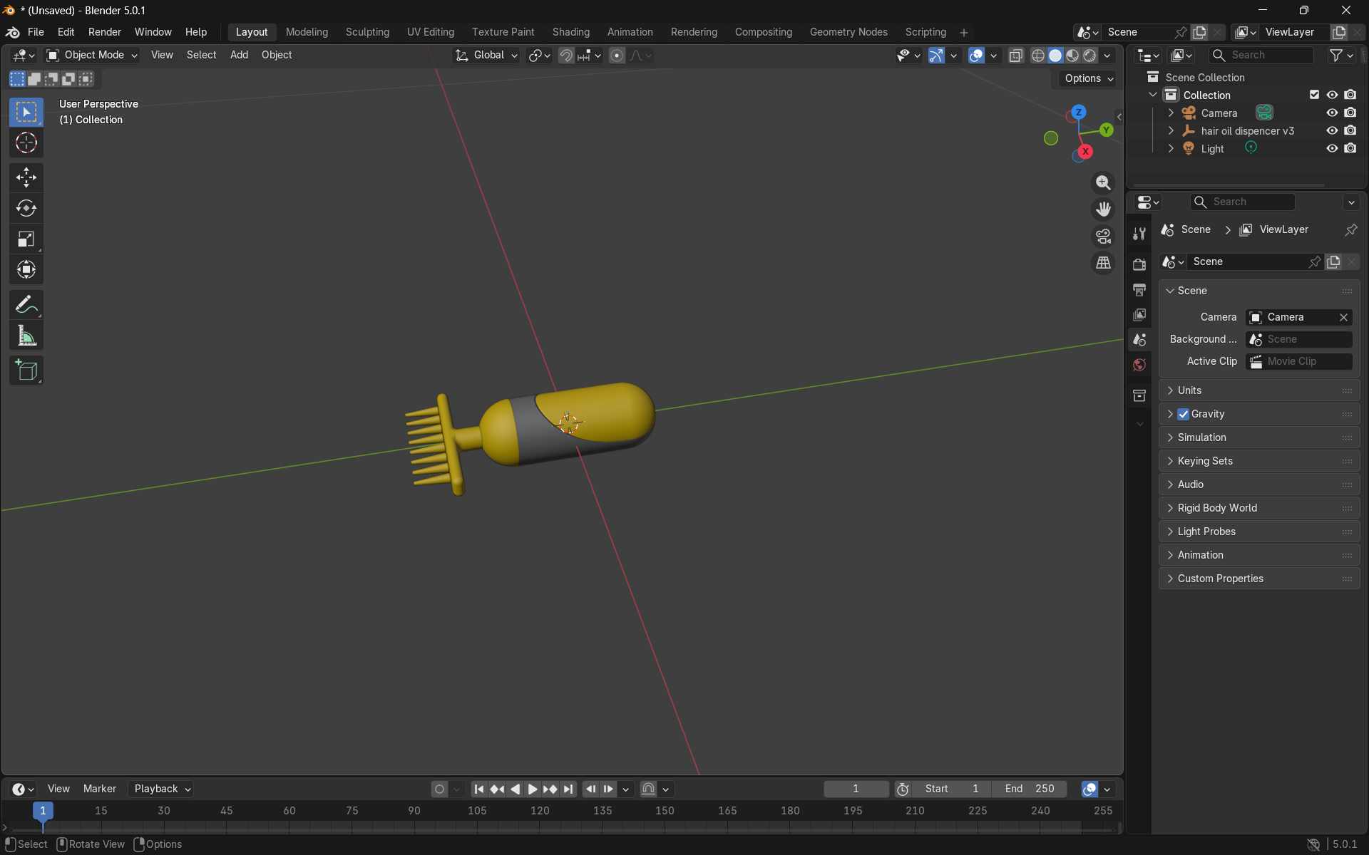
Blender
In Week 02, I used Blender. to understand basic 3D modeling and video animation.I created a simple product model and learned how to make a rotation animation and render it as a video.
Modeled a hair oil dispenser using fusion
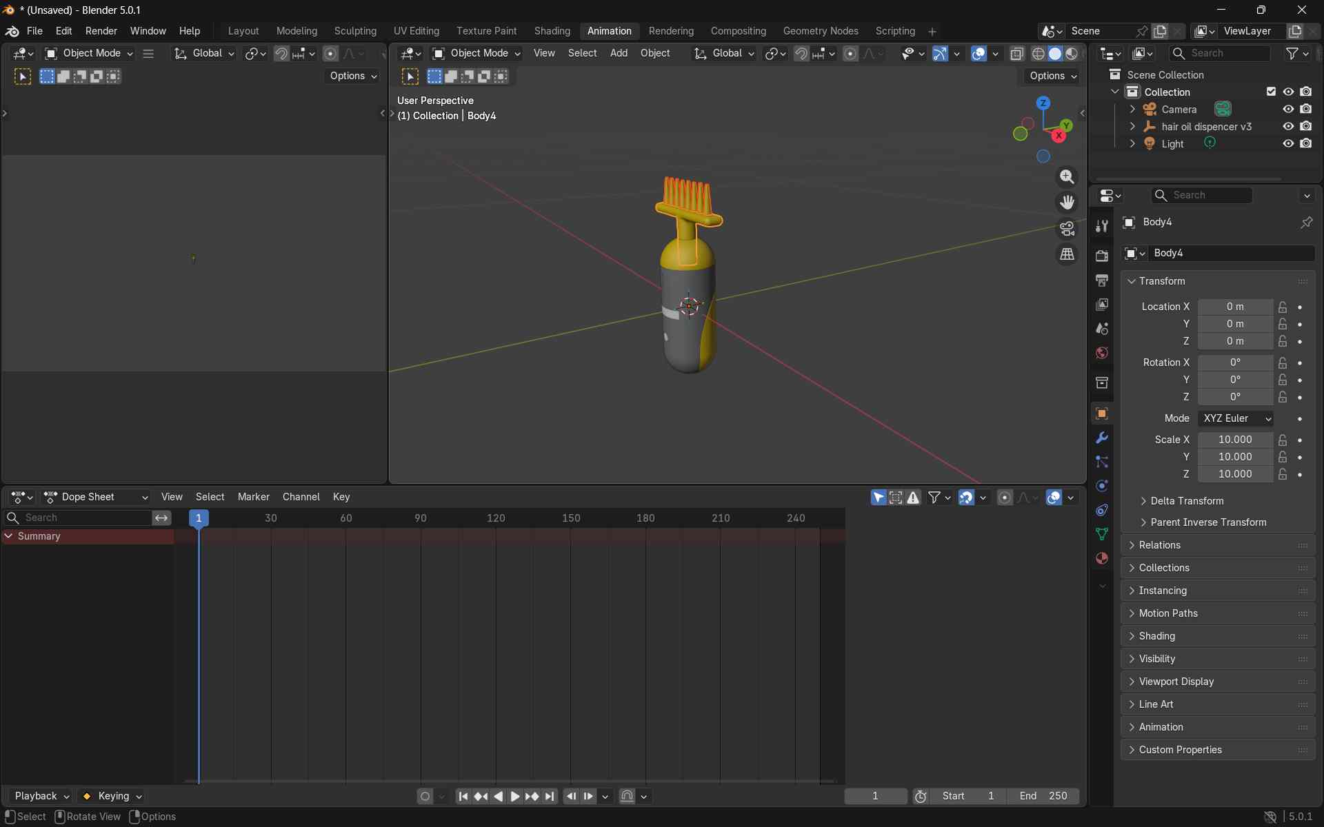
Render Video
Render → Render Animation
In Week 02, I learned many new things using Blender. Personally, I do not prefer Blender for designing models, but I feel it is good for making animations.
Fusion
During this design week, I studied three different software tools. Among them, I am more comfortable with Fusion 360 and also have some previous experience using it. Therefore, I preferred Fusion 360 for completing this week’s work.
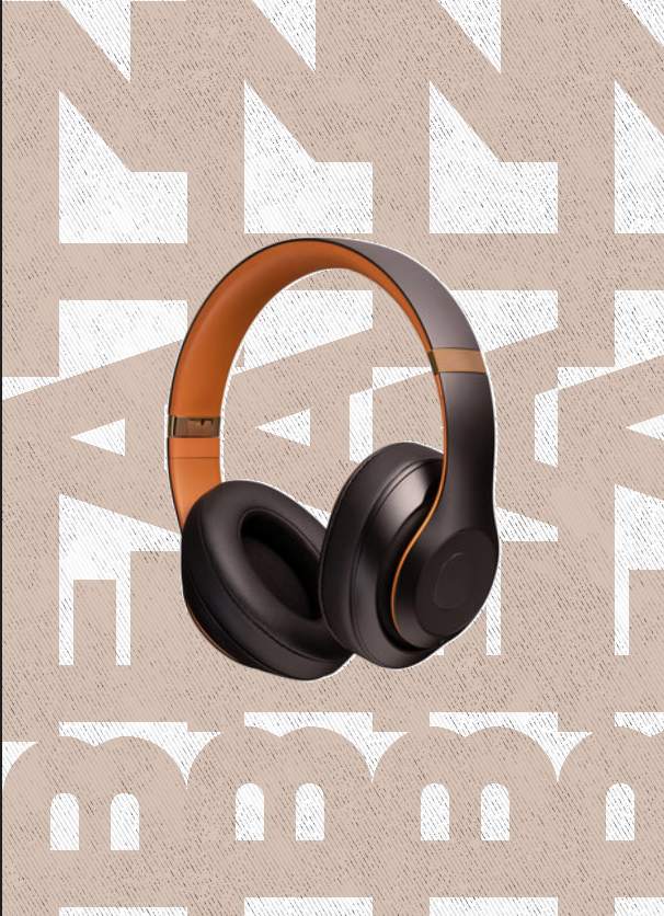
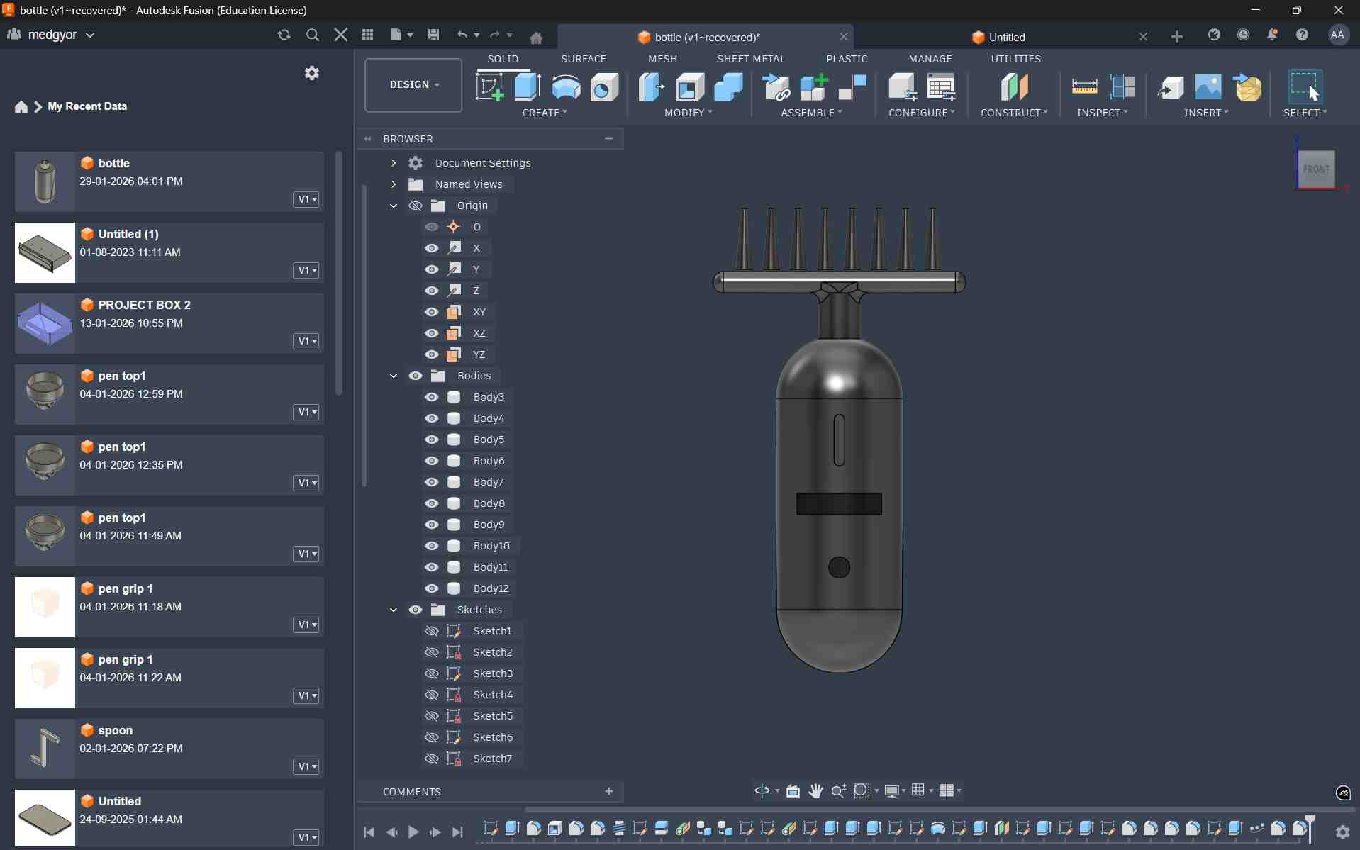
I proceeded to create a 3D model of my proposed final project, the hair oil dispenser, applying the tools and techniques learned during the exercise.
Designing
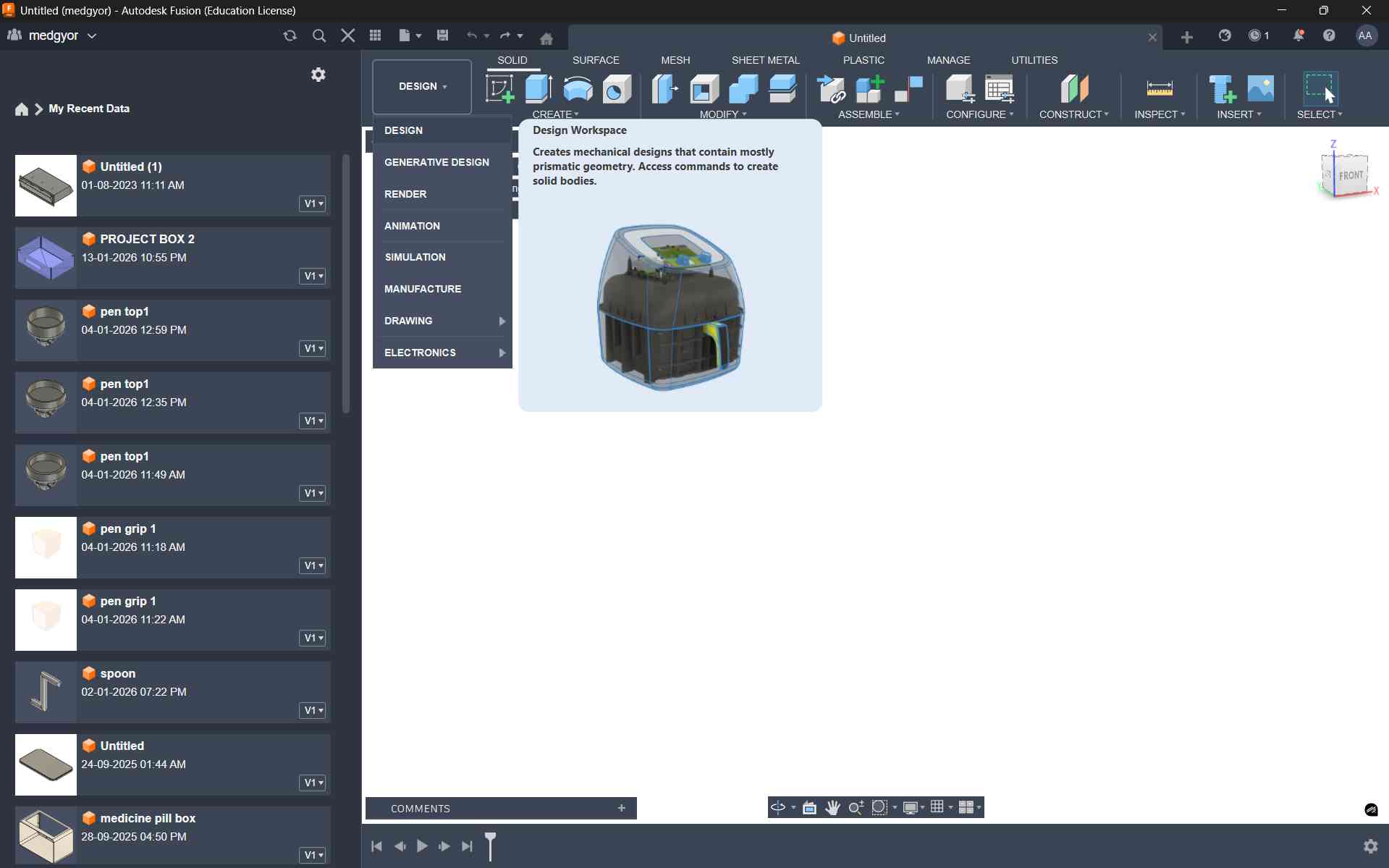
To create a 3D model in Fusion 360, we need to select the Design option from the workspace toolbar.
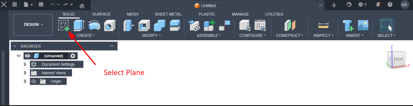
After selecting the Design option, we need to select the Sketch option from the toolbar to create coordinates and start designing.
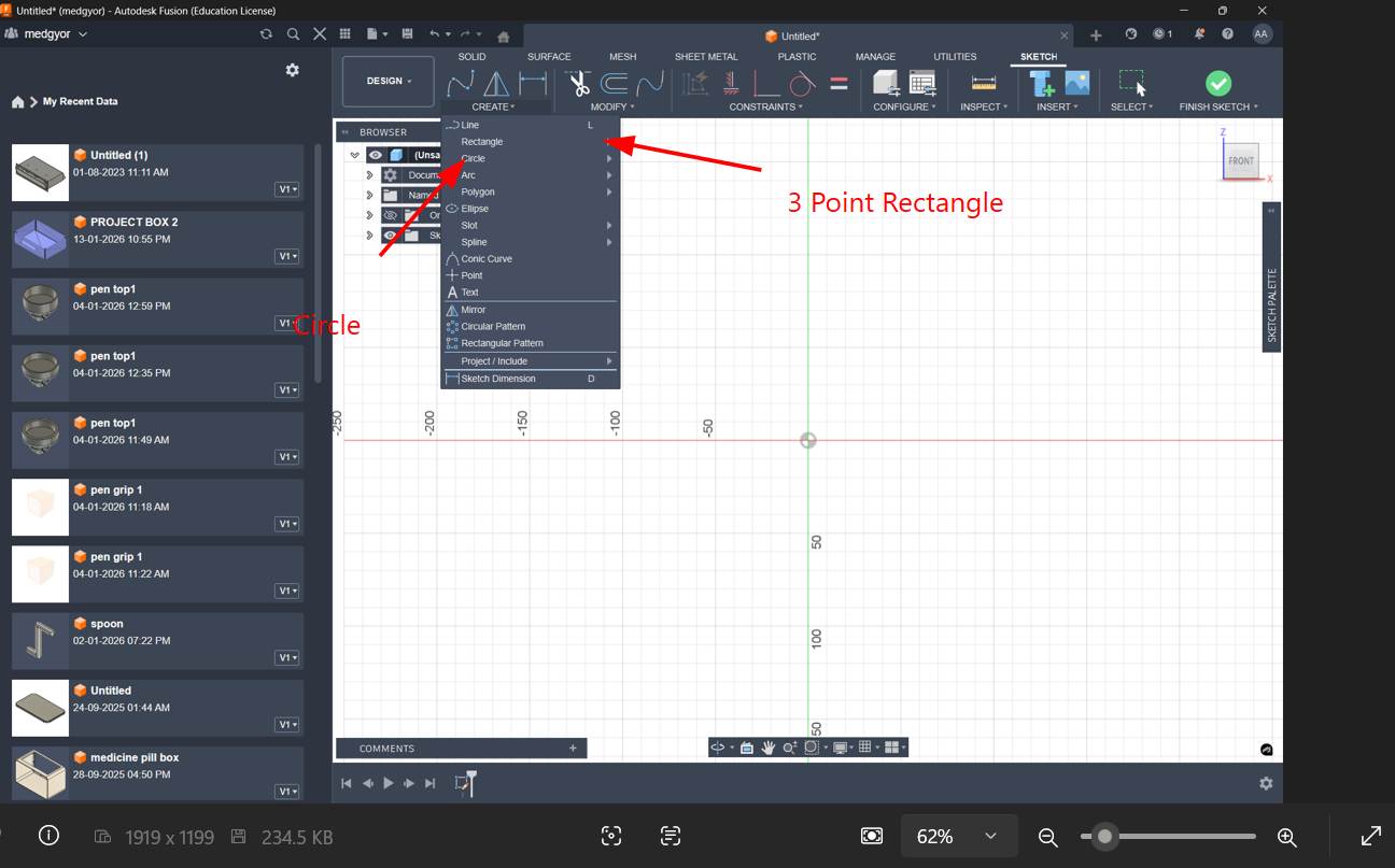
From the toolbar, I selected the 3-point rectangle and center circle tools to create the 2D design.
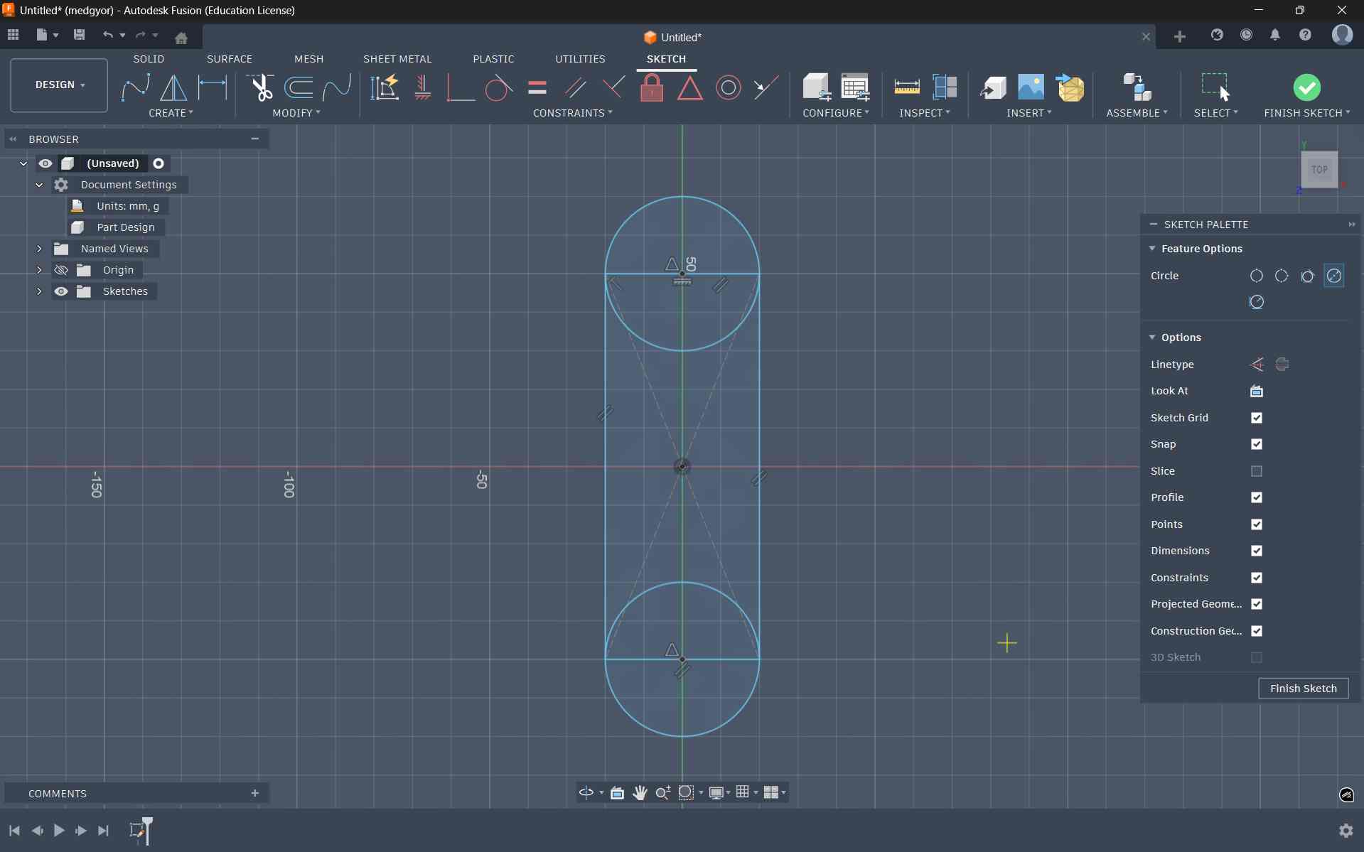
Using the 3-point rectangle and center circle, I created a shape that looks like a cylindrical pill with half circles on both sides.
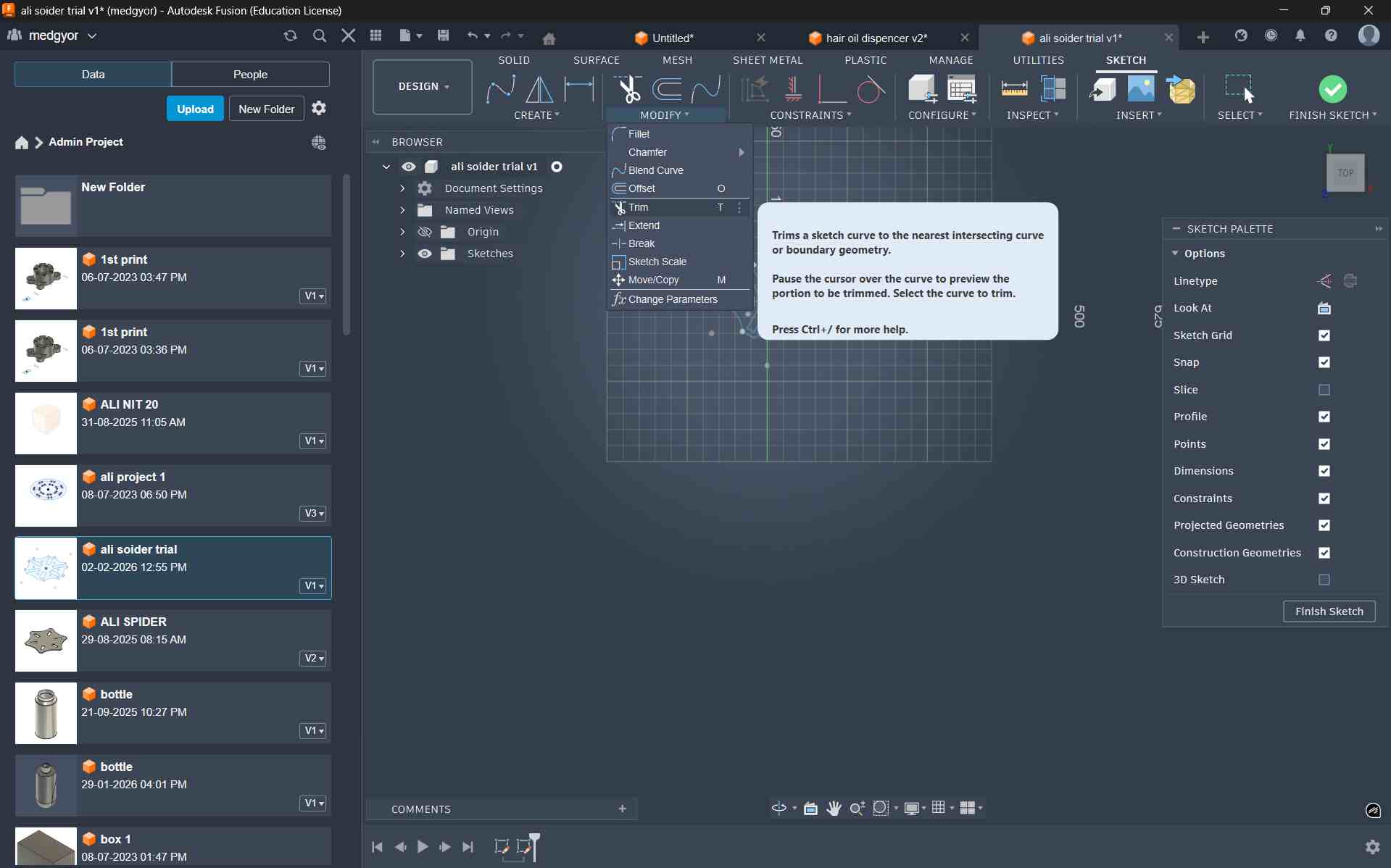
With the help of the Trim tool from the toolbar, I removed extra and unwanted lines. It is very useful.
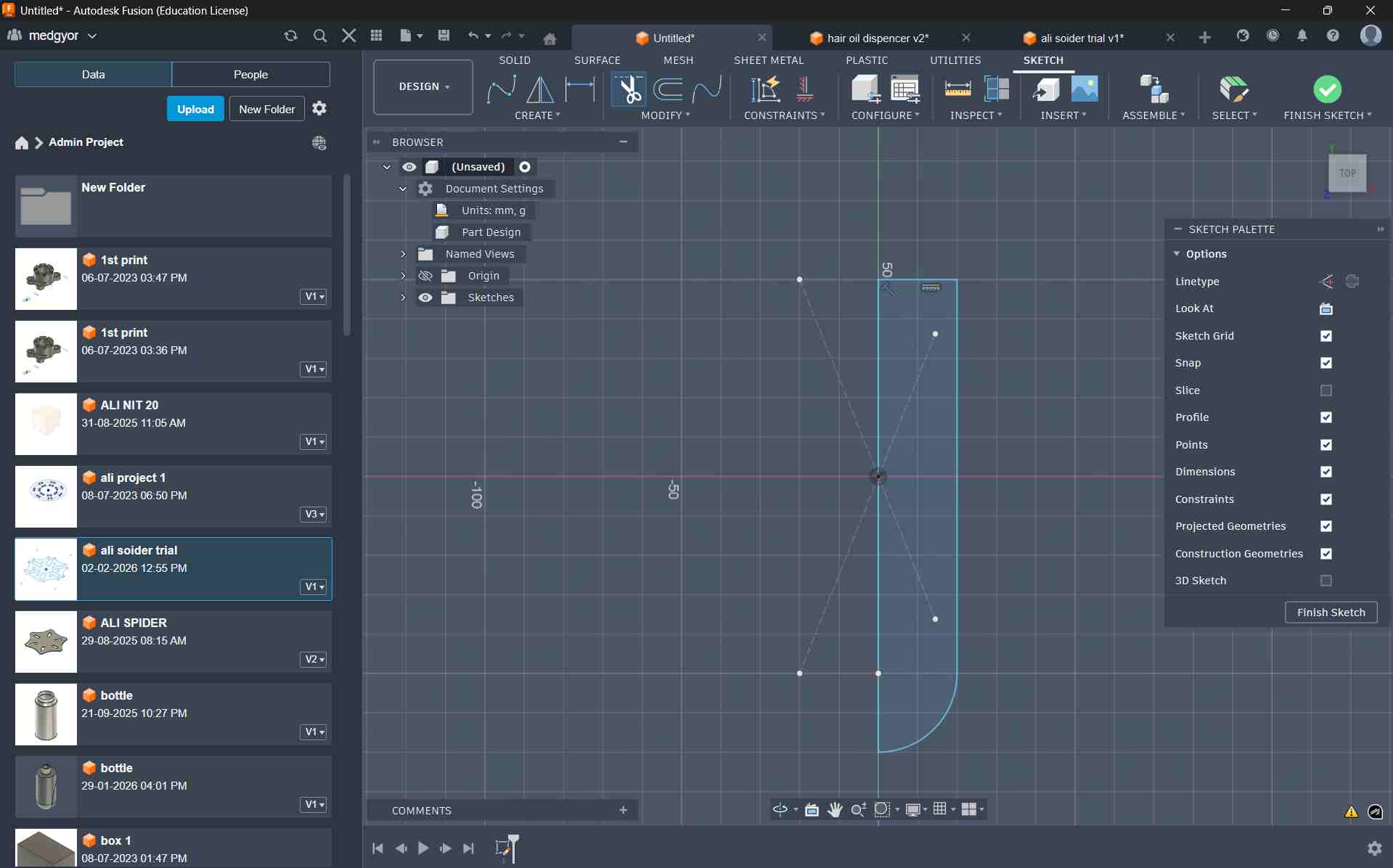
This is the final sketch after using the Trim tool.
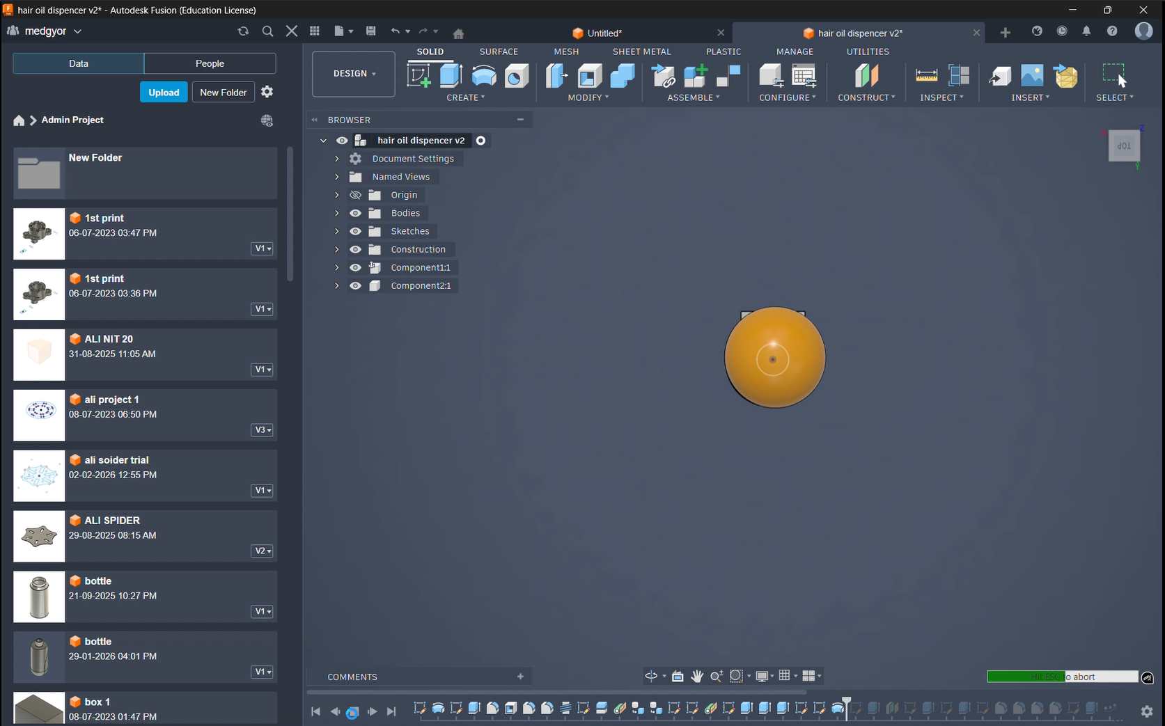
Using the Revolve tool, I converted my 2D sketch into a 3D model.
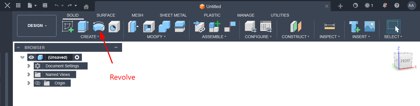
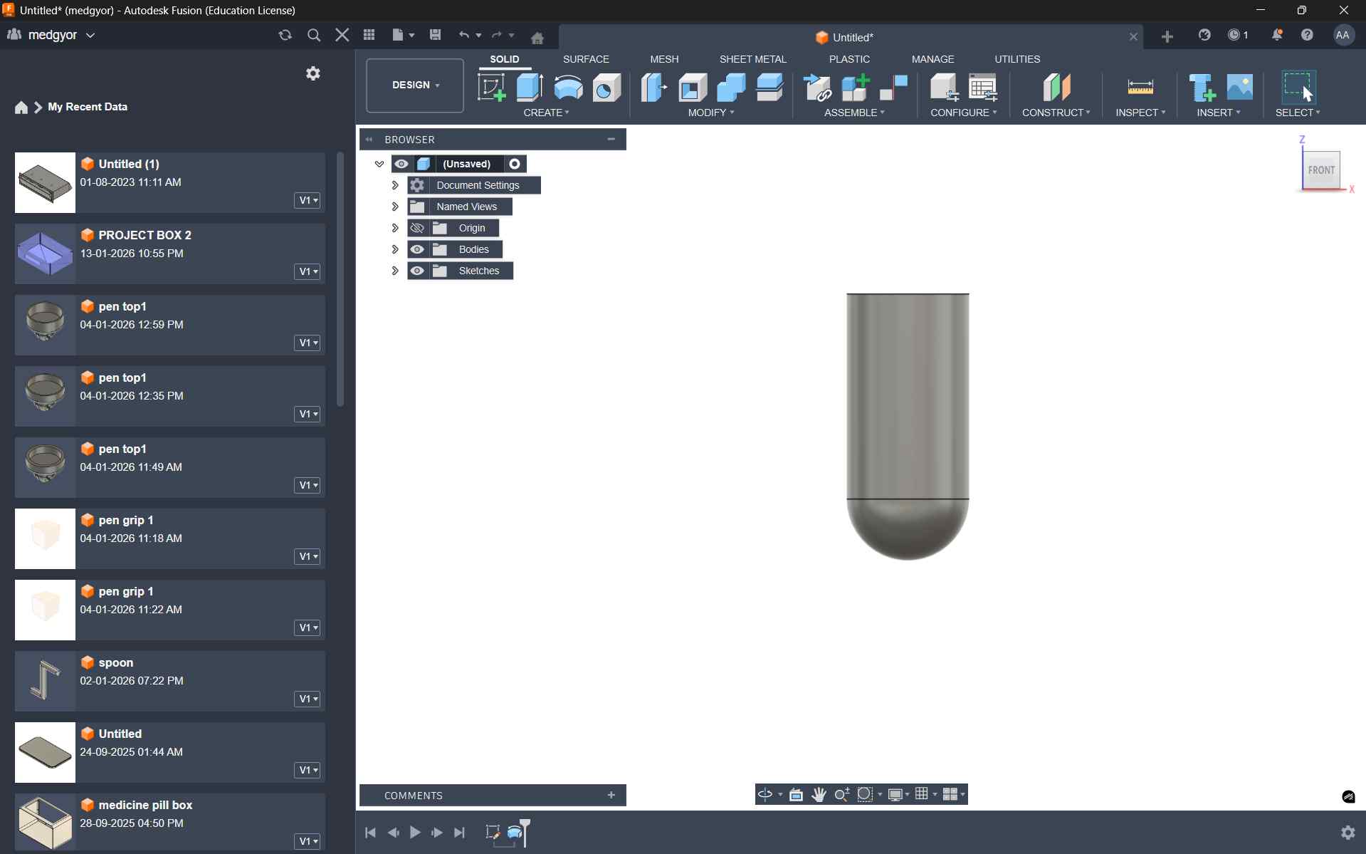
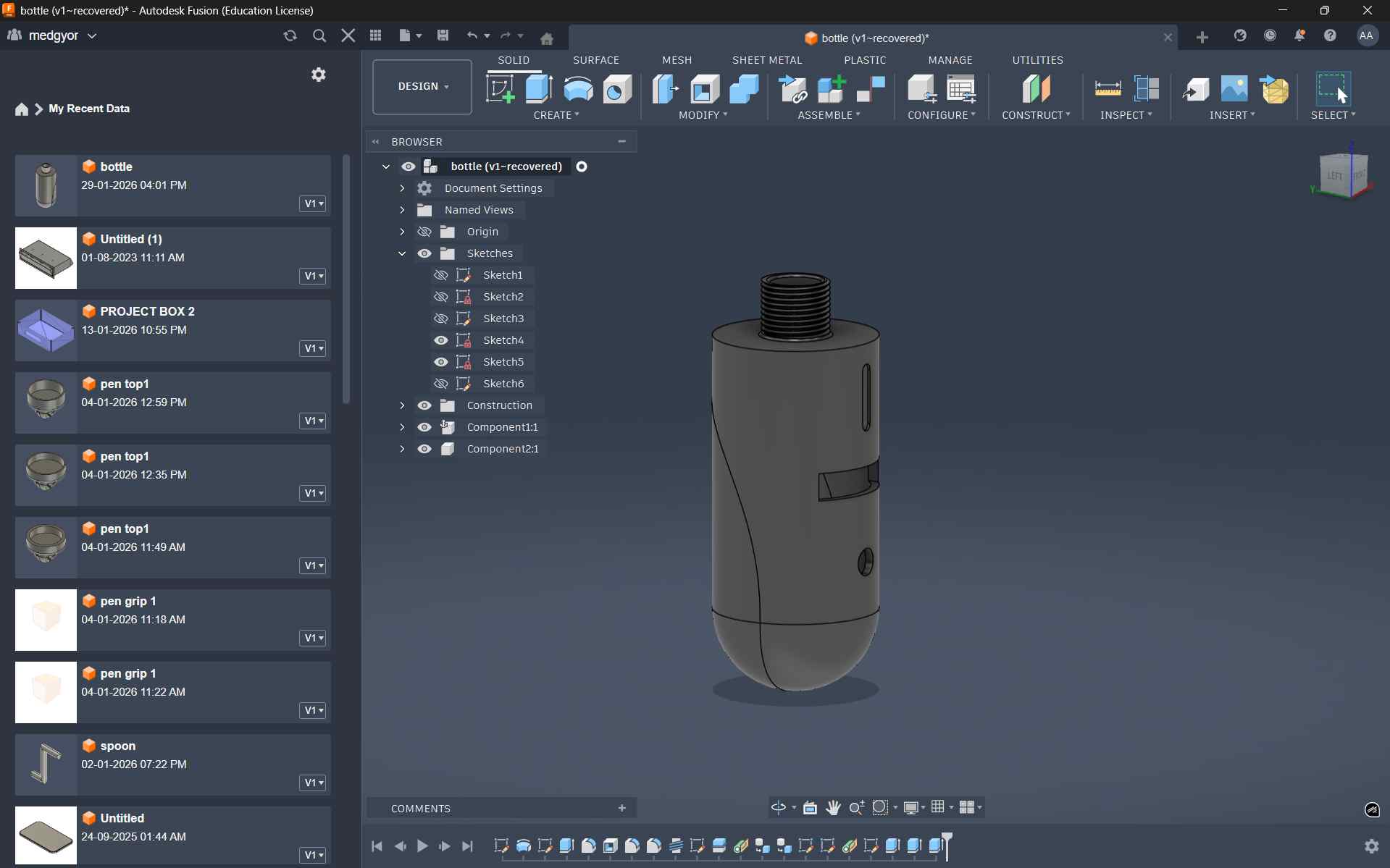
This is the final 3D shape after revolving the sketch.
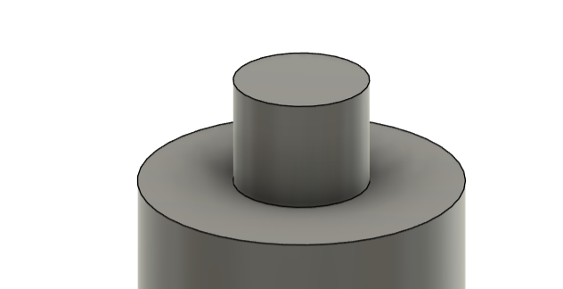
After selecting the Top Plane, I created a small cylinder to form the bottle thread.
To make the bottle thread, I created a sketch on the top of the bottle. Then I drew a circle and used the Extrude option to create the thread.
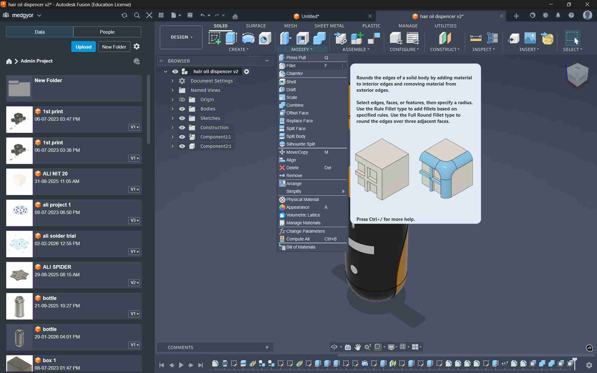
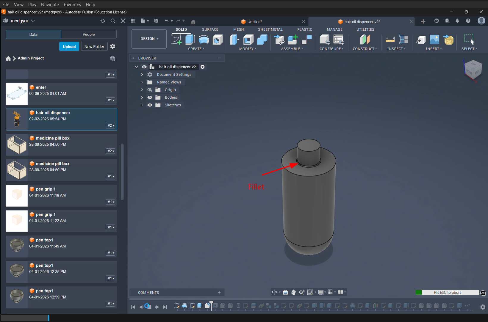
To get a better grip between the bottle and the thread, I used the Fillet tool.
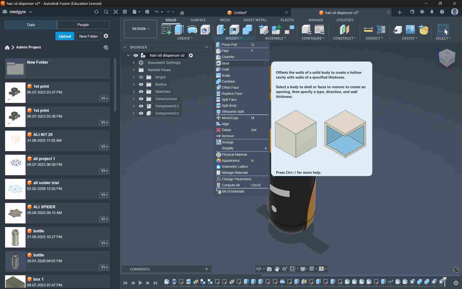
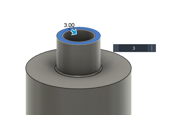
To make the inside hollow and give it a bottle effect, I used the Shell option.
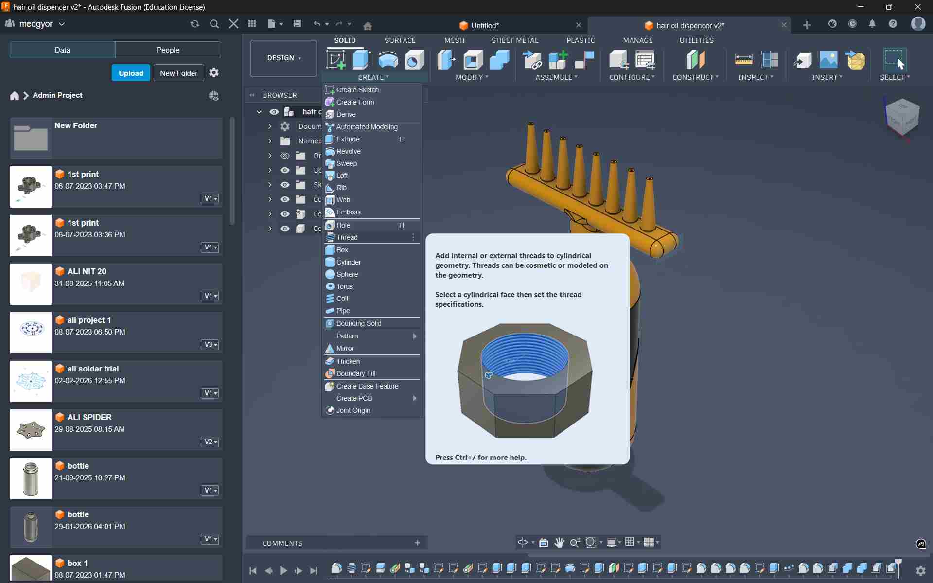
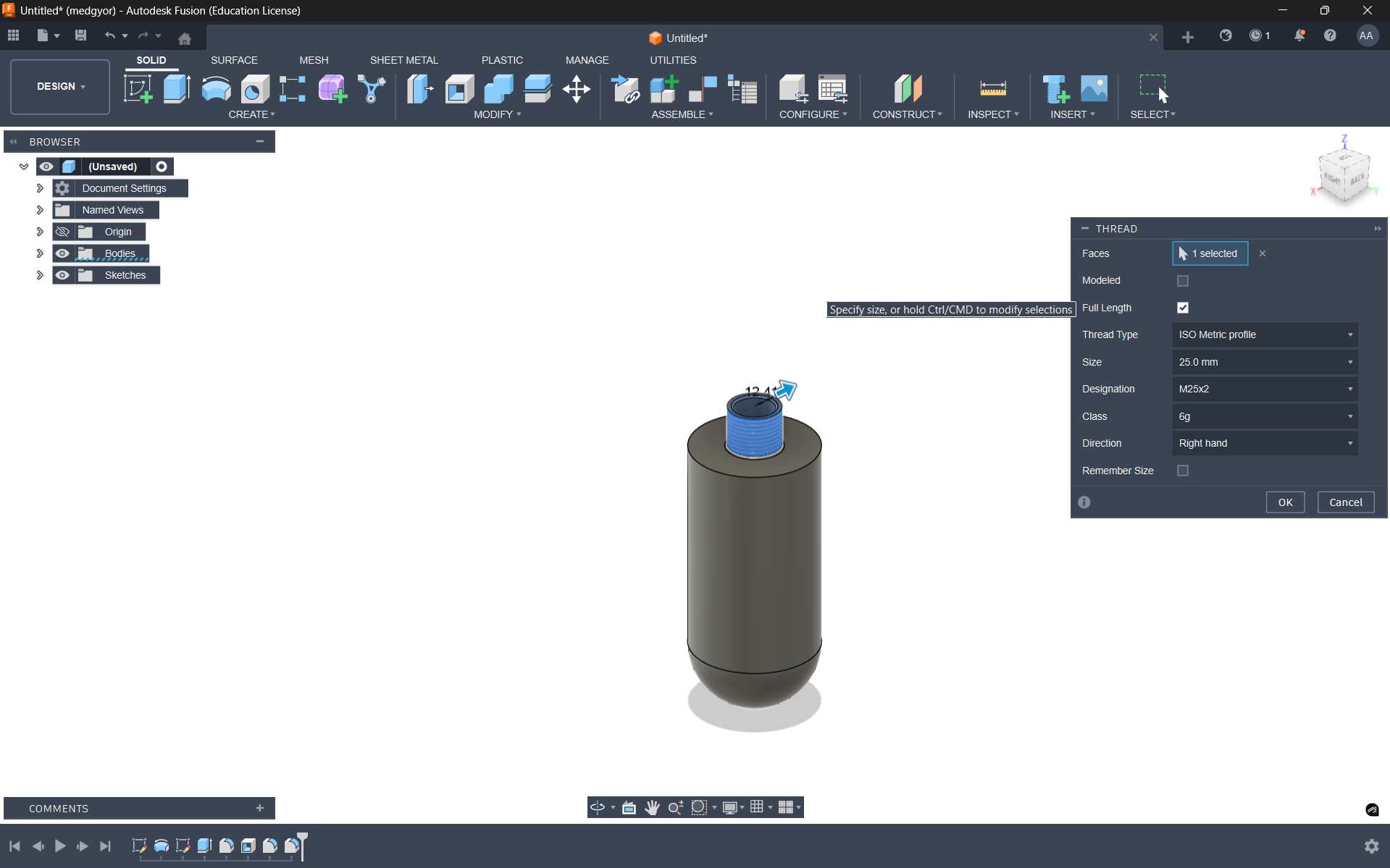
To add the bottle cap, I used the Thread option.
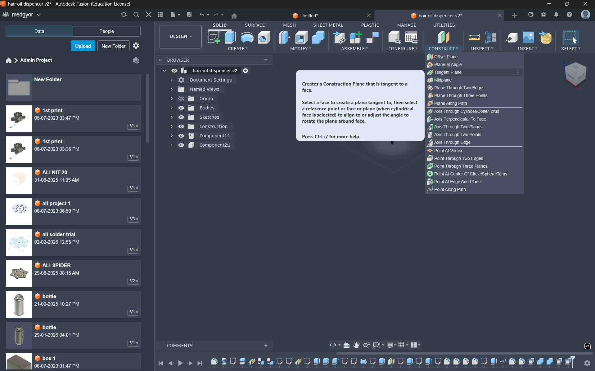
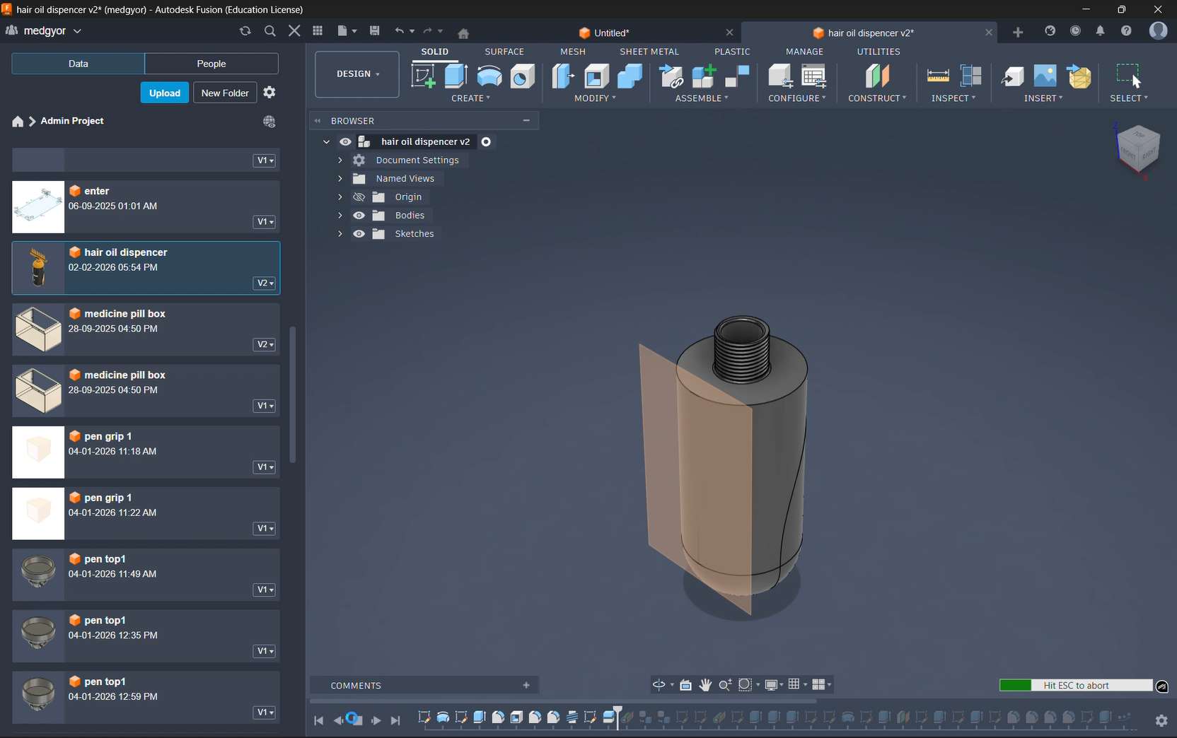
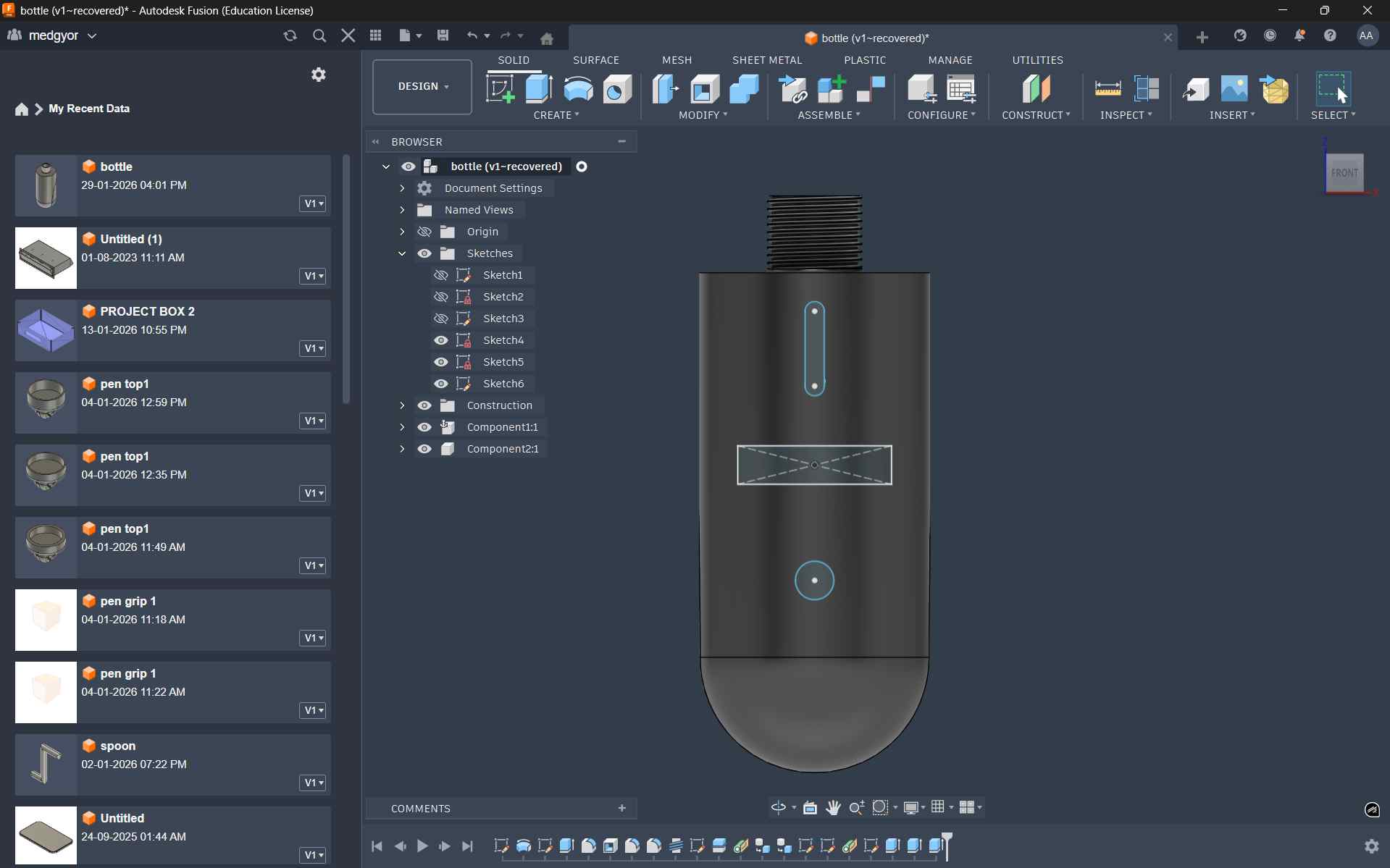
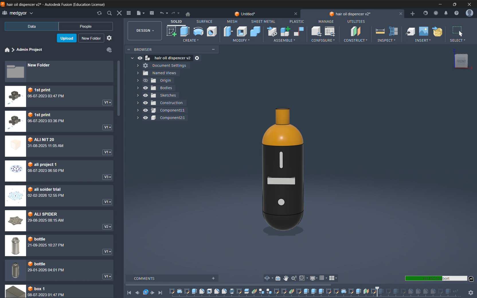
We cannot create features on a curved surface directly, so I used a Tangent Plane to design the indicators, switch, and display.
After sketching on the tangent plane, I used a Boolean Cut to attach the components.
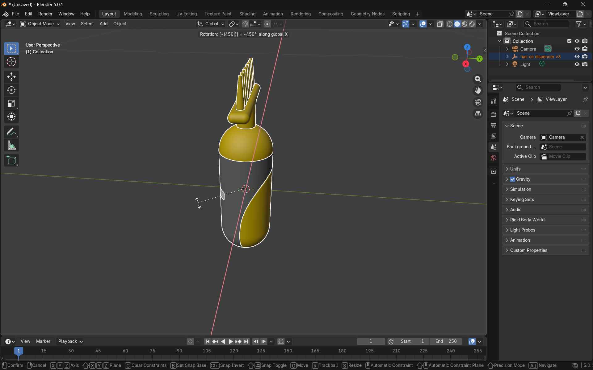
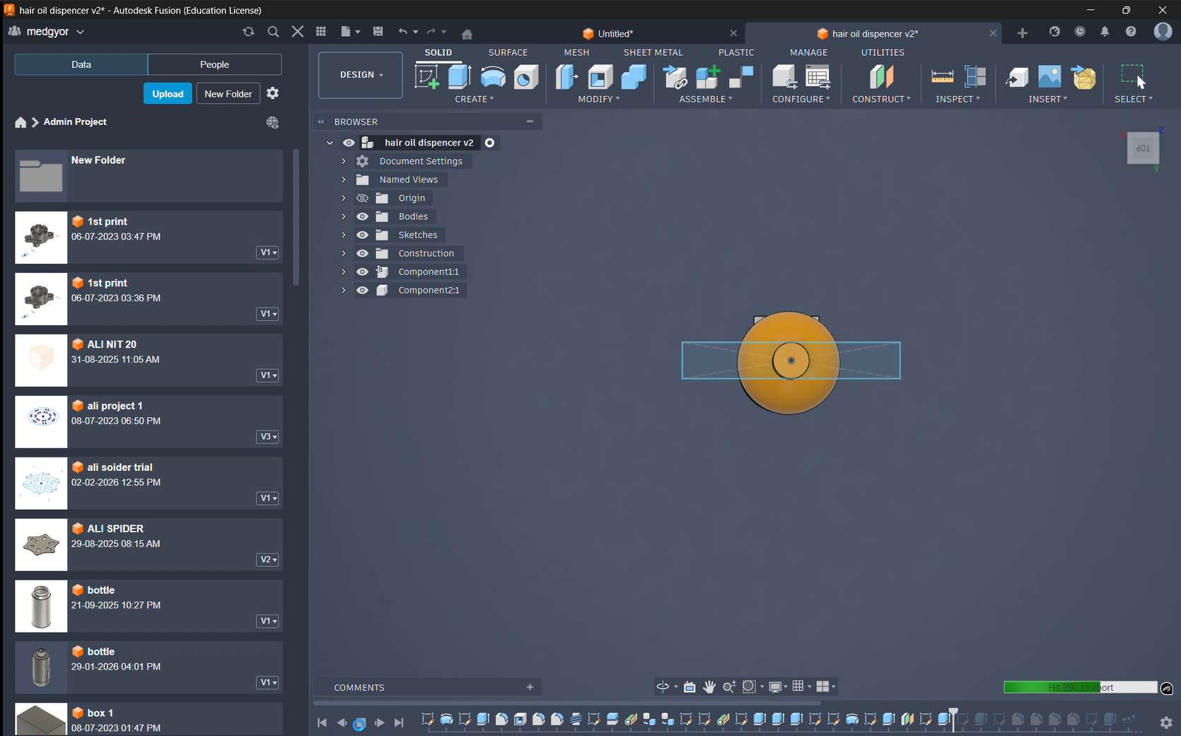
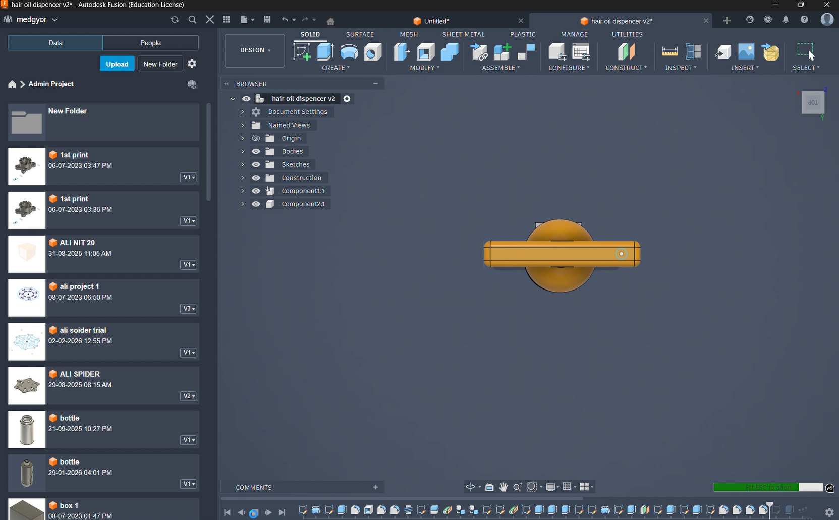
To make the top bottle cap with the dispenser and massager, I drew a semicircle and used the Revolve tool to create the 3D shape.
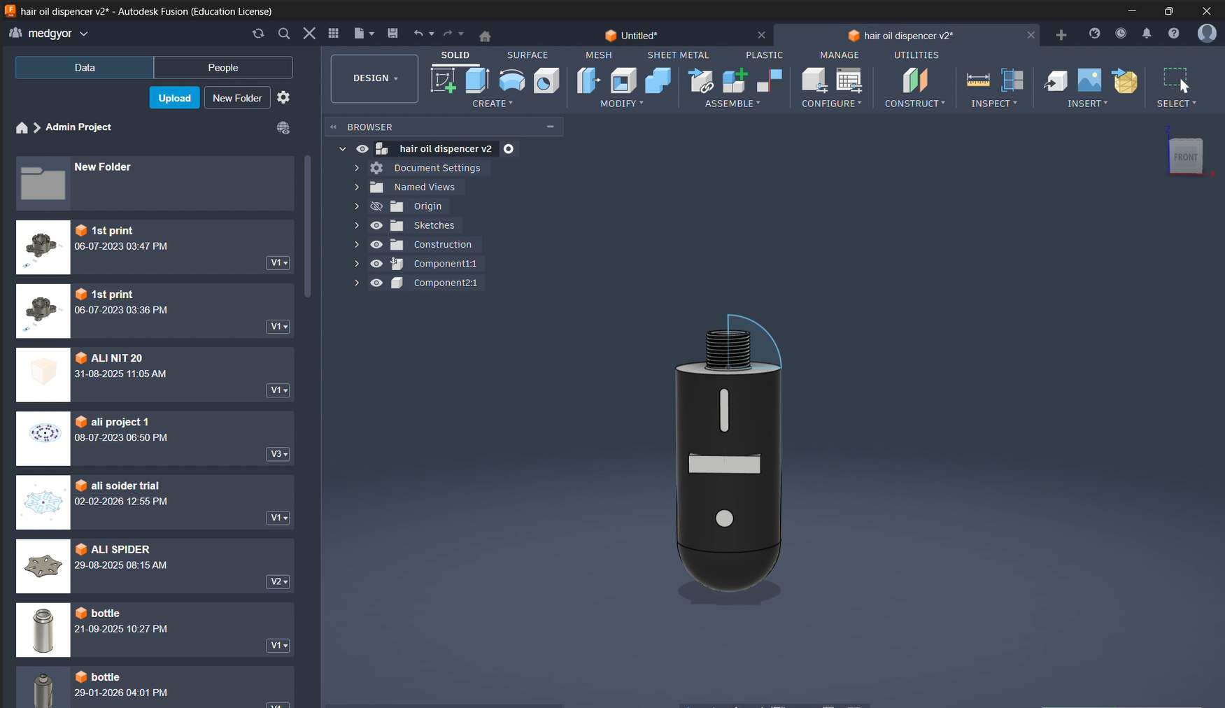
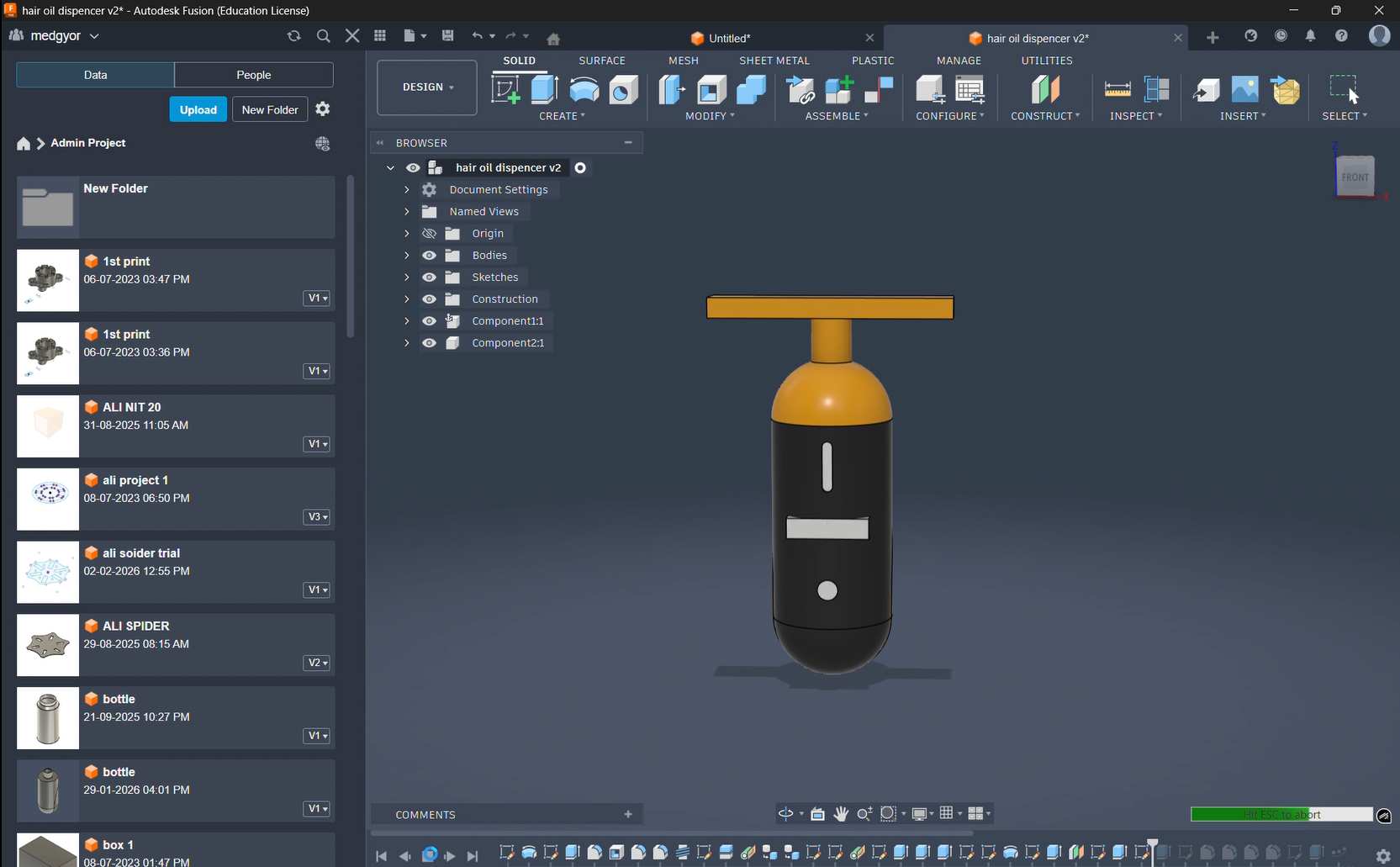
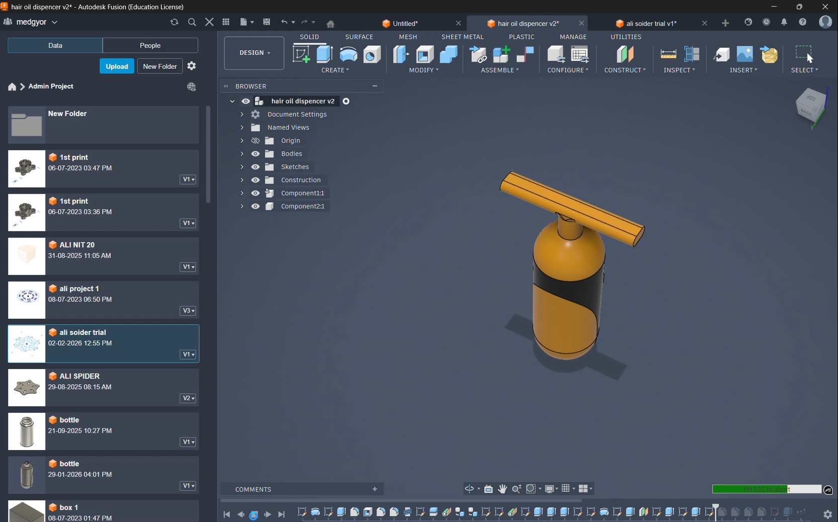
To create an extension from the bottle, I made a plane and then used the Extrude tool. This helps the user while applying oil, improves oil flow, and also makes the design look better.
This Bridge Across Bottle cap helps to distribute oil evenly on the head and saves time by avoiding repeated application.
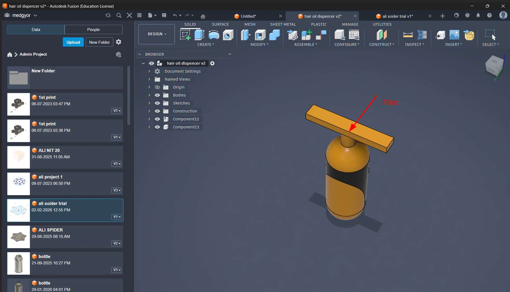
On the top, I added fillets to avoid oil getting trapped inside. This also makes it easier to clean and remove stains
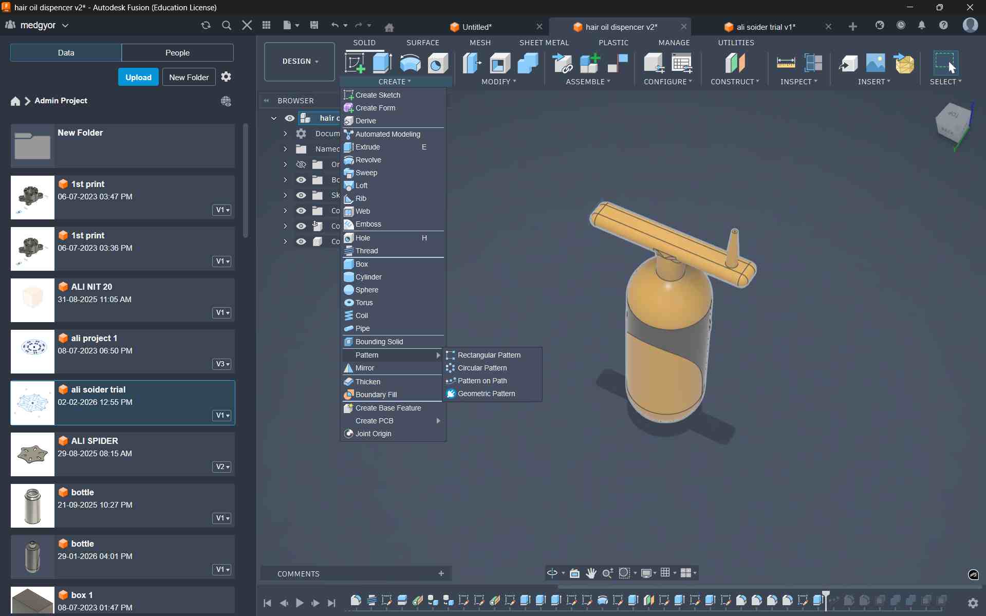
To dispense oil after the heating or cooling treatment, I designed a nozzle to apply the oil directly to the scalp. This helps the oil reach the roots properly, making the treatment more effective and supporting better hair growth.
Using Circular Pattern i created Multiple Nozile
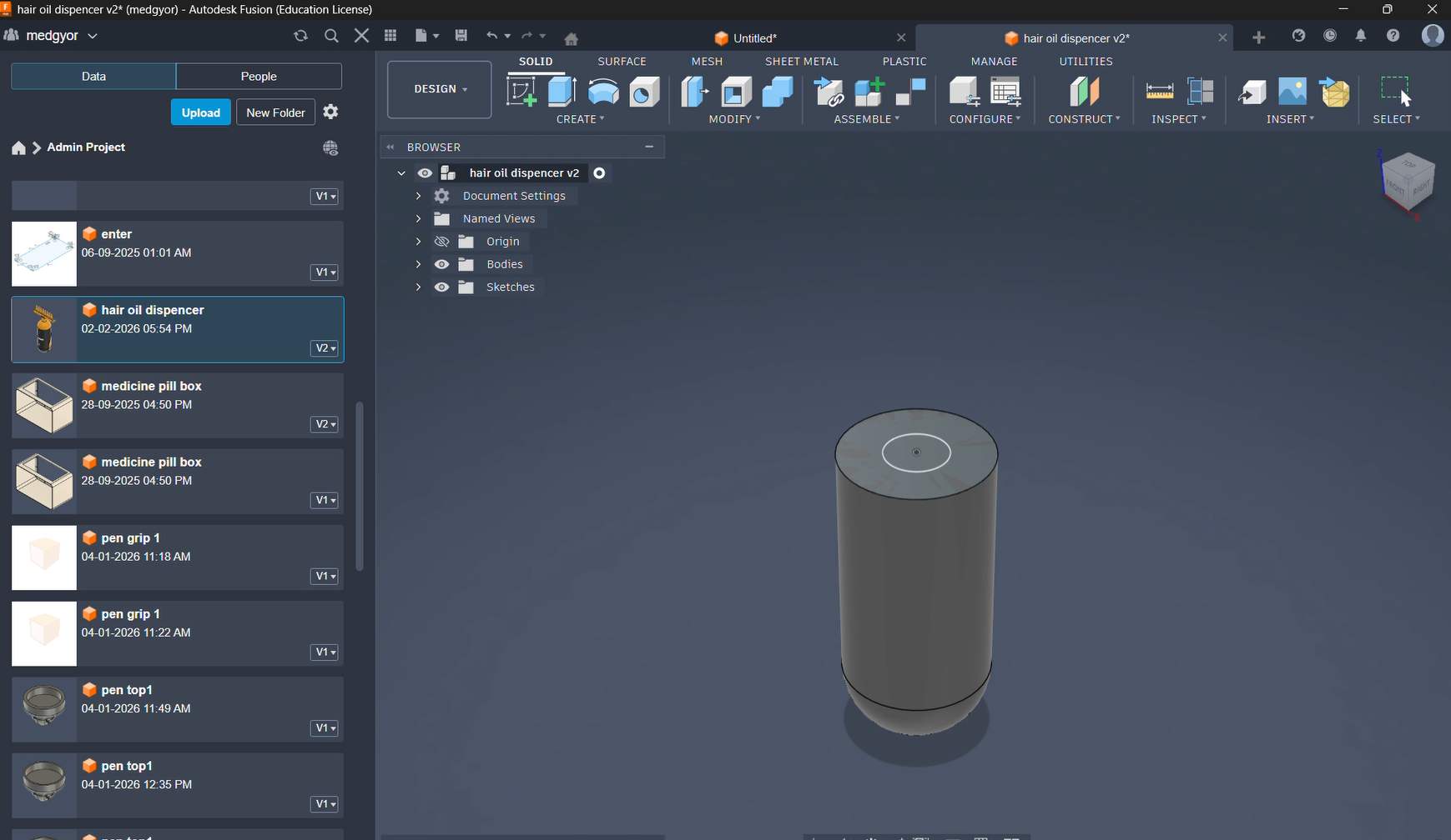
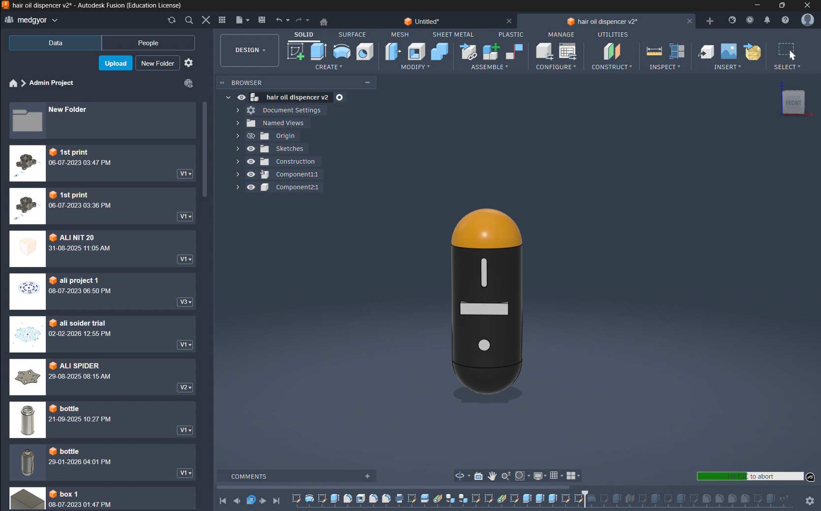
This Is The Final Output
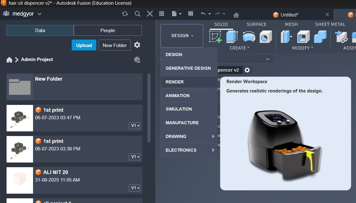
Applying Material and Rendering
By switching the design to the rendering workspace.
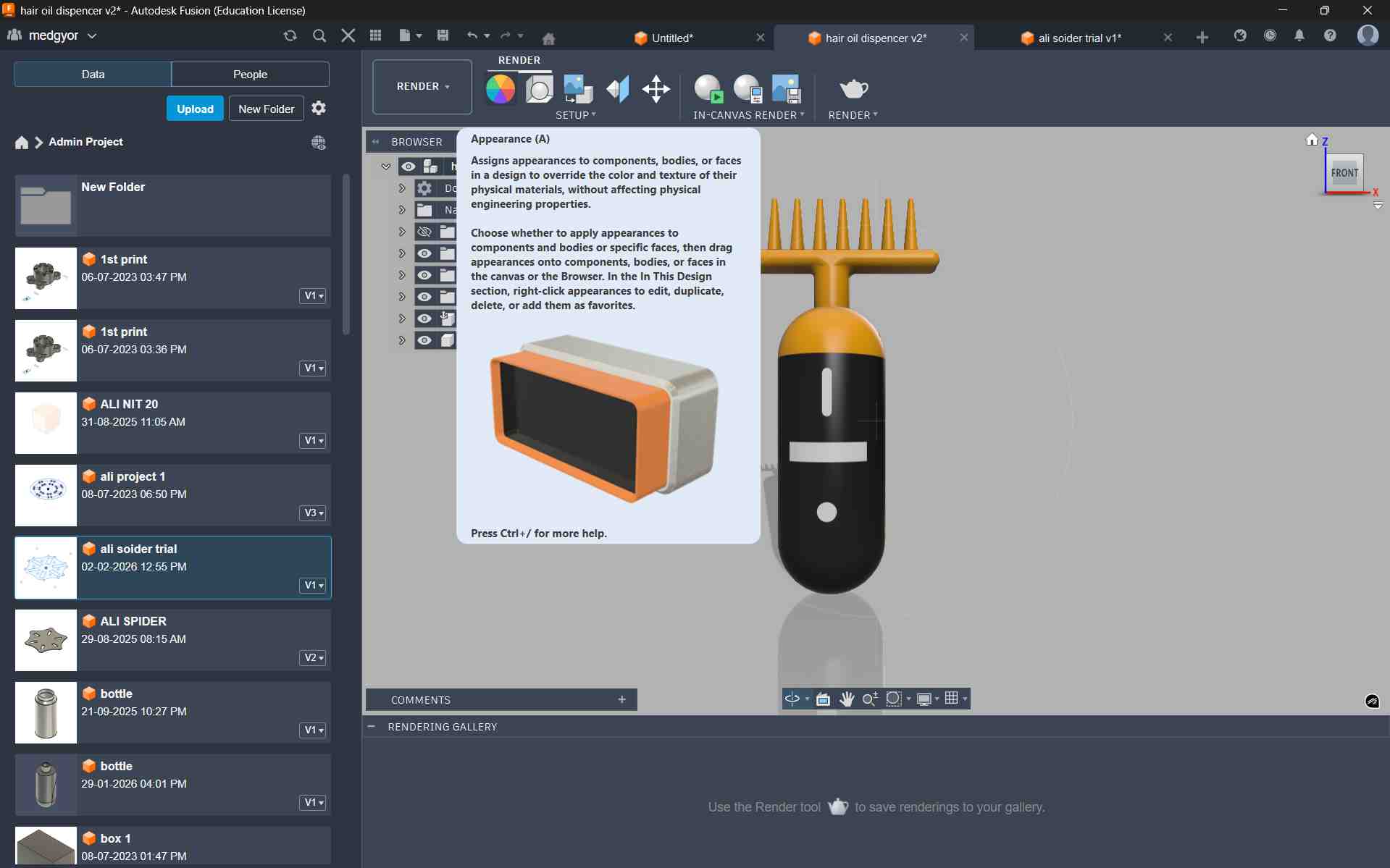
Then, from the toolbar, I selected the Appearance option. Using the Appearance tool, I added suitable colors to my model.
for scence setting i changed here settings
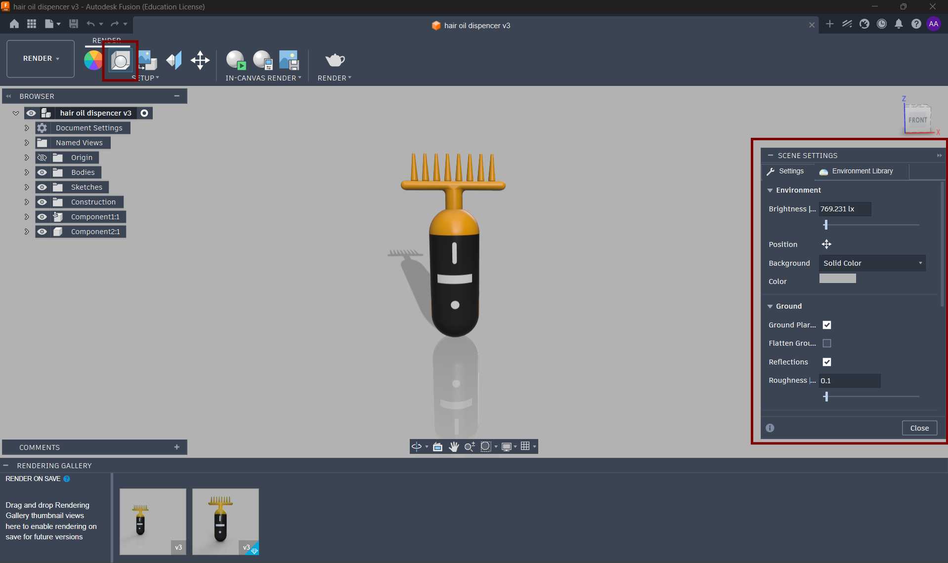
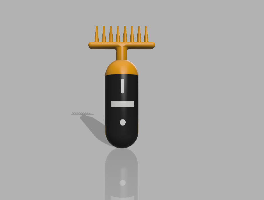
This is my final product after rendering. I am very happy to see the final result. This is my first time making a product like this. I learned many new things during the process, and it was a great experience for me.
This is a small timelapse video showing how I sketched and created my final product.
This is the rendered version of my product created using Fusion.You can rotate the model and view it from multiple angles.
Image and video Resize and Compression
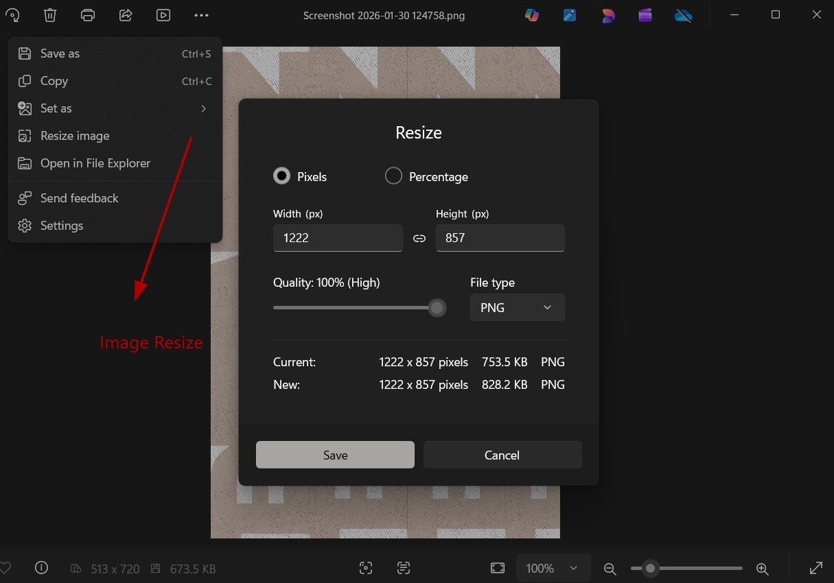
Image Resize
For image resizing and compression, I used the built-in Windows image resize option during the documentation process. This helped reduce image resolution and file size while maintaining sufficient visual quality for web documentation. Optimizing images in this way improves page loading speed and ensures efficient storage without affecting the clarity of the project details.
Video Resize
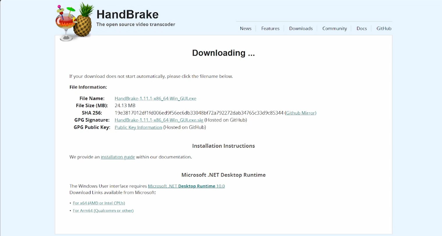
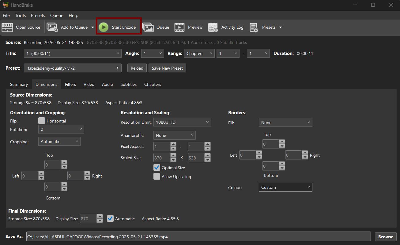
for video editing iam here using handbrake software to compress the video and reduce the file size. HandBrake is a free and open-source video transcoder that allows you to convert and compress video files while maintaining good quality. It provides various presets and customization options to optimize videos for web use, making it an ideal choice for resizing and compressing videos for documentation purposes.
Next we need to Set resolution into 1080p go to edit presets then edit preset then chnange resolution to 720p to 1080p
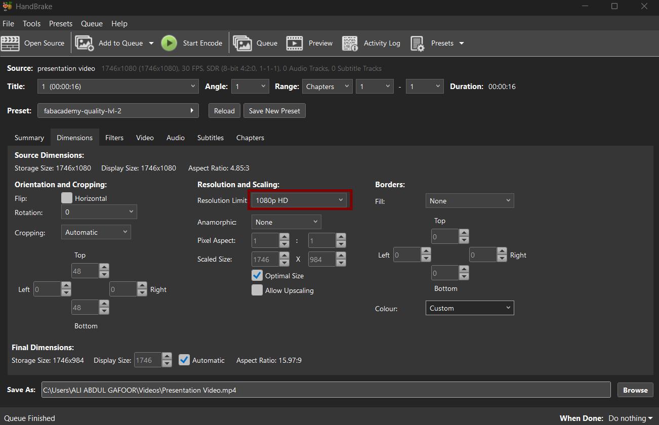
we only need to drag and droup the video into handbrake and click on start encode to start the compression process. After the process is complete, we will get a compressed video file that is optimized for web use and has a smaller file size, making it easier to upload and share on our documentation page.
References
Software & Tools
- Fusion 360 - 3D CAD/CAM software by Autodesk
- Blender - Free and open-source 3D creation suite
- Inkscape - Free and open-source vector graphics editor
- Tinkercad - Free online 3D modeling program
- OpenSCAD - Programmable CAD modeler
- Photopea - Free online photo editor
Resources & Documentation
- W3Schools - Web development tutorials
- Fab Academy - Digital fabrication course
Download Files
- Download ZIP File - Week 02 design files