Embedded Programming
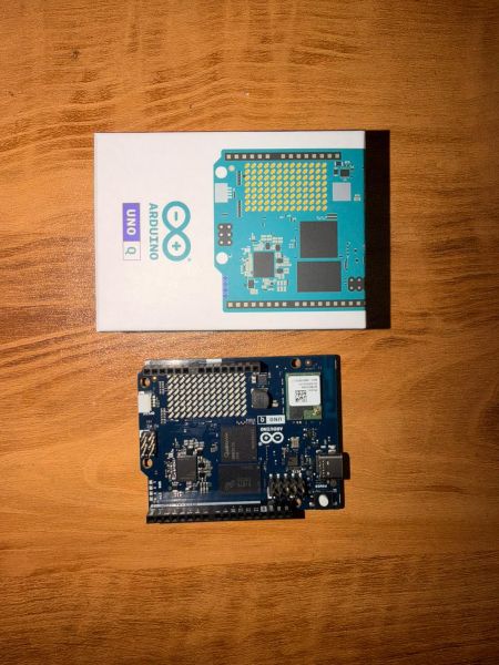
Arduino Q (UNO Q)
Arduino Q (also referred to as the Arduino UNO Q or UNO R4 WiFi) is a microcontroller development board that combines the simplicity of Arduino with the power of an industrial-grade microprocessor. It features a unique "Dual-Brain" architecture:
- A Microprocessor (MPU): Powered by the Qualcomm® QRB2210 (Quad-core ARM® Cortex®-A53). It runs a full Debian-based Linux OS, allowing for advanced tasks like Edge AI, Python scripting, and robust WiFi management.
- A Microcontroller (MCU): The STM32U585 (ARM® Cortex®-M33). This handles real-time hardware control, precise timing for pins, and the built-in LED matrix.
Unlike traditional Arduino boards, the UNO Q integrates a Linux-capable processor with AI acceleration, making its development workflow closer to embedded Linux systems than microcontroller-only platforms.
🛠 Setting Up Arduino Q (UNO Q)
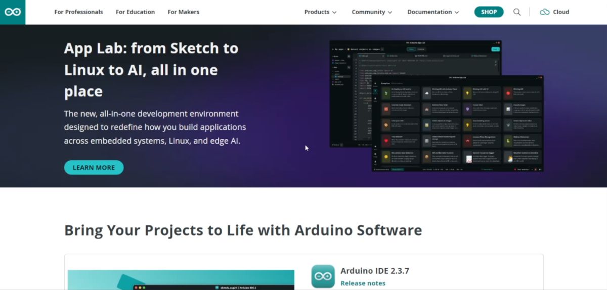
For full functionality—especially for WiFi and cloud control—I use Arduino Cloud / App Lab.
📥 Installation Steps
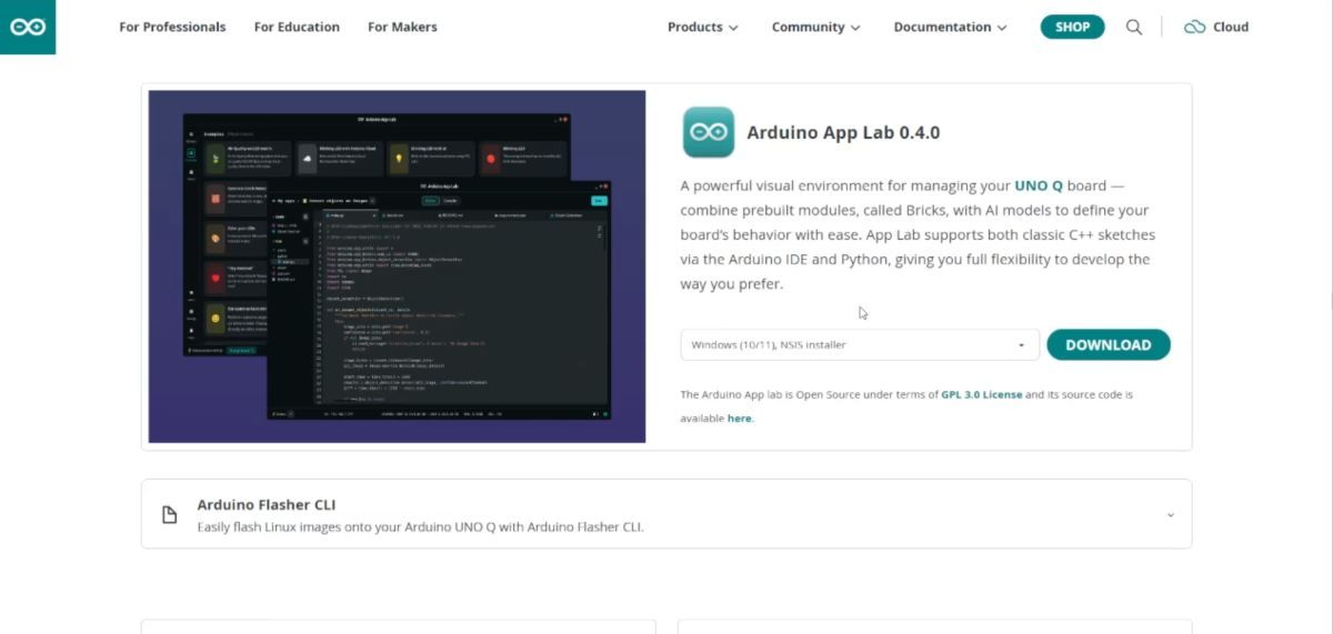
- Download: Go to the Arduino Software page and download Arduino App Lab / Arduino Cloud Agent.
- Open Application: Launch the application on your computer.
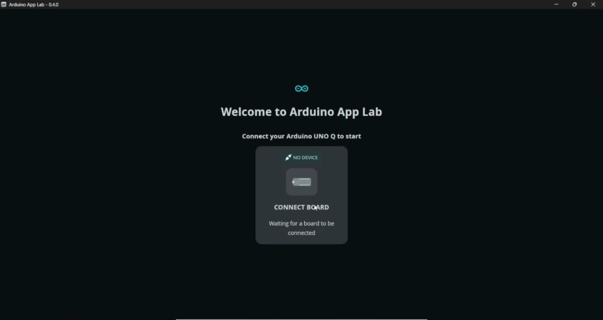
Connect: Plug in the Arduino Q (UNO R4 WiFi) using a USB-C cable.
Auto-Detection: The board should be auto-detected by the software.
Configuration:
- Set Device Name.
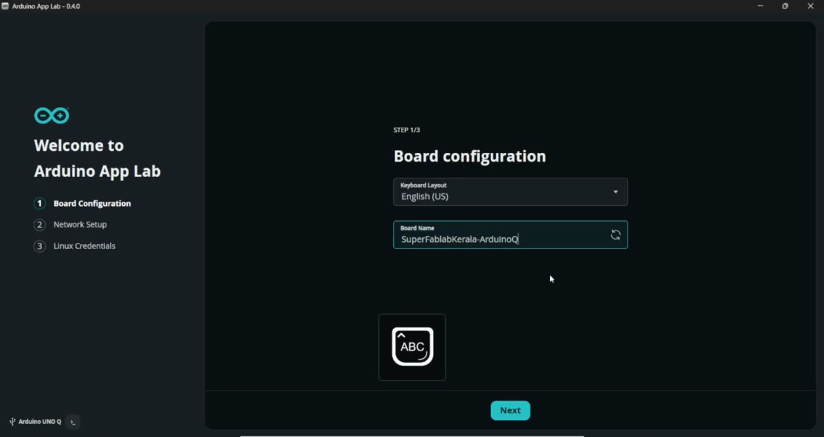
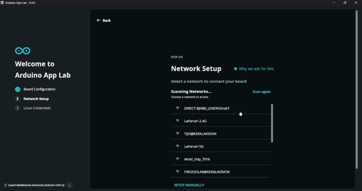
- Enter WiFi SSID and Password.
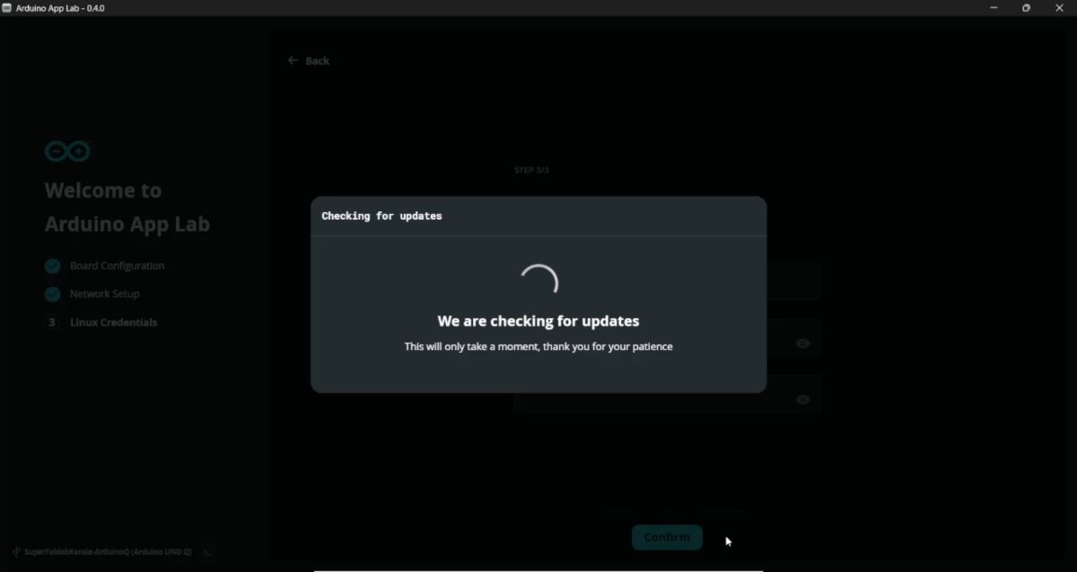
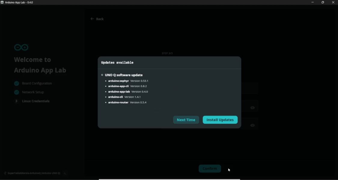
Firmware Update: Check for firmware updates and update if prompted.
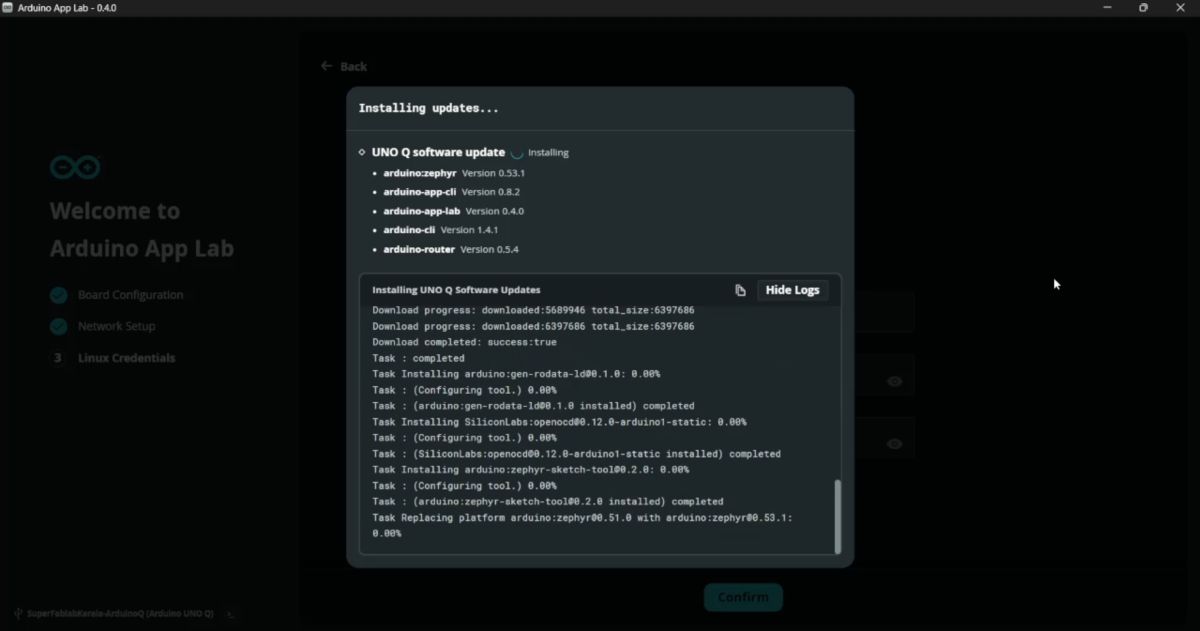
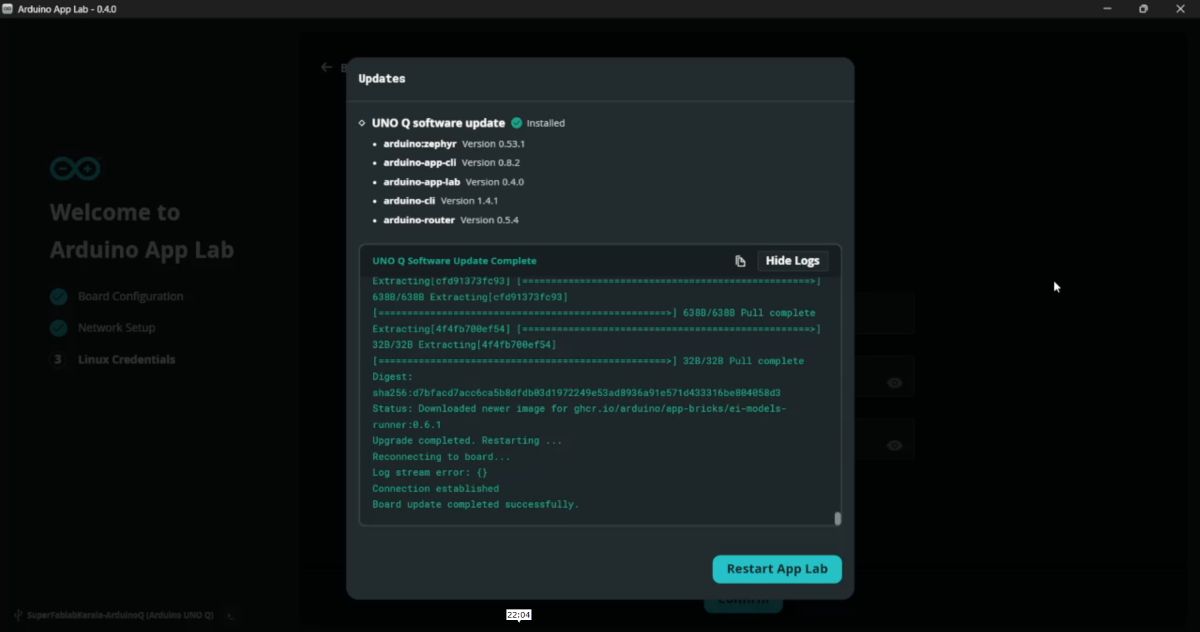
Linux Setup: Setup the Linux credentials.
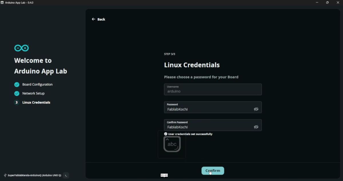
After setup, the board is ready for App Lab based programming.
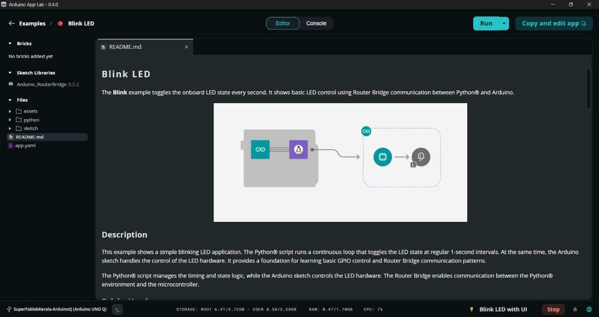
💡 Example 1 — Blink LED with UI
I tested the cloud functionality by running a basic blink sketch.
Select a built-in Blink example.
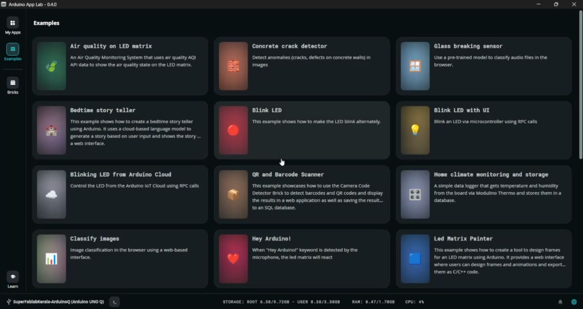
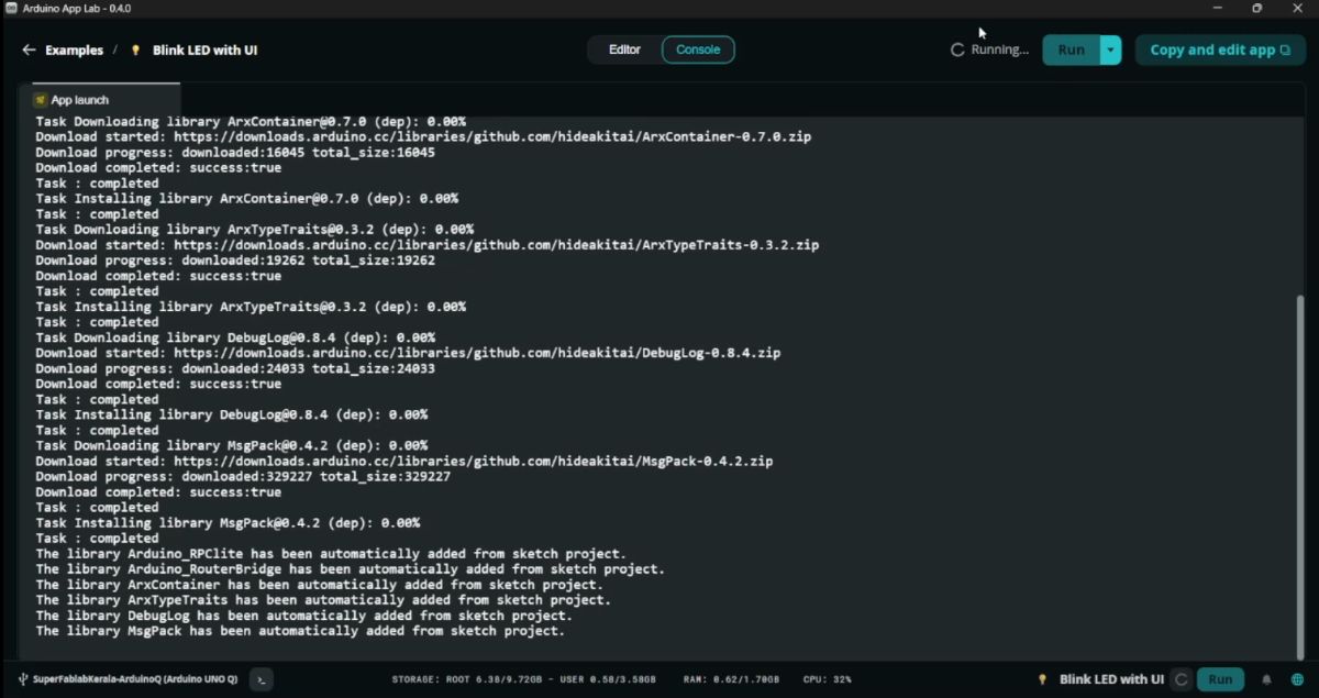
Click Run.
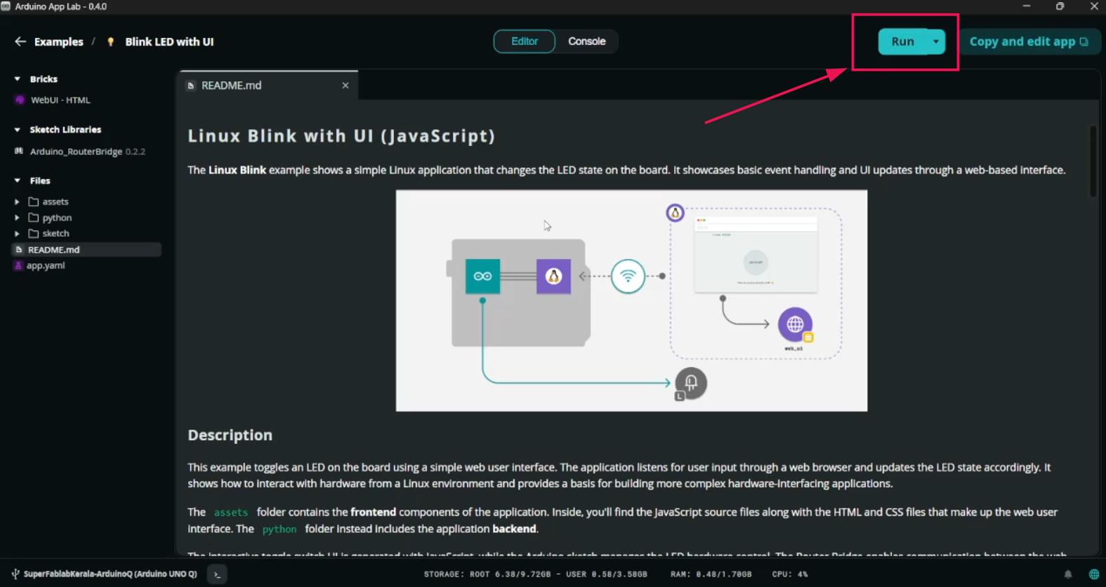
Code compiles automatically.
A webpage opens where the LED can be controlled from the browser.
💻 Arduino IDE Programming
Even though Cloud is available, the board can also be programmed using the Arduino IDE.
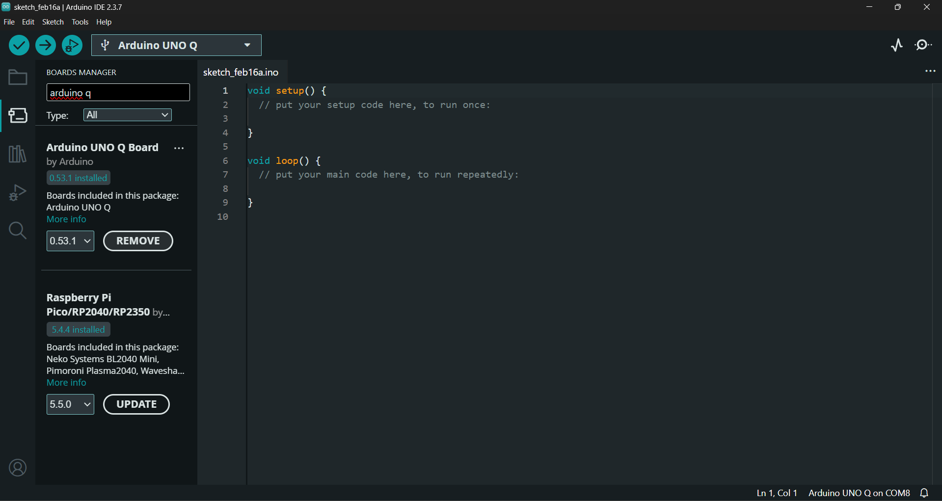
Step 1 — Install Board Package
Open Board Manager.
Install Arduino UNO Q Boards.
Step 2 — Install Required Libraries
Install the following libraries to use the display:
#include "ArduinoGraphics.h"#include "Arduino_LED_Matrix.h"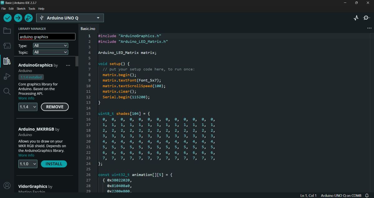
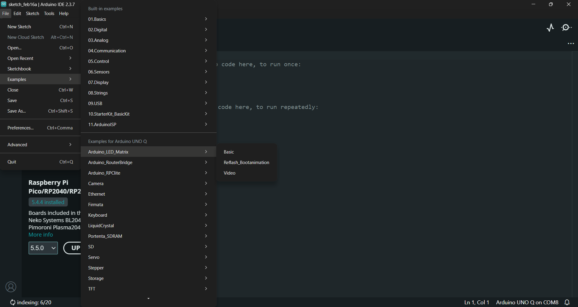
🟢 Example 2 — LED Matrix Animation + Text
Open the example code and select the Matrix Basic Code.
Code
#include "ArduinoGraphics.h"
#include "Arduino_LED_Matrix.h"

Arduino_LED_Matrix matrix;

void setup() {
  matrix.begin();
  matrix.textFont(Font_5x7);
  matrix.textScrollSpeed(100);
  matrix.clear();
  Serial.begin(115200);
}

uint8_t shades[104] = {
  0,0,0,0,0,0,0,0,0,0,0,0,0,
  1,1,1,1,1,1,1,1,1,1,1,1,1,
  2,2,2,2,2,2,2,2,2,2,2,2,2,
  3,3,3,3,3,3,3,3,3,3,3,3,3,
  4,4,4,4,4,4,4,4,4,4,4,4,4,
  5,5,5,5,5,5,5,5,5,5,5,5,5,
  6,6,6,6,6,6,6,6,6,6,6,6,6,
  7,7,7,7,7,7,7,7,7,7,7,7,7,
};

const uint32_t animation[][5] = {
  {0x38022020,0x810408a0,0x2200e800,0x20000000,66},
  {0x1c011010,0x40820450,0x11007400,0x10000000,66},
  {0x0e008808,0x20410228,0x08803a00,0x08000000,66},
  {0x07004404,0x10208114,0x04401d00,0x04000000,66},
  {0x03802202,0x0810408a,0x02200e80,0x02000000,66},
  {0x01c01101,0x04082045,0x01100740,0x01000000,66},
  {0x00e00880,0x82041022,0x808803a0,0x00000000,66},
  {0x00700440,0x40020011,0x004401c0,0x00000000,66},
  {0x00380200,0x20010008,0x802000e0,0x00000000,66},
  {0x00180100,0x10008004,0x00100060,0x00000000,66},
  {0x00080080,0x08004002,0x00080020,0x00000000,66},
  {0x00000040,0x04002001,0x00040000,0x00000000,66},
  {0x00000000,0x02001000,0x80000000,0x00000000,66},
  {0x00000000,0x00000000,0x00000000,0x00000000,66}
};

void loop() {

  matrix.beginText(0, 0, 127, 0, 0);
  matrix.print("      arduino.cc/uno-q      ");
  matrix.endText(SCROLL_LEFT);

  delay(1000);

  matrix.setGrayscaleBits(3);
  matrix.draw(shades);

  delay(1000);

  matrix.clear();

  matrix.loadSequence(animation);
  for (int i = 0; i < 10; i++) {
    matrix.playSequence();
  }
}
Action: I hit Compile and Upload.
Output: This example demonstrates:
Scrolling text
Custom animation
🧪 Custom LED Matrix Project
The next thing I tried out was printing on the LED matrix my own Custom Message. Below is the code for that.
Code
#include "ArduinoGraphics.h"
#include "Arduino_LED_Matrix.h"
Arduino_LED_Matrix matrix;

void setup() {
matrix.begin();
matrix.textFont(Font_5x7);
matrix.textScrollSpeed(60);
matrix.clear();
}

void loop() {
matrix.beginText(0, 0, 127, 0, 0);
matrix.print("   SUPERFABLAB KOCHI   FabAcademy 26   ");
matrix.endText(SCROLL_LEFT);

delay(500);
}
Output: The matrix displayed our custom group message.
🔄 Returning to App Lab: Basic Blink (No UI)
Then I got back to the App Lab and tested another basic blink—the one without any UI.
Action:
- Open Arduino App Lab.
- Select the Basic Blink example (the version without the Cloud/Web Switch).
- Click Run.
Output: The board reset and the LED started blinking immediately.
ESP32-C6
Step 1: Toolchain Installation on macOS
The process began with setting up a professional development environment. Unlike MicroPython, which is pre-installed, Assembly requires a native compiler on the host machine.
Caption: tool chain
- System Dependencies: Installed via Homebrew.
brew install libgcrypt glib pixman sdl2 libslirp dfu-util cmake python
- EIM GUI: Used the Espressif Installation Manager to handle the background setup of the RISC-V toolchain.
Caption: interface page
- VS Code Extension: Installed the ESP-IDF extension for a graphical interface to build and flash.
Caption: extension download
Step 2: Project Creation & Target Setting
I used a template to ensure the bootloader and partition tables were correctly configured.
- Generating the Project: Started with the get-started/blink example.
Caption: new project page
- Targeting RISC-V: Manually set the target to esp32c6 in the VS Code status bar.
- Observation: If this isn't set to C6, the compiler would try to use Xtensa logic (standard ESP32), which is architecturally incompatible with this chip.
Step 3: The "Assembly Pivot" & Initial Error
This phase involved transitioning from C to Assembly to interact directly with the silicon.
- The Change: Renamed the source file to main.S and updated CMakeLists.txt.
Caption: cmakelist page
The First Obstacle: Encountered an error stating the .elf file was missing. This occurred because the build system was holding onto old C-language artifacts.
The Troubleshooting: In collaboration with Gemini, I forced a "Clean" state via the terminal:
idf.py fullclean(Wiped the old build cache). idf.py set-target esp32c6 (Re-initialized the RISC-V environment).
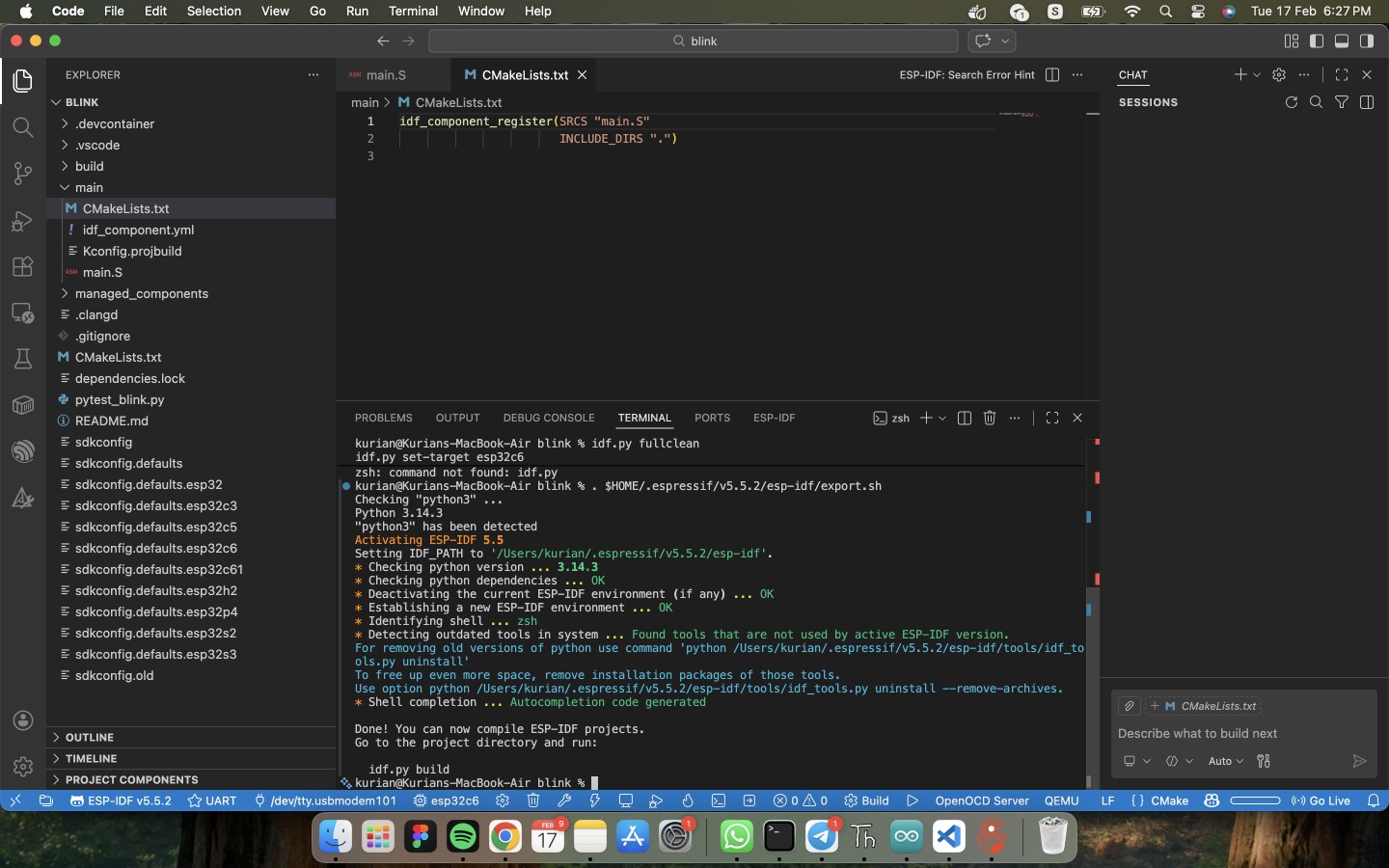
Caption: file clearing process
Step 4: The Assembly Implementation (main.S)
The following code was written in RV32I Assembly to control the GPIO registers directly.
\` assembly
PURE RISC-V ASSEMBLY FOR ESP32-C6
GPIO Base: 0x60091000
Offsets: Enable (+0x20), Set (+0x08), Clear (+0x0C)
.section .text .global app_main
app_main: # 1. Enable GPIO 14 as Output li t0, 0x60091000 # Load GPIO Base Address li t1, (1 << 14) # Bitmask for Pin 14
addi t3, t0, 0x20      # t3 = GPIO_ENABLE_REG
sw t1, 0(t3)           # Physically set pin to Output
loop: # 2. Set GPIO 14 HIGH (Turn LED ON) addi t3, t0, 0x08 # t3 = GPIO_OUT_W1TS_REG sw t1, 0(t3)
# 3. Delay (Busy-Wait Loop)
li t2, 5000000
1: addi t2, t2, -1 bnez t2, 1b
# 4. Set GPIO 14 LOW (Turn LED OFF)
addi t3, t0, 0x0C      # t3 = GPIO_OUT_W1TC_REG
sw t1, 0(t3)

# 5. Delay
li t2, 5000000
2: addi t2, t2, -1 bnez t2, 2b
j loop
\`
Caption: main.S page
Step 5: Successful Build and Flash
With a clean environment, the native compilation was successful.
Compiling: Executed idf.py build . This step took several minutes as it compiled the underlying system libraries for the RISC-V core.
Flashing: Deployed the code via the specific Mac USB port:
idf.py -p /dev/tty.usbmodem101 flash monitor
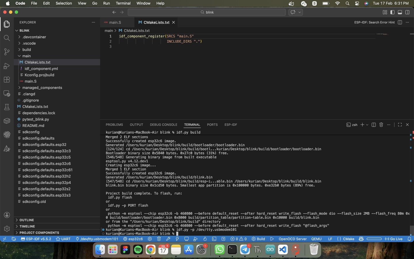
Caption: flashing process
- Result: The hardware responded immediately—the LED on the GLYPH C6 began to blink.
Step 6: Researching the "Magic Numbers"
To understand why the code worked, I moved from the general datasheet to the internal hardware specifications.
- Documentation Search: Realized the General Datasheet lacks register-level details. Switched to the Technical Reference Manual (TRM).
- Finding the Base Address: In Chapter 2 (Peripheral Address Mapping), I confirmed the GPIO Matrix is located at 0x60091000.
- Understanding Hex Offsets:
- 0x20: Enable Register (Sets the pin direction to Output).
- 0x08: Set Register (Pull pin High/3.3V).
- 0x0C: Clear Register (Pull pin Low/0V).
Code Logic & Observations
Analyzing the handwritten Assembly provided deep insights into processor behavior:
- Bitmasking: Learned that GPIOs are controlled via a 32-bit word. Defining "Pin 14" requires a math operation: (1 << 14), which flips the 14th "switch" in the control register.
- Addressing Limits: Discovered that RISC-V sw (store word) instructions cannot jump to a 32-bit address in a single step. I had to use addi to calculate the specific register address into a temporary register first.
- Busy-Wait Delay: In Assembly, a "Delay" is not a command but a mathematical waste of time. The CPU counts down from millions to zero, staying 100% active just to create a visible pause.
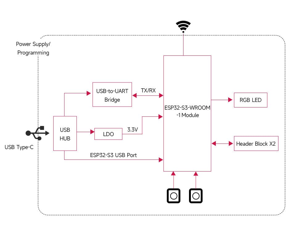
ESP32-S3-DEV_KIT-N8R8
ESP32-S3-DEV-KIT-NxR8 is a compact-size microcontroller development board with multiple digital interfaces.
In terms of hardware, it adopts ESP32-S3-WROOM-1-NxR8 module, which is equipped with a dual-core Xtensa 32-bit LX7 processor with 240MHz running frequency, built-in 512 KB SRAM (TCM) and 8MB PSRAM. Onboard CH343 and CH334 chips for USB and UART development via USB-C port. Compatible with the pinout of ESP32-S3-DevKitC-1 development board, more convenient to use and expand a variety of peripheral modules.
Software support:
- ESP-IDF
- Arduino
- MicroPython
Features
- Adopts ESP32-S3-WROOM-1-NxR8 module with Xtensa 32-bit LX7 dual-core processor, capable of running at 240 MHz
- Integrated 512KB SRAM, 384KB ROM, 8MB PSRAM, 8MB/16MB Flash memory
- Integrated 2.4GHz WiFi and Bluetooth LE dual-mode wireless communication, with superior RF performance
Functional Block Diagram
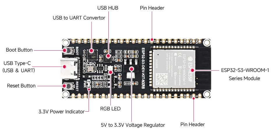
Interfaces
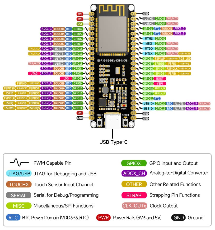
Pinout
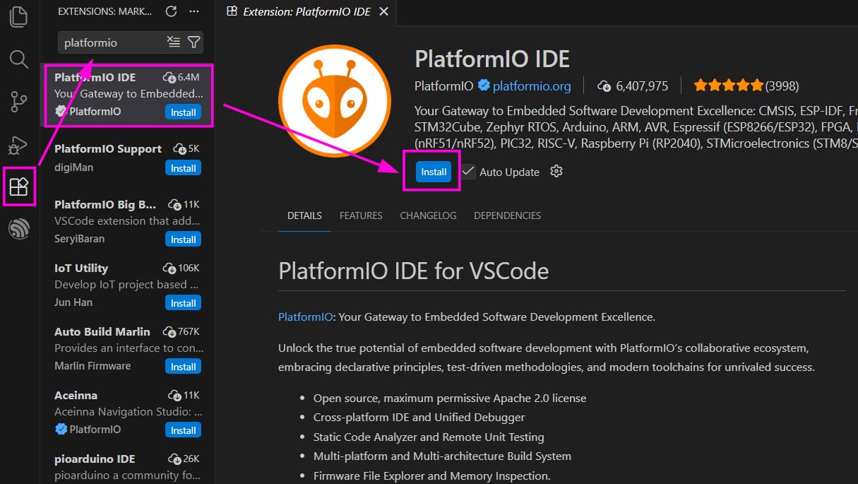
VSCode with PlatformIO
Development was done using Visual Studio Code with PlatformIO.
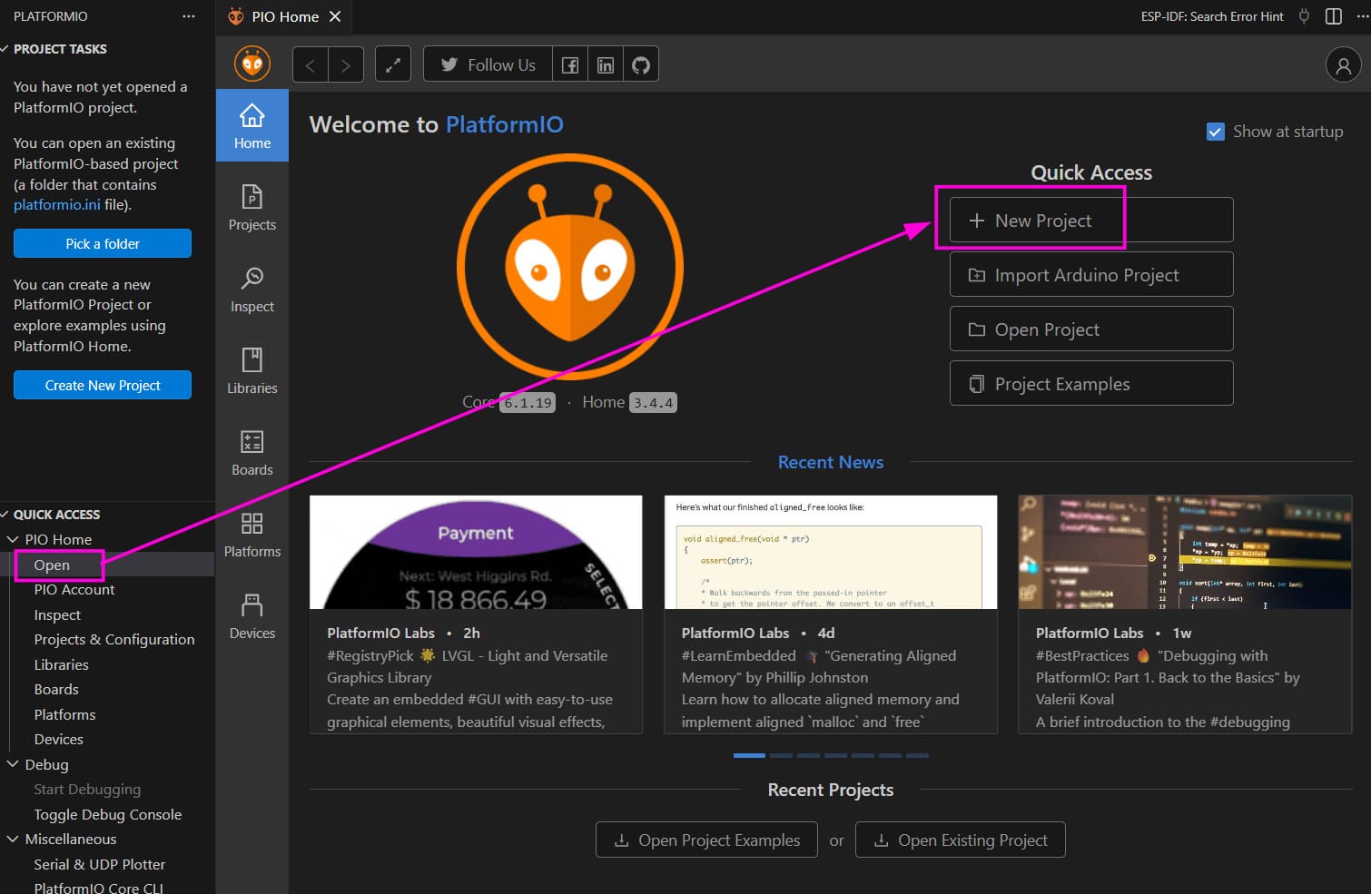
To install PlatformIO, install it from the VS Code extensions tab.
To start a new project, click on the new PlatformIO icon on the activity bar. Then click on Open in the quick access menu of PlatformIO. Using the New project option we can specify the name of project and type of board.
PlatformIO currently does not have a built-in board entry with that exact name in the official board list. However, the generic ESP32-S3 DevKitC series is a supported definition (Compatible with the pinout of ESP32-S3-DevKitC-1 development board).
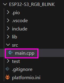
That board definition assumes no PSRAM, so PSRAM needs to be enabled manually in platformio.ini. The main application code is written in src/main.cpp.
How to RGB Blink the ESP32-S3
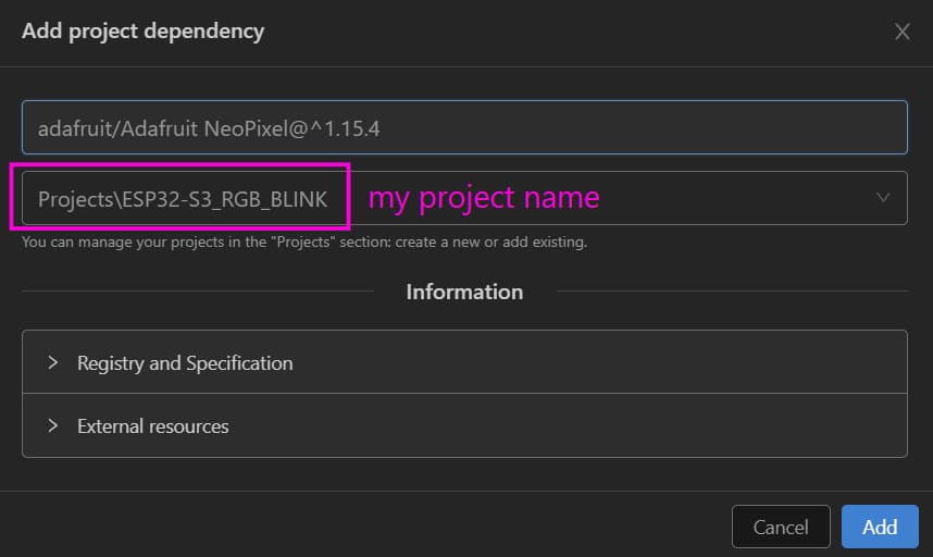
To include the Adafruit Neopixel library, search for it in the library tab on the PlatformIO quick access tab.
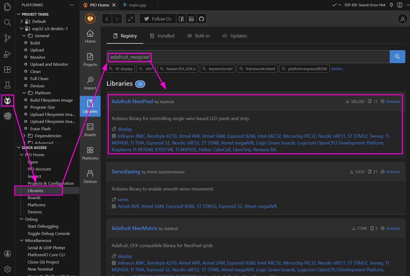
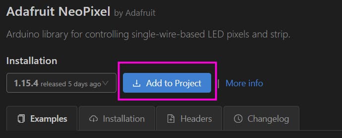
And then add it to your project
Code
#include <Adafruit_NeoPixel.h>

#define LED_PIN   48
#define LED_COUNT 1

Adafruit_NeoPixel led(LED_COUNT, LED_PIN, NEO_GRB + NEO_KHZ800);

void setup() {
  led.begin();
  led.setBrightness(150);   // 0–255
  led.show();               // Initialize all pixels to OFF
}

void loop() {
  // Red
  led.setPixelColor(0, led.Color(255, 0, 0));
  led.show();
  delay(2000);

  // Green
  led.setPixelColor(0, led.Color(0, 255, 0));
  led.show();
  delay(2000);

  // Blue
  led.setPixelColor(0, led.Color(0, 0, 255));
  led.show();
  delay(2000);
}
Key points:
- The RGB LED uses a single data pin with precise timing
NEO_GRB + NEO_KHZ800matches the WS2812 protocol- Brightness is global and affects power consumption
- GPIO 48 is the onboard RGB LED data pin on this board
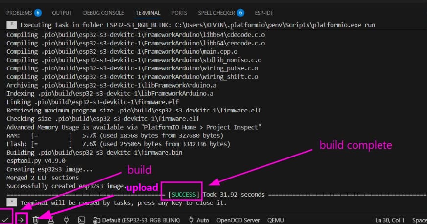
The RGB LED in the available dev kit was faulty, but to explore the toolchain we went through the entire process, just to check if the board was working simply blinked and external LED. using code-
#include <arduino.h>
#define LED_PIN 5

void setup() {
  pinMode(LED_PIN, OUTPUT);
  Serial.begin(115200);
  delay(1000);
  Serial.println("start");
}

void loop() {
  digitalWrite(LED_PIN, HIGH);  // LED ON
  Serial.println("led on");
  delay(1000);
  digitalWrite(LED_PIN, LOW);  // LED OFF
  Serial.println("led off");
  delay(1000);
}
ATtiny44/84
Elements of the Toolchain for Programming ATtiny44/84
The embedded firmware for the ATtiny44/84 microcontroller was developed using the C programming language within the Microchip Studio 7 integrated development environment (IDE). The required device/board support packages were installed to enable proper hardware definitions and register mappings for the ATtiny family. Code compilation was performed using the AVR-GCC compiler, which translates C source files into AVR machine code. The compiled firmware was generated as a HEX file and uploaded to the microcontroller using AVRDUDE in combination with an AVR ISP hardware programmer such as USBasp or Atmel ICE.
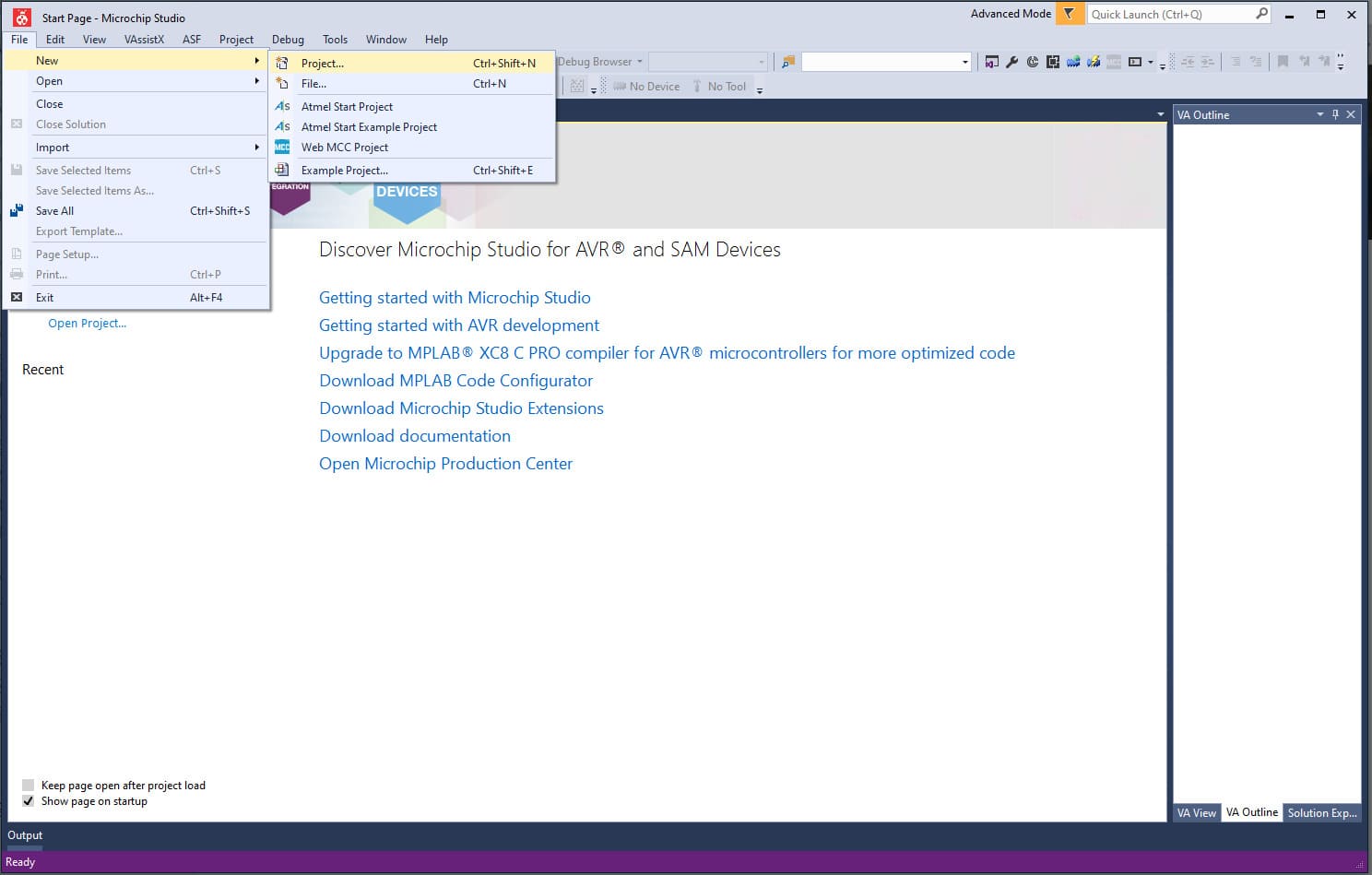
Microchip Studio 7 (formerly Atmel Studio) provides a complete environment for writing, compiling, and debugging C/C++ and assembly code for AVR microcontrollers. After installing the IDE, we created a new AVR project by navigating to File → New → Project, selecting the target ATtiny device, and proceeding with code development.
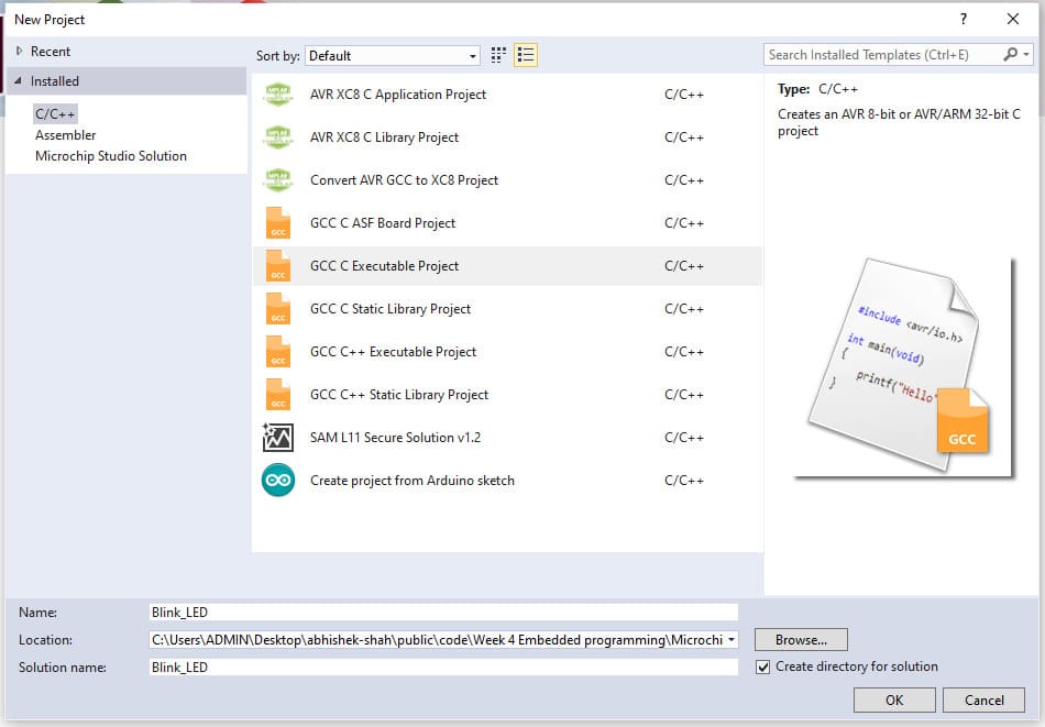
Next, we selected the GCC C Executable Project template, assigned the project name “Blink_LED”, and clicked OK to proceed. This created a new project workspace configured for C-based firmware development using the AVR-GCC compiler.
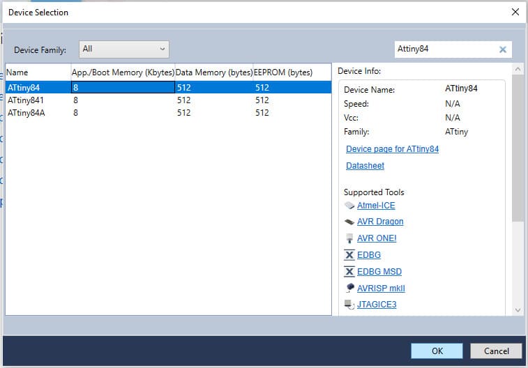
In the next window, we searched for ATtiny84 and selected it as the target microcontroller. This automatically loaded the relevant device files, register definitions, and hardware support resources required for programming the selected chip, ensuring proper configuration of the project environment.
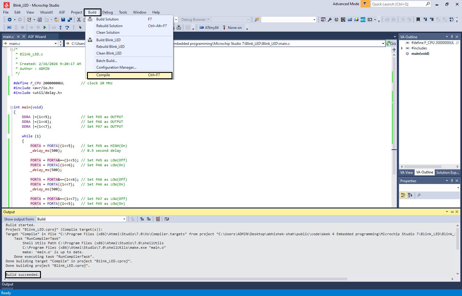
After selecting the device, the IDE automatically opened a main.c file (shown as main.cpp in the interface) containing a basic template to simplify program development. we began writing a simple LED blink program by including the required time delay library for timing control. During this process, we referred to my instructor Saheen Palayi’s documentation for guidance. Once the code was completed, we navigated to Build → Compile to check for any compilation errors before proceeding further.
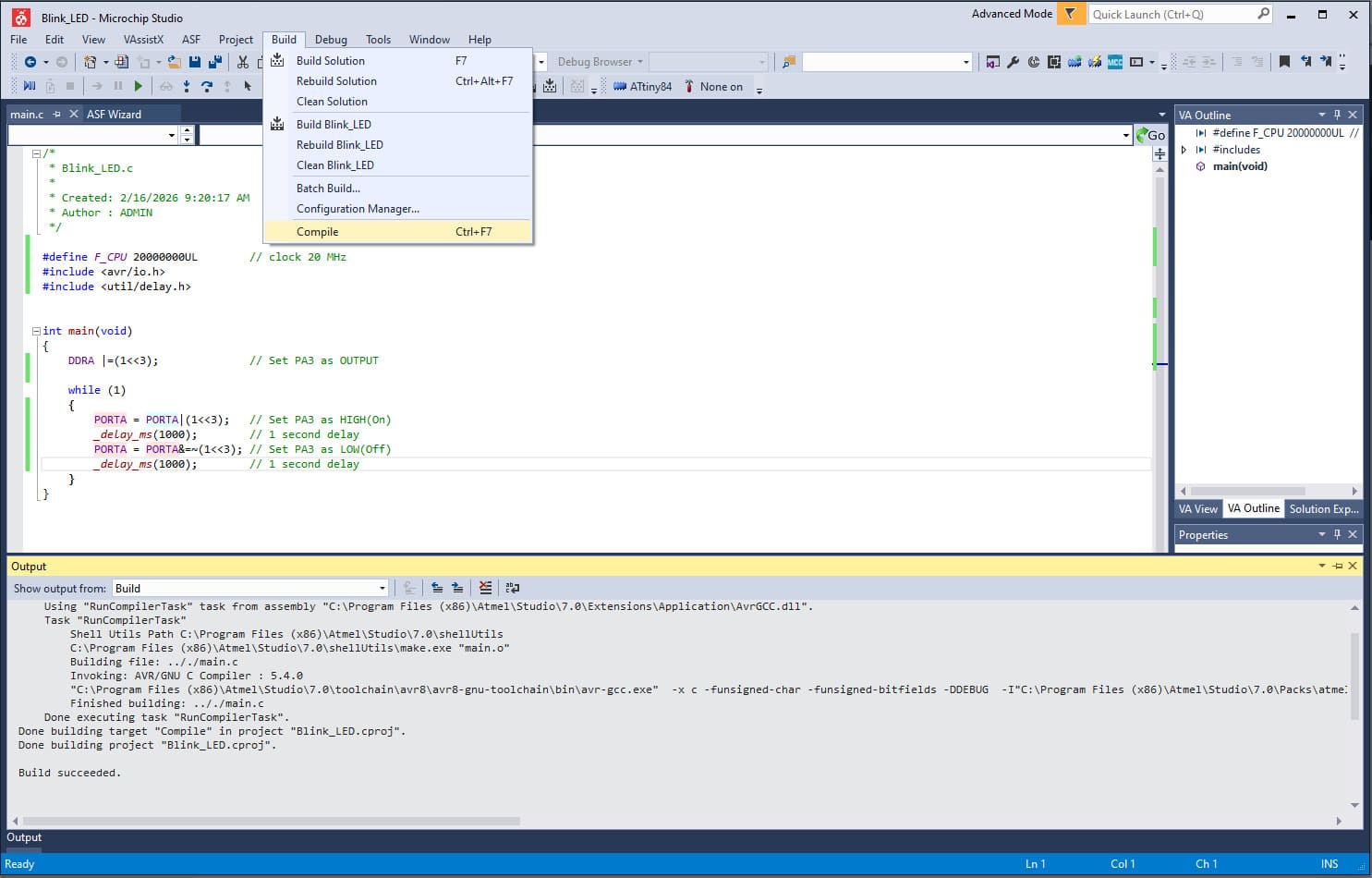
Compiling the program alone is not sufficient in Microchip Studio, as the firmware must be converted into a HEX file before it can be uploaded to the microcontroller. To generate this file, we navigated to Build → Build Solution, which created the compiled output file Blink_LED.hex in the project’s Debug folder.
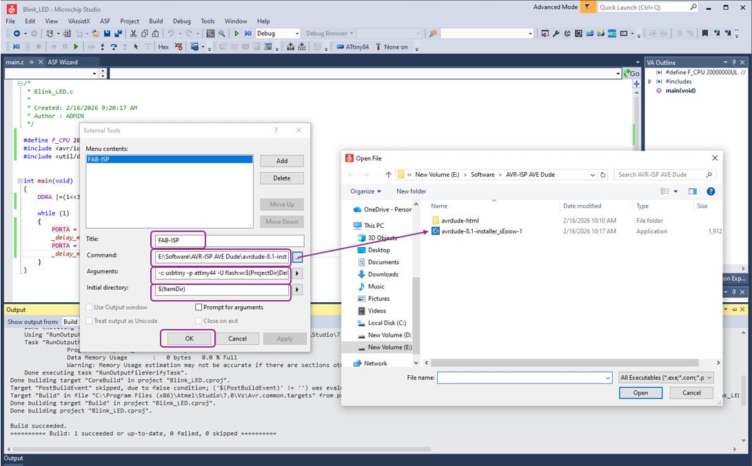
To program the ATtiny84 using my FAB TinyISP programmer, we needed to configure an external upload tool within Microchip Studio. Since Microchip Studio primarily supports official programmers such as Atmel-ICE, we manually added a custom external tool to interface with AVRDUDE. (Download Link : https://github.com/avrdudes/avrdude/releases?utm_source=chatgpt.com)
We added a new tool by navigating to Tools → External Tools, and entered the following argument configuration:
Argument : -c usbtiny -p attiny84 -U flash:w:$(ProjectDir)Debug\$(TargetName).hex:i
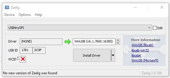
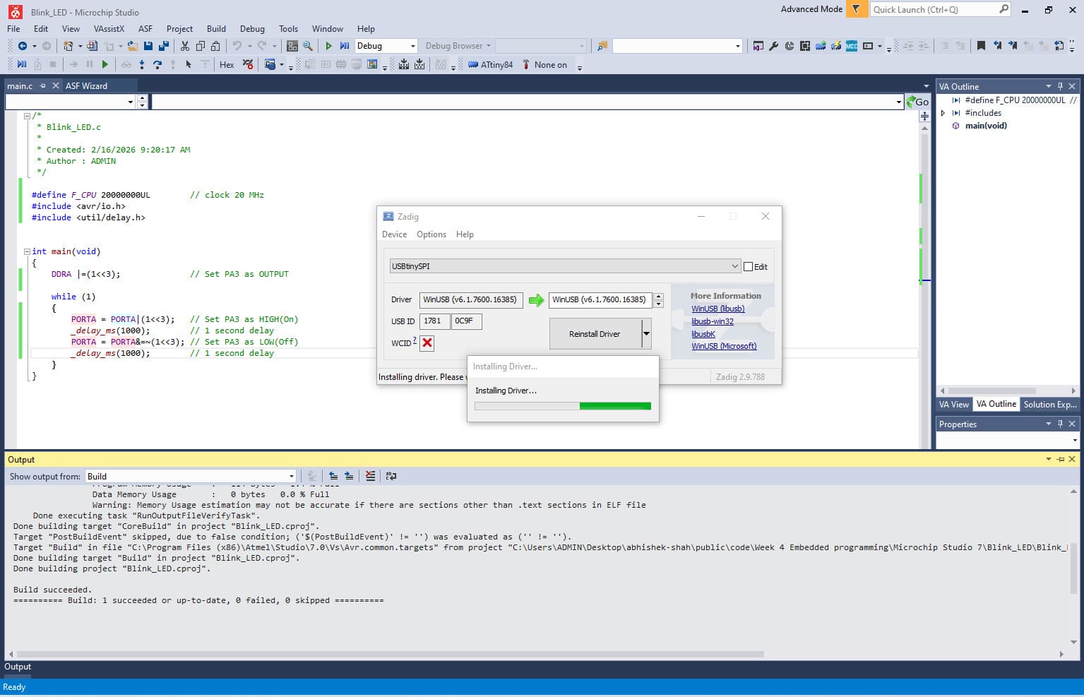
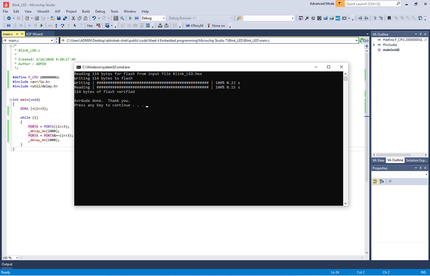
Next, we connected the target board to my computer using the FAB ISP programmer. Once the connection was established, we navigated to Tools → FAB-ISP in Microchip Studio to upload (flash) the generated HEX file onto the ATtiny microcontroller. This process transferred the compiled firmware to the board’s flash memory, enabling the program to run immediately after programming. Most common installing the USBtiny driver (Download link :https://zadig.akeo.ie/)
Click Options → List All Devices >> Select something like >> USBtinyISP
After Installing the driver we tried again and it worked! It flashed at lightning speed, it was super quick compared to Arduino and MicroPython, because it is using Embedded C.
/*
- Blink_LED.c
- Created: 2/16/2026 9:20:17 AM
- Author : ADMIN */
#define F_CPU 20000000UL // clock 20 MHz #include <avr/io.h> #include <util/delay.h>
int main(void) { DDRA |=(1<<3); // Set PA3 as OUTPUT
while (1)
{
	PORTA = PORTA|(1<<3);	// Set PA3 as HIGH(On)
	_delay_ms(1000);		// 1 second delay
	PORTA = PORTA&=~(1<<3);	// Set PA3 as LOW(Off)
	_delay_ms(1000);		// 1 second delay
}
}
Now we tried a new program to control a common Anode Neo Pixel connected on PA5 PA6 and PA7 Pins of ATtiny84.
/*
- Blink_LED.c
- Created: 2/16/2026 9:20:17 AM
- Author : ADMIN */
#define F_CPU 20000000UL // clock 20 MHz #include <avr/io.h> #include <util/delay.h>
int main(void) { DDRA |=(1<<5); // Set PA5 as OUTPUT DDRA |=(1<<6); // Set PA6 as OUTPUT DDRA |=(1<<7); // Set PA7 as OUTPUT
while (1)
{
	PORTA = PORTA|(1<<5);	// Set PA5 as HIGH(On)
	_delay_ms(500);			// 0.5 second delay

	PORTA = PORTA&=~(1<<5);	// Set PA5 as LOW(Off)
	PORTA = PORTA|(1<<6);	// Set PA6 as LOW(On)
	_delay_ms(500);

	PORTA = PORTA&=~(1<<6);	// Set PA6 as LOW(Off)
	PORTA = PORTA|(1<<7);	// Set PA6 as LOW(On)
	_delay_ms(500);

	PORTA = PORTA&=~(1<<7);	// Set PA7 as LOW(Off)
	PORTA = PORTA|(1<<5);	// Set PA5 as LOW(On)
	_delay_ms(500);

}
}
Once Code is ready we can click on Built>>Compile. Output will show Build succeeded. Now we can Upload the using Tool >> FAB ISP and Done! It will flash very quickly compared to Arduino and MicroPython.
Elements of the Toolchain for Programming ATtiny44/84
The embedded firmware for the ATtiny44/84 microcontroller was developed using the C programming language within the Microchip Studio 7 integrated development environment (IDE). The required device/board support packages were installed to enable proper hardware definitions and register mappings for the ATtiny family. Code compilation was performed using the AVR-GCC compiler, which translates C source files into AVR machine code. The compiled firmware was generated as a HEX file and uploaded to the microcontroller using AVRDUDE in combination with an AVR ISP hardware programmer such as USBasp or Atmel ICE.
Microchip Studio 7 (formerly Atmel Studio) provides a complete environment for writing, compiling, and debugging C/C++ and assembly code for AVR microcontrollers. After installing the IDE, we created a new AVR project by navigating to File → New → Project, selecting the target ATtiny device, and proceeding with code development.
Next, we selected the GCC C Executable Project template, assigned the project name “Blink_LED”, and clicked OK to proceed. This created a new project workspace configured for C-based firmware development using the AVR-GCC compiler.
In the next window, we searched for ATtiny84 and selected it as the target microcontroller. This automatically loaded the relevant device files, register definitions, and hardware support resources required for programming the selected chip, ensuring proper configuration of the project environment.
After selecting the device, the IDE automatically opened a main.c file (shown as main.cpp in the interface) containing a basic template to simplify program development. we began writing a simple LED blink program by including the required time delay library for timing control. During this process, we referred to my instructor Saheen Palayi’s documentation for guidance. Once the code was completed, we navigated to Build → Compile to check for any compilation errors before proceeding further.
Compiling the program alone is not sufficient in Microchip Studio, as the firmware must be converted into a HEX file before it can be uploaded to the microcontroller. To generate this file, we navigated to Build → Build Solution, which created the compiled output file Blink_LED.hex in the project’s Debug folder.
To program the ATtiny84 using my FAB TinyISP programmer, we needed to configure an external upload tool within Microchip Studio. Since Microchip Studio primarily supports official programmers such as Atmel-ICE, we manually added a custom external tool to interface with AVRDUDE. (Download Link : https://github.com/avrdudes/avrdude/releases?utm_source=chatgpt.com)
We added a new tool by navigating to Tools → External Tools, and entered the following argument configuration:
Argument : -c usbtiny -p attiny84 -U flash:w:$(ProjectDir)Debug\$(TargetName).hex:i
Next, we connected the target board to my computer using the FAB ISP programmer. Once the connection was established, we navigated to Tools → FAB-ISP in Microchip Studio to upload (flash) the generated HEX file onto the ATtiny microcontroller. This process transferred the compiled firmware to the board’s flash memory, enabling the program to run immediately after programming. Most common installing the USBtiny driver (Download link :https://zadig.akeo.ie/)
Click Options → List All Devices >> Select something like >> USBtinyISP
After Installing the driver we tried again and it worked! It flashed at lightning speed, it was super quick compared to Arduino and MicroPython, because it is using Embedded C.
/*
- Blink_LED.c
- Created: 2/16/2026 9:20:17 AM
- Author : ADMIN */
#define F_CPU 20000000UL // clock 20 MHz #include <avr/io.h> #include <util/delay.h>
int main(void) { DDRA |=(1<<3); // Set PA3 as OUTPUT
while (1)
{
	PORTA = PORTA|(1<<3);	// Set PA3 as HIGH(On)
	_delay_ms(1000);		// 1 second delay
	PORTA = PORTA&=~(1<<3);	// Set PA3 as LOW(Off)
	_delay_ms(1000);		// 1 second delay
}
}
Now we tried a new program to control a common Anode Neo Pixel connected on PA5 PA6 and PA7 Pins of ATtiny84.
/*
- Blink_LED.c
- Created: 2/16/2026 9:20:17 AM
- Author : ADMIN */
#define F_CPU 20000000UL // clock 20 MHz #include <avr/io.h> #include <util/delay.h>
int main(void) { DDRA |=(1<<5); // Set PA5 as OUTPUT DDRA |=(1<<6); // Set PA6 as OUTPUT DDRA |=(1<<7); // Set PA7 as OUTPUT
while (1)
{
	PORTA = PORTA|(1<<5);	// Set PA5 as HIGH(On)
	_delay_ms(500);			// 0.5 second delay

	PORTA = PORTA&=~(1<<5);	// Set PA5 as LOW(Off)
	PORTA = PORTA|(1<<6);	// Set PA6 as LOW(On)
	_delay_ms(500);

	PORTA = PORTA&=~(1<<6);	// Set PA6 as LOW(Off)
	PORTA = PORTA|(1<<7);	// Set PA6 as LOW(On)
	_delay_ms(500);

	PORTA = PORTA&=~(1<<7);	// Set PA7 as LOW(Off)
	PORTA = PORTA|(1<<5);	// Set PA5 as LOW(On)
	_delay_ms(500);

}
}
Once Code is ready we can click on Built>>Compile. Output will show Build succeeded. Now we can Upload the using Tool >> FAB ISP and Done! It will flash very quickly compared to Arduino and MicroPython.
Toolchain & LED Blink Comparison
This comparison focuses specifically on toolchain setup and LED blink implementation across four microcontroller platforms. The evaluation is based only on practical experience with development environment configuration and basic GPIO blinking.
| Board | Development Environment | Programming Level | Build Process | Flashing Method | Blink Implementation Style | Observed Complexity |
|---|---|---|---|---|---|---|
| Arduino Q (UNO R4 WiFi) | Arduino IDE / Arduino Cloud | High-level C++ | Automatic compile & upload | USB (One-click) | digitalWrite() | Very Easy |
| ESP32-C6 | VS Code + ESP-IDF | C / Assembly (RISC-V) | idf.py build (manual build system) | idf.py flash | Direct GPIO register control | High |
| ESP32-S3-DEV-KIT | VS Code + PlatformIO | C++ (Arduino Framework) | PlatformIO build system | USB via PlatformIO | digitalWrite() / NeoPixel library | Medium |
| ATtiny44/84 | Microchip Studio + AVR-GCC | Embedded C | Compile → Generate HEX | AVRDUDE + ISP Programmer | Direct PORT register manipulation | Medium (Low-level) |
Summary Observations
- Arduino Q provided the most beginner-friendly and abstracted workflow.
- ESP32-C6 required the most advanced configuration and exposed low-level hardware interaction.
- ESP32-S3 offered a structured ecosystem with moderate complexity.
- ATtiny44/84 required manual compilation and flashing, giving deeper insight into embedded C and register-level programming.
Conclusion
The comparison highlights how toolchain structure and abstraction level vary significantly between platforms. While all four boards successfully executed a basic LED blink program, the setup complexity, build process, and programming depth differed substantially. This demonstrates how architecture and ecosystem design directly influence the embedded development experience.