Computer-Aided Cutting
Group Assignment Objectives
The objective of the group assignment was to understand, operate, and characterize the laser cutting machines available in the lab. This included completing mandatory safety training, studying laser cutter operation, and experimentally determining key parameters such as focus, power, speed, frequency (rate), kerf, joint clearance, and suitable joint types for press-fit construction.
About Our Laser Cutter
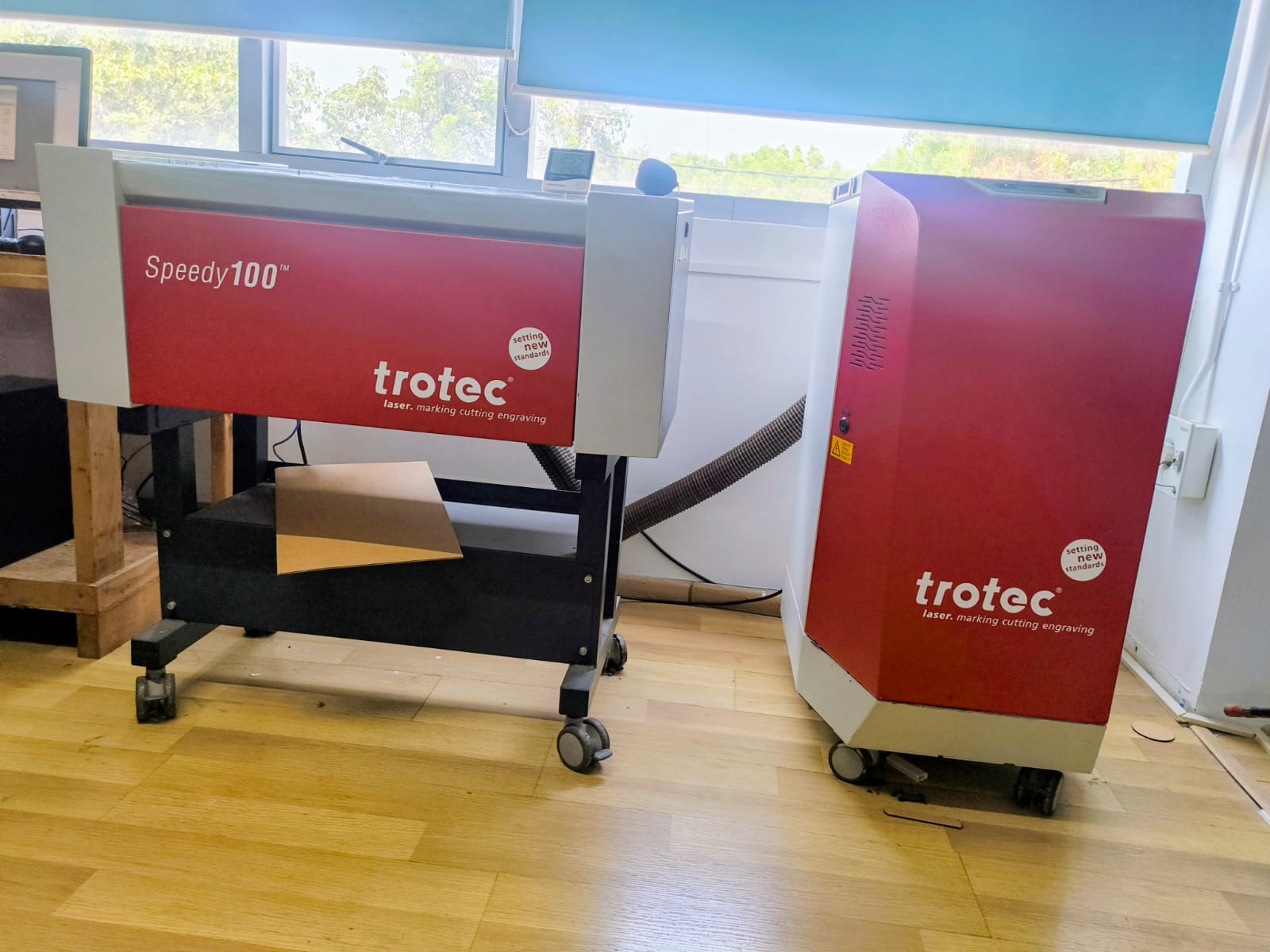
Our lab is equipped with a Trotec Speedy 100 CO₂ Laser Cutter along with a Trotec exhaust filtration system. This machine is designed for high-precision laser cutting, engraving, and marking of various materials.
The Speedy 100 is a professional-grade laser system commonly used in digital fabrication labs for prototyping, press-fit construction kits, parametric design experiments, and engraving applications.
Laser Cutter Safety Measures
Operating a laser cutter requires strict adherence to safety protocols to prevent fire hazards, material damage, and exposure to harmful fumes. The following safety measures must always be followed in the lab.
1. Pre-Operation Safety Checks
Confirm that the exhaust vent is operating properly.
Check that the laser bed is clean and free of debris.
Measure material thickness accurately before setting focus.
Confirm that the material is laser-safe (Never cut PVC, ABS, or unknown plastics).
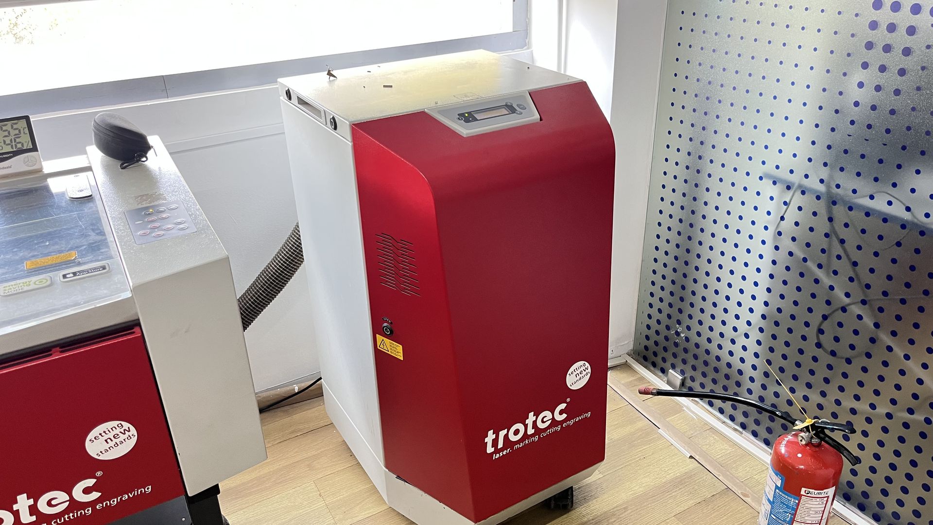
Laser Exhaust
2. Personal Safety
Never leave the laser cutter unattended while it is operating.
Keep hands away from moving parts (gantry, belts, and Z-axis).
Avoid placing reflective objects inside the machine.
Keep long hair tied back and avoid loose clothing near the machine.
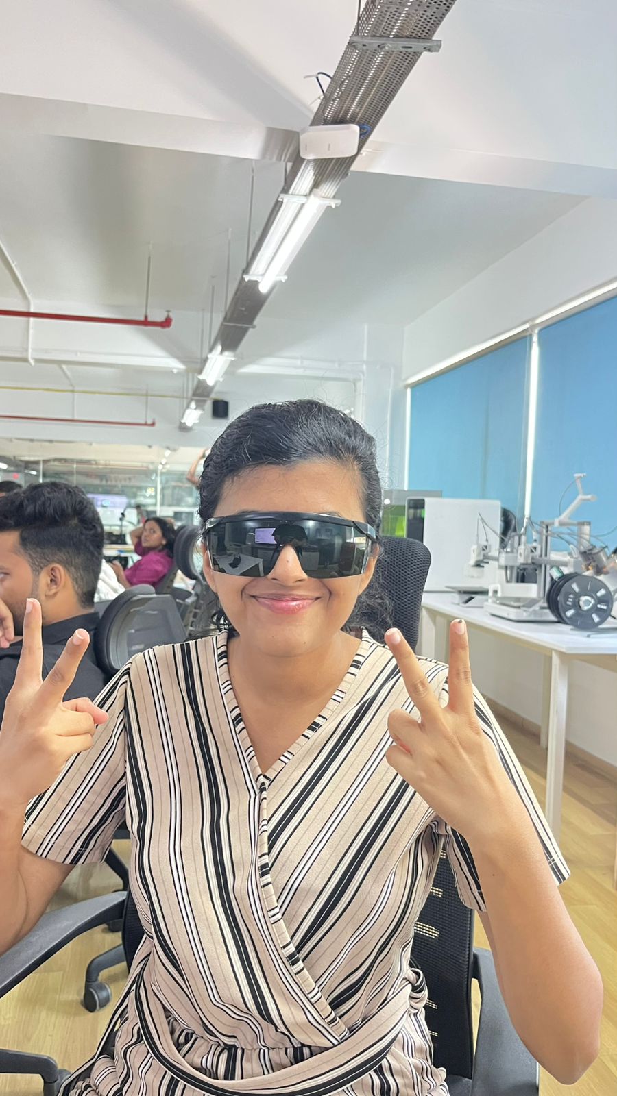
Do not look directly at the laser beam. Always wear Safety Glasses
3. Fire Prevention Measures
Laser cutting generates heat and can ignite materials, especially cardboard and wood.
Always monitor the cutting process.
Avoid using excessive power or very low speed unnecessarily.
Ensure proper focus to prevent overheating.
Keep the cutting bed clean to avoid flare-ups from debris.
Fire Safety Equipment
A CO₂ fire extinguisher must be kept nearby.
A fire-smothering board or blanket (same size as the laser bed) must be accessible.
Know the location of emergency exits.
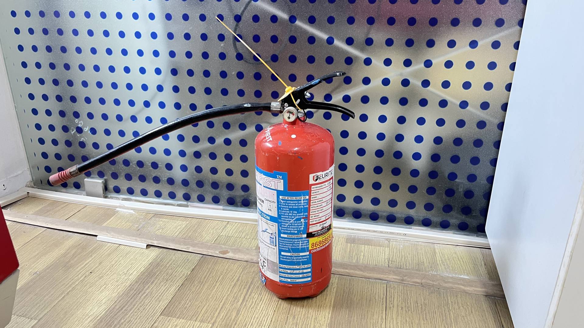
Fire Extinguisher
4. What To Do If a Fire Starts
Do NOT open the lid immediately.
Opening the lid introduces oxygen and may worsen the fire.
Pause the machine immediately to stop the laser source.
Allow the flame to extinguish while keeping the lid closed.
If the flame is small, use a non-flammable board or sheet to smother the flame while keeping the lid closed.
If the fire does not stop quickly:
Use a CO₂ fire extinguisher.
Do NOT use water (risk of electrical damage).
If the fire spreads or cannot be controlled:
Evacuate the lab.
Call emergency assistance.
5. During Operation
Keep the lid closed at all times while cutting.
Observe the cutting quality and watch for excessive flames.
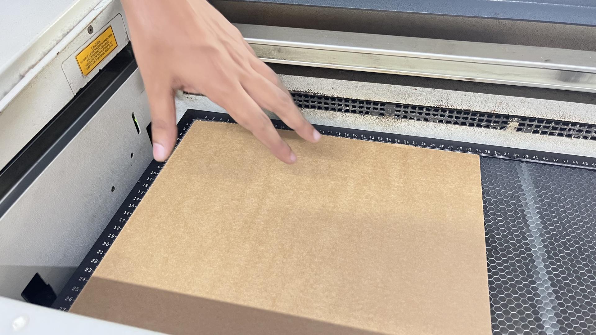
Ensure the material lies flat on the bed.
Do not attempt to adjust material while the machine is running.
6. Post-Operation Procedure
Wait for all fumes to clear before opening the lid.
Remove finished parts carefully.
Clean leftover debris from the cutting bed.
Switch off the laser cutter properly.
Keep the exhaust running for 15–20 minutes after cutting.
7. Prohibited Materials
The following materials must NEVER be cut:
PVC (releases chlorine gas)
ABS (produces toxic fumes)
Unknown plastics
Materials containing chlorine
These materials release hazardous gases that damage the machine and pose serious health risks.
Conclusion
Safe laser cutter operation requires:
Proper ventilation
Constant supervision
Fire readiness
Correct material selection
Accurate focusing
Following these safety measures ensures safe operation, protects equipment, and maintains a secure lab environment.
It was noted that visible smoke inside the laser chamber indicates improper airflow or incorrect parameters and requires immediate machine stoppage.
Machine Model
- Brand: Trotec
- Model: Speedy 100
- Laser Type: CO₂ Laser
- Applications: Cutting, raster engraving, vector engraving, marking
Main Features of the Trotec Speedy 100
1️⃣ High Precision CO₂ Laser Tube
The machine uses a CO₂ laser source which produces an infrared laser beam. This beam is ideal for cutting and engraving non-metal materials such as:
- Cardboard
- MDF
- Plywood
- Acrylic
- Paper
- Leather
- Certain plastics
The laser beam is extremely focused, allowing clean and accurate cuts with minimal material waste.
Infrared wavelength (~10.6 µm)
2️⃣ Adjustable Power and Speed Control
The machine allows control over:
- Power (%) – Determines laser intensity
- Speed (%) – Determines how fast the laser head moves
- Frequency (Hz) – Controls pulse rate during vector cutting
These parameters are adjusted depending on:
- Material type
- Material thickness
- Desired effect (engrave vs cut)
Higher power + lower speed → deeper cut
Lower power + higher speed → light engraving
Power in JobControl is usually set in percentage (%).
Example:
100% power = full laser output
50% power = half of max output
🔹 Laser Power
(Depends on installed tube – most FabLabs use:)
- 30W / 60W options
- Our lab machine: 60W
🔹 Working Area (Bed Size)
610 mm × 305 mm
(24" × 12")
This defines the maximum sheet size that can be cut at once.
3️⃣ Raster and Vector Processing
The machine supports two main operation modes:
Raster Engraving
- Laser moves back and forth (like a printer)
- Used for images, filled areas, text engraving
- Depth depends on power settings
Vector Cutting
- Laser follows defined paths/lines
- Used for cutting shapes and outlines
- Produces precise edges suitable for press-fit joints
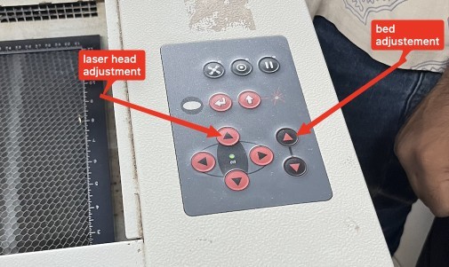
4️⃣ Motorized Z-Axis (Focus Control)
The Speedy 100 includes an adjustable bed height (Z-axis).
This allows proper focusing of the laser beam depending on material thickness.
Correct focus ensures:
- Clean cuts
- Minimum kerf variation
- Reduced burning
- Better edge quality
5️⃣ Enclosed Safety Design
The machine has:
- A fully enclosed cutting chamber
- A protective transparent lid
- Safety interlocks that stop the laser when the lid is opened
- Emergency stop button
This ensures safe operation and prevents exposure to laser radiation.
What is Focus?
Focus is the distance between the laser lens and the surface of the material where the laser beam becomes the smallest and most concentrated.
At the correct focus:
The beam is very thin
Energy is highly concentrated
Cuts are clean and sharp
If focus is wrong:
Cut becomes wide
Edges burn more

Exhaust and Filtration System
Our machine is connected to a Trotec exhaust filtration unit, visible as the red external box connected through a large ventilation hose.
Why the Exhaust System is Important
During laser cutting:
- Materials burn or vaporize
- Smoke and fine particles are produced
- Toxic fumes may be generated (depending on material)
The exhaust system removes these fumes and protects:
- The user
- The machine optics
- The lab environment
How the Exhaust System Works
- When the laser cutter starts operating, the exhaust system turns on.
- Smoke generated inside the cutting chamber is pulled out through the ventilation hose.
- The smoke passes through internal filtration stages:
- Particle filters
- Activated carbon filters (to absorb odors and chemicals)
- Clean air is either:
- Released safely back into the room, or
- Directed outside (depending on installation setup)
This system ensures:
- No visible smoke during cutting
- Clean air inside the lab
- Reduced fire risk
Air Assist System
The Speedy 100 includes an air assist system that blows compressed air directly at the cutting point.
This helps to:
- Prevent flame formation
- Reduce burning marks
- Improve edge quality
- Remove debris from the cutting area
How Laser Cutting Works
Explanation of the basic principles behind laser cutting, including the types of lasers used (CO2, fiber, neodymium) and the cutting process.
A laser cutter operates by focusing high-energy light into a narrow beam capable of cutting, engraving, or marking materials. LASER stands for Light Amplification by Stimulated Emission of Radiation.
At the atomic level, atoms are excited from a ground state to a higher energy state. When they return to the lower state, light is emitted and amplified within an optical cavity. Mirrors and lenses guide and focus this light to a very small point known as the beam waist.
 credit : laser image
Types of Laser Cutting Systems
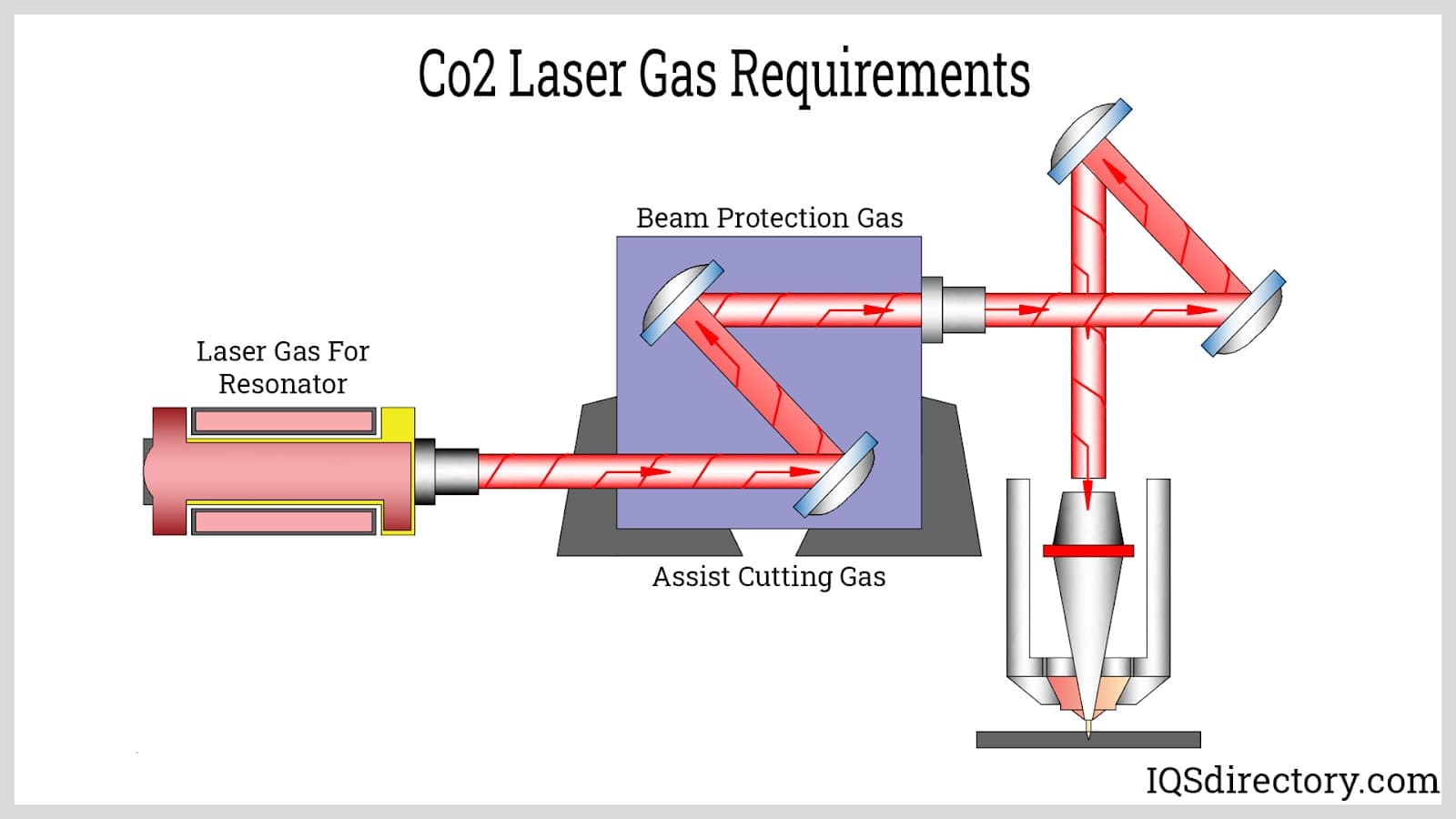
CO₂ Laser Cutter
The CO₂ laser cutter operates at a wavelength of approximately 10 microns in the far infrared spectrum. The laser source remains stationary inside a tube, and mirrors guide the beam to the cutting head.
CO₂ lasers are highly effective for cutting and engraving non-metallic materials such as cardboard, wood, acrylic, and fabric. Regular cleaning of mirrors and lenses is required for consistent performance.
Diode Laser Cutter
Diode lasers operate in the visible or near-infrared range. The laser diode is mounted directly on the moving head, eliminating the need for mirror routing. These machines are simpler to maintain and are typically used for light engraving and low-power cutting.
Fiber Laser
Fiber lasers operate at shorter wavelengths (around 1 micron) and are more energy efficient. They are capable of cutting metals and, at lower power, removing copper for PCB fabrication. Fiber lasers are often paired with galvo scanners for fast, depth-controlled engraving.
Neodymium (Nd:YAG) Lasers
High-power lasers used for cutting thick materials and for applications requiring deep penetration.
Materials Available for Laser Cutting
Cardboard
Cardboard was identified as the most suitable material for this assignment. High-quality cardboard bends smoothly without forming sharp creases, indicating good structural properties for press-fit joints. Heavy-duty shipping boxes and cardboard pads were used.
Wood
Wood can be laser cut effectively, but thickness variation can affect joint accuracy. Dimensionally stable sheet materials such as plywood and MDF provided better results than raw wood.
Acrylic
Acrylic laser cuts cleanly with polished edges. It can be bonded using solvent-based adhesives and thermally bent. Acrylic is brittle and produces chemical vapors during cutting.
Other Materials
- Pasta – can be laser cut experimentally
- PVC – strictly avoided due to chlorine gas release
- Polycarbonate – requires higher laser power
- Metal – requires fiber lasers; not suitable for CO₂ lasers
Laser Cutter Control Software
Laser cutters in the lab are controlled using a combination of CAD and CAM software. Parametric design tools were preferred to allow joint dimensions to be adjusted easily.
- FreeCAD Sketcher with laser-cutting extensions
- Fusion 360 (for parametric sketching)
- Inkscape (for vector preparation and halftoning)
- Machine-specific printer drivers
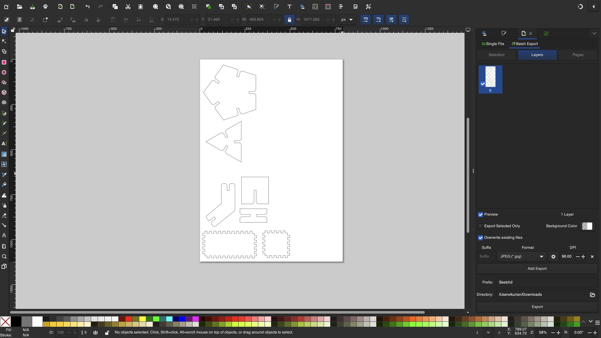 inkscape software
Parametric constraints were used to define slot widths so that kerf and material thickness could be adjusted globally without redesigning parts.
Kerf Test
What is Kerf?
Kerf is the width of material removed by the laser beam.
When laser cuts, it doesn’t cut a zero-thickness line. Instead it burns away a small width of material.
That removed width = Kerf
Why Kerf is Important?
If you design a 10 mm slot, the actual slot must be 10mm + kerf. While cutting, the laser removes material equal to the kerf width. Because material is removed outward from the cut line, the final slot becomes slightly larger.
So joints won’t fit correctly unless kerf is compensated.
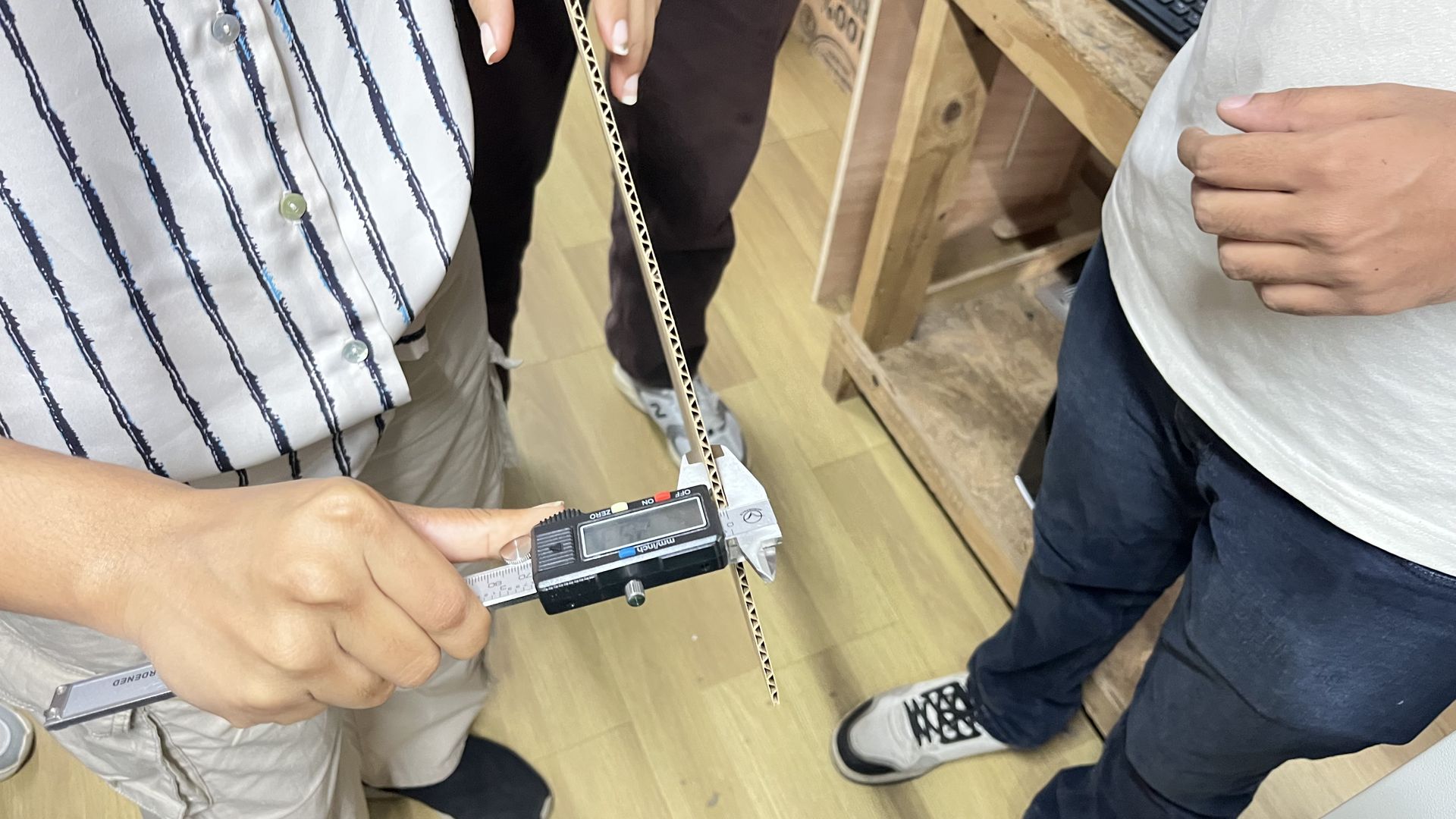
A kerf test was conducted to measure the material removed by the laser during cutting. Cardboard was used as the test material. The cardboard thickness was measured to be 3 mm using Vernier Callipers.
To accurately characterize our laser cutter, we performed kerf tests on three different materials available in our lab:
Cardboard
Wood
Acrylic
The objective of this test was to determine the amount of material removed by the laser beam during cutting and to use this value for press-fit joint design and dimensional compensation.
Methodology
For each material, the following procedure was followed:
1. A test file was created consisting of:
One outer square (40 mm)
One inner square (20 mm)
This vector file was created in Inkscape.
2. The file was sent to the laser cutter using standard cutting settings for that material.
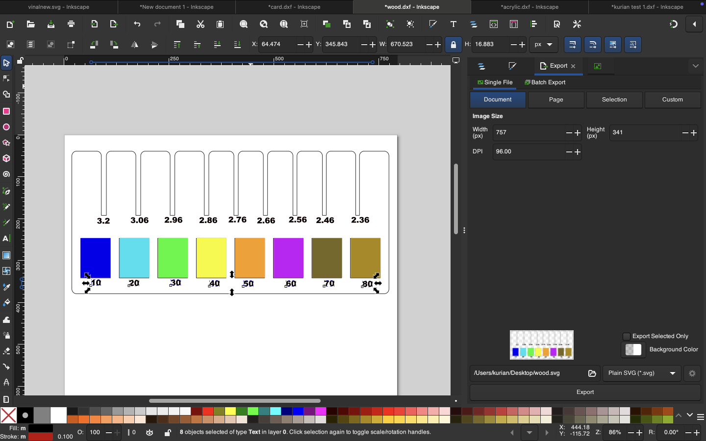
Color Coding for Laser Operations:
Laser operations in Trotec machines are controlled using color-based settings.
The following color assignments were used:
Black fill → Raster engraving
Red stroke (0.1 mm line width) → Vector cutting
It is important to ensure:
Cutting lines are set to hairline thickness (0.1 mm)
Engraving elements use fill (not stroke)
This allows the JobControl software to correctly interpret operations.
Sending the File to the Laser Cutter:
Press Ctrl + P in Inkscape.
Select Trotec Engraver as the printer.
Click Print.
Once the print command is given, the TROTEC JobControl software automatically opens. The design is then transferred directly to the JobControl workspace, where it becomes available for positioning and parameter adjustment before starting the cutting or engraving process.
Inside JobControl, the cursor icon represents the current position of the laser head on the machine bed. The job file is dragged and placed onto the desired snap position within the virtual workspace, matching the actual placement of the material inside the machine. The design is carefully aligned according to the material’s position to ensure accurate cutting or engraving. The connection status indicator confirms that the laser cutter is properly connected and ready for operation.
For each material, the following parameters were configured:
Power (%)
Speed (%)
3. After cutting:
The outer dimension of the inner cut piece was measured.
The inner dimension of the outer frame was measured.
Measurements were taken using a vernier caliper for high accuracy.
4. The difference between these two values gave the total gap created by two laser passes.
5. Since the gap is created by two sides of the laser beam, the kerf value was calculated as:
𝐾𝑒𝑟𝑓=𝑇𝑜𝑡𝑎𝑙 𝐺𝑎𝑝/2
The design was laser cut using the same material, focus, power, and speed settings intended for the final press-fit components.
This was the final output of the kerf test.
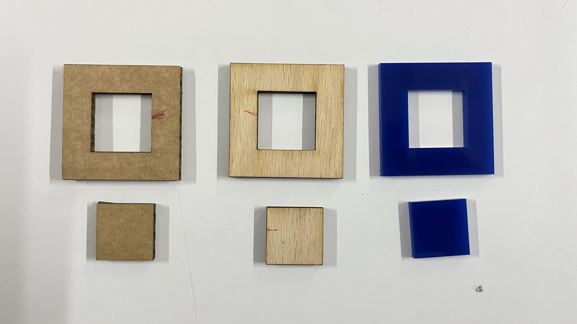
By comparing the designed dimensions with the measured dimensions of the cut pieces, the kerf value was calculated. The effective kerf was found to be approximately
- 0.3 mm for cardboard,
- 0.14 mm for wood and
- 0.1 mm for acrylic.
Conclusion
The kerf value differs for each material and must be measured individually. These values were later used to:
Design press-fit joints
Adjust slot widths
Create parametric construction kits
Determine proper joint clearance
Accurate kerf measurement ensures tighter fits, better structural integrity, and reduced trial-and-error during fabrication.
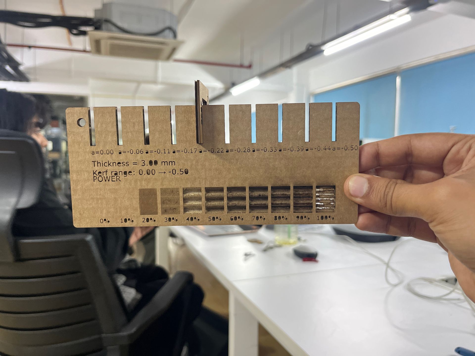
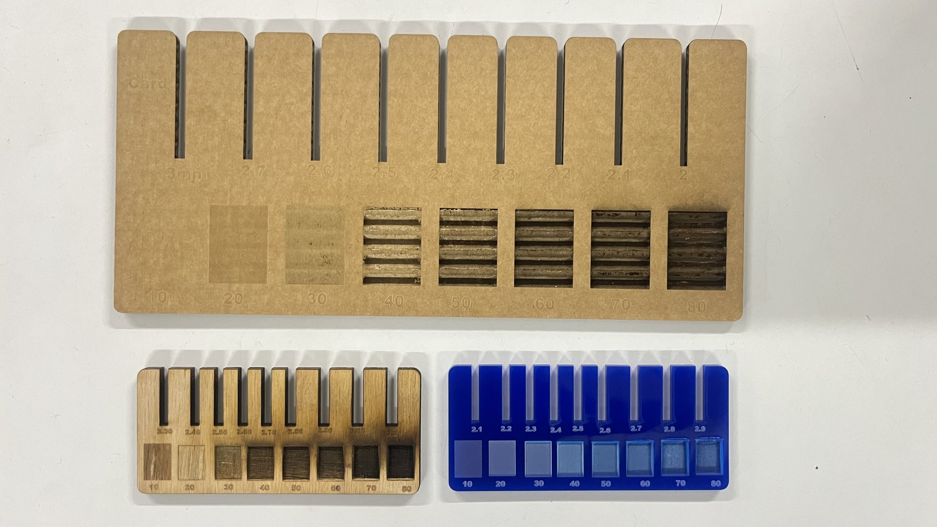
Kerf Measurement Comb
The objective of this assignment was to design and fabricate a parametric kerf-measuring comb using a laser cutter. The comb is used to determine the kerf value of the laser cutter by testing multiple slot widths and identifying the best press-fit for a given material thickness.
Each slot represents a different tolerance, allowing comparison between theoretical and real-world laser cutting results.
Software and Tools Used:
- Autodesk Fusion 360 (Sketch and Parametric Design)
- Laser Cutter
- Calipers (for measuring material thickness)
- Sheet material (Cardboard)
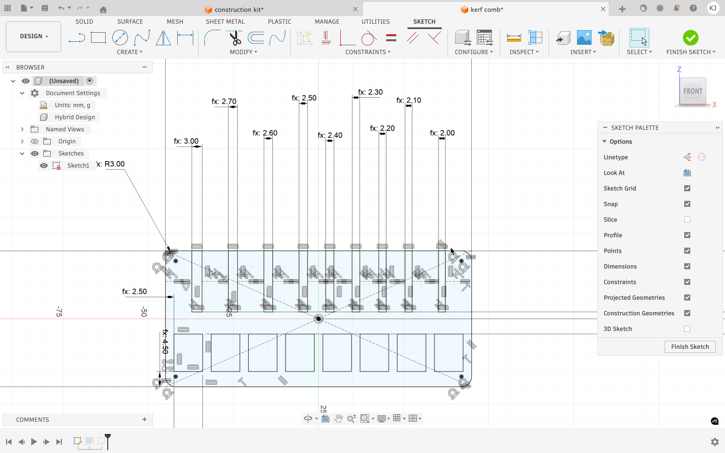
Sketch Design
Fusion 360 was used to create the parametric design. A new sketch was created, and user parameters were defined using the Modify → Change Parameters option. These parameters were used to control the width and height of the rectangular base of the comb.
Step 1: Creating the Base Geometry
A rectangular base was first created to act as the body of the kerf comb. This base holds all the test slots and ensures structural stability during cutting and testing.
Based on the calculated kerf values and measured material thickness, parameters were created in Fusion 360 for dimensions such as:
- Length
- Slot length
- Slot gap
- Jig width
- Slot width
- Material thickness
Step 2: Designing the Reference Slot
The first slot was designed to match the exact material thickness. This slot represents one test joint and is designed to receive a matching material thickness. The slot width was defined parametrically so it could be adjusted later without redrawing the geometry.
Designing the Kerf-Adjusted Slot
The second slot was created by reducing the slot width by the kerf value. This slot represents the expected optimal press-fit and serves as a baseline for evaluating the accuracy of the assumed kerf.
Creating Progressive Tolerance Slots
Additional slots were designed with incrementally reduced widths, each smaller than the previous one by a fixed step. This creates a gradual transition from loose fit to tight fit. Helps visually and physically identify the most accurate press-fit Eliminates the need for repeated test cuts Each slot was derived from the same original geometry to maintain consistency.
Step 3: Parametric Slot Control
The slot width was defined using a parameter that accounts for material thickness and laser kerf. This ensured that any change in kerf or material properties would automatically update the slot geometry throughout the design.
 cardboard design
 wood design
 acrylic design
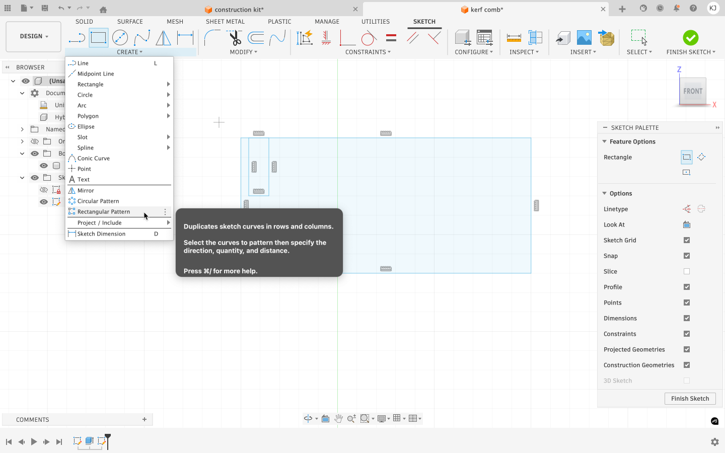
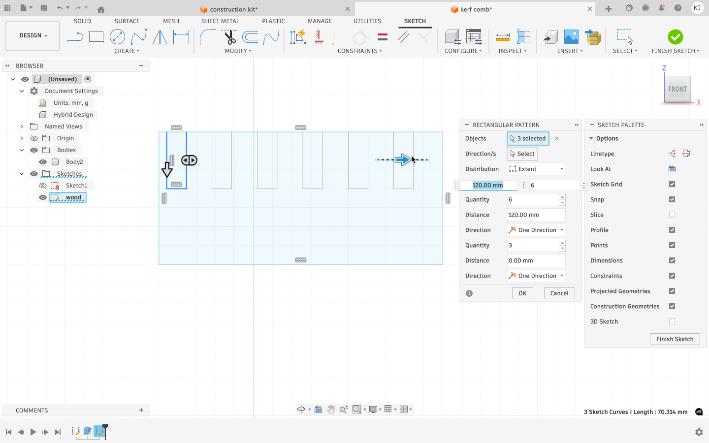
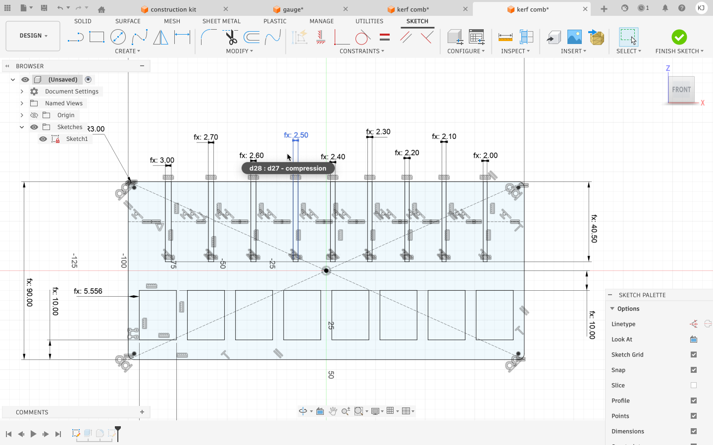
Step 4: Duplicating Slots Using Rectangular Pattern
Instead of manually drawing multiple slots, a Rectangular Pattern tool was used to duplicate the single slot horizontally across the comb. The pattern direction was set along the length of the comb. Multiple instances were generated in a single row. Each slot remained linked to the original sketch, preserving parametric control This approach allowed consistent spacing, alignment, and easy future modifications.
Step 5: Finalizing the Sketch
All sketches were fully constrained to avoid errors during export and fabrication. Unnecessary construction lines were removed, and the design was checked for overlapping or open vectors that could affect laser cutting.
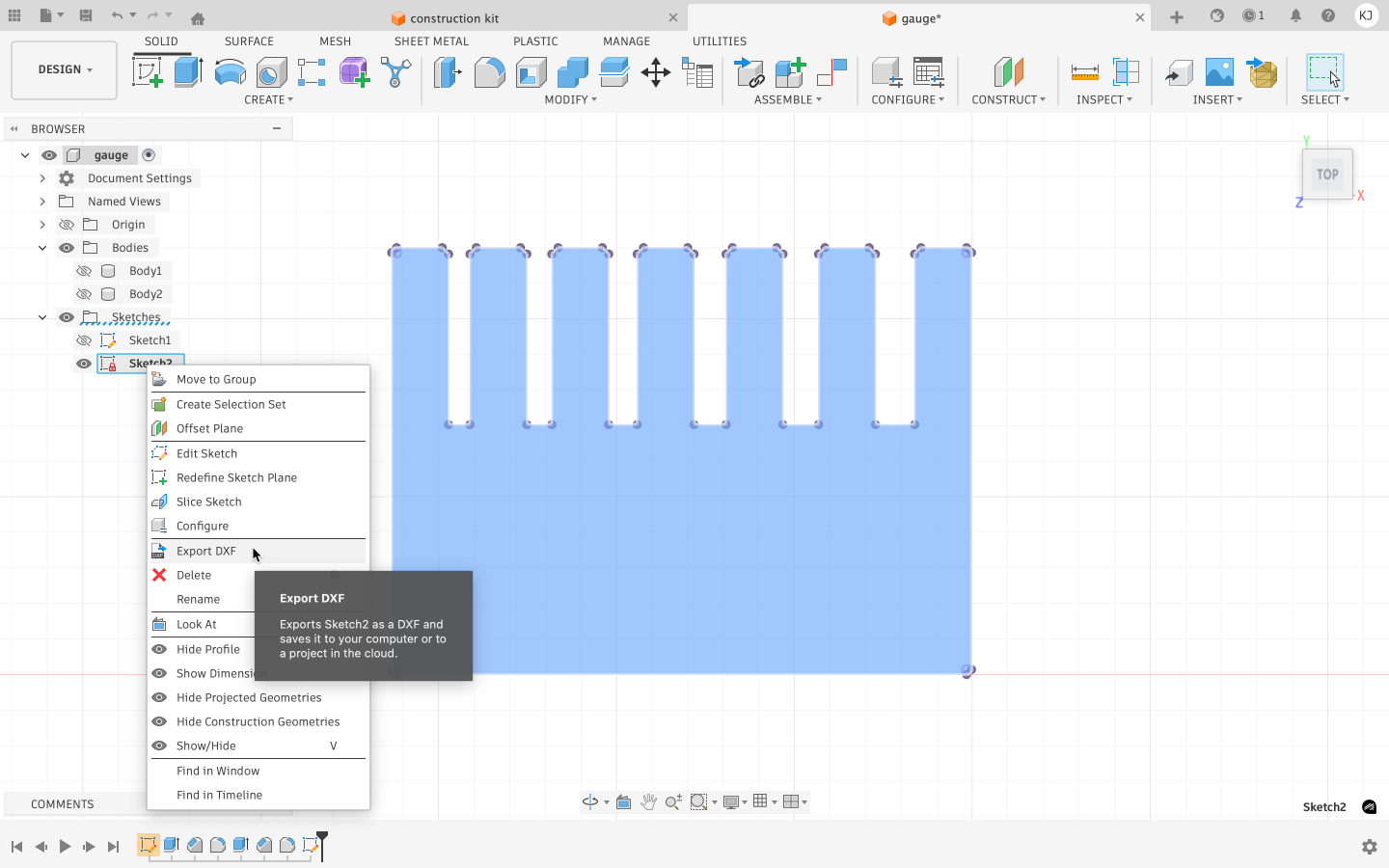
Step 6: Exporting for Laser Cutting
The final sketch was exported in a laser-compatible vector format (SVG/DXF).
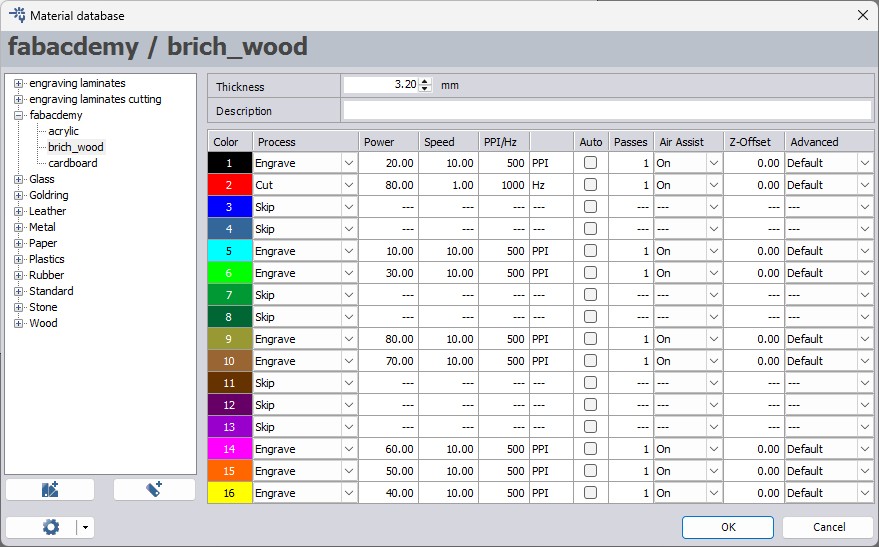
Setting Parameters in TROTEC JobControl:
Inside JobControl, laser parameters were assigned to each color. The machine processes the design elements according to the order defined in the parameter table.
Since using 100% power is not recommended for all machines, deeper engraving was achieved by reducing the speed instead of using full power.
Before cutting, it is important to ensure that the correct material type and thickness are selected in JobControl.
Step 7: Laser Cutting and Testing
Machine Setup and Initialization
Before operating the laser cutter:
Ensure the ambient temperature is between +15°C and +25°C.
Switch on the nearest exhaust vent before starting the machine.
Keep the exhaust running for 15–20 minutes after operation.
Powering On the Machine
- Turn the key switch clockwise.
- Wait for the initialization process:
Internal lights turn on.
Z-axis calibration (moves slightly down and up).
X and Y axes calibration (laser head moves to top-left corner).
- Audible signal indicates completion.
- Turn on the fume extractor and filter manually.
The kerf comb was laser cut using the selected material. After cutting, each slot was tested using a matching piece of material to evaluate the fit, ranging from loose to tight. This physical testing helped identify the most accurate kerf value for future press-fit designs. Outcome The kerf comb provided a quick and reliable method to calibrate laser cutting tolerances. The best-fitting slot was used as a reference for updating kerf values in subsequent parametric designs.
Testing with Different Materials
The same process was repeated for:
- Acrylic
- Wood
- Cardboard
For each material, the parameter values were adjusted in Fusion 360 based on kerf and thickness. The updated file was exported, imported into Inkscape, color-coded appropriately, and then sent to JobControl for cutting.
Through testing, compression values (joint clearance adjustments) were determined for each material. These values were documented in a reference table for future use in designing the parametric construction kit.
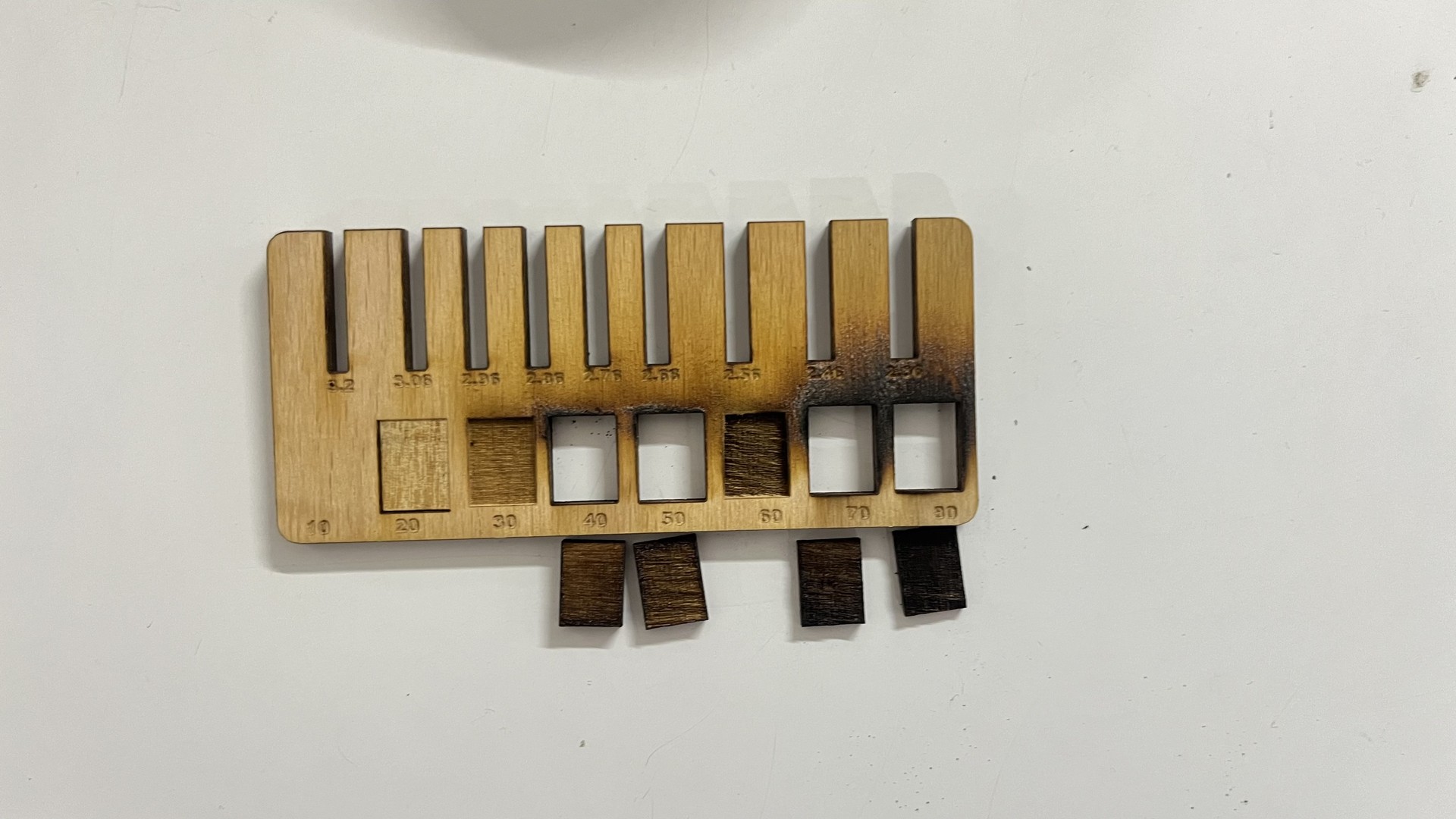
Error During Wood Jig Preparation
While preparing the wood jig for laser cutting, an error occurred in the file setup stage. The slots intended for power testing were mistakenly assigned the color red in Inkscape.
In the TROTEC workflow, red is the standard color used for cutting operations. As a result, instead of being engraved for power testing, those slot areas were fully cut through.
This caused the power testing slots to detach from the main jig body, making the jig unusable for its intended purpose.
The mistake highlighted the importance of carefully verifying color assignments before sending the file to JobControl. Since laser cutters interpret operations based on color mapping, even a small color error can lead to complete material loss.
After identifying the issue, the file was corrected by:
- Ensuring cutting paths were assigned red
- Assigning engraving elements black
- Rechecking the JobControl parameter table before starting the job
The jig was then re-cut successfully with the corrected settings.
Advantages of Laser Cutting
- High precision and accuracy
- Clean cuts with minimal material waste
- Ability to create complex designs and intricate patterns
- No physical contact with material (reduces wear and contamination)
- Fast processing speeds
- Versatility across different materials and thicknesses
Limitations and Considerations
- Material thickness restrictions
- Heat-affected zones and potential warping
- Initial equipment costs
- Safety considerations (eye protection, ventilation)
- Material-specific challenges (reflective metals, certain plastics)
Applications of Laser Cutting
- Manufacturing and prototyping
- Automotive industry
- Aerospace components
- Electronics and circuit boards
- Signage and advertising
- Jewelry and decorative items
- Architectural models
- Medical devices
Conclusion
This project provided valuable hands-on experience with laser cutting and parametric design. We learned how to operate the laser cutter safely, calculate kerf values, and apply those values in CAD modeling to improve fit accuracy.
By designing and testing jigs for acrylic, wood, and cardboard, we understood how material properties affect fit and laser behavior. Parametric modeling allowed us to quickly adapt the design for different materials without redesigning from scratch.
Overall, the process improved our technical understanding, design efficiency, and problem-solving skills while reinforcing the importance of precision in digital fabrication.