INTRODUCTION
This week marks the changing point between my two homes for the Fab Academy program. After lecture this week, I packed up my apartment in Lima and came back to Toronto to spend the Easter weekend with my wife and family before continuing onward to Yokohama for the rest of the program. This is an incredibly exciting week for me, but also an exhausting one. Lima only has a 1 hour time zone difference to Toronto (it was the same time zone before Toronto switched to DST) but I feel the most jet lagged in my life. Between my two trans-continental flights and visits to see my in-laws in Niagara, I've net almost 17,000km of distance this week.
And yet, I still found time to try to learn how to make (almost) anything.
[x] Send a message between two projects
[x] Design, build and connect wired or wireless node(s) with network or bus addresses and a local input and/or output device(s)
RECAP
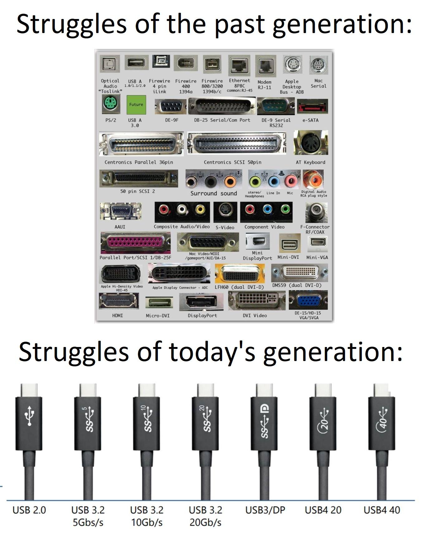
These past three weeks we've been studying a lot about how computers (and microcontrollers) speak to each other. We learned about different ways that machines detect physical changes in our environment, by converting different physical quanta into electrical signals. We also learned about ways to drive those quanta back out into the world using the exact same electrical signals. This week, we bridge the two concepts and review the different ways that our machines (and connected devices, smart or not) speak to each other, and the many ways that humans have come up with clever ways to turn simple binary signals into comprehensible and actionable commands in our incredibly busy technical world.
In learning about these processes over the last 3 weeks, I've taken some time to produce some interactive demonstrations of how these protocols and systems function (with a layer of abstraction/simplification) to aid my own learning (and anyone else reading this!). If you'd like to take a look at some of the other input/output specific demonstrations, head on over to those pages, but I'll be copying a few of them here to this page once again to give context to my assignment this week. I made these demonstrations using a mix of vector graphics (creating SVG paths in Illustrator), implementing some of the existing HTML/CSS of my site, and prompt engineering Gemini to make the skeleton animate with Javascript. Here's the pre-prompt I used to generate each demonstration. You'll also find the individual prompt for each below each demo.

You are an expert front-end developer and web animation specialist. Help me write vanilla JavaSript (not React) to animate several core concepts in electrical engineering for a widget on my website. I will provide you with a prompt that describes the concept as I want to convey it, how the user interacts with it, state machines to consider, the SVG objects and their names, the HTML layout of the site that I've already configured, and some CSS properties of the interactive components. [Insert individual prompt here]
Wired Communication
➔ UART
I have technically already deployed a use of UART in my week 03 assignment, when I programmed and listened to the ATtiny45 and ATtiny412 boards, though with less of an appreciate for how it was working. UART, in a sense, is the most primitive and brute-force method of communication between devices, at least compared to I2C and SPI. Instead of having a clock line that synchronizes the flow of data between hosts, UART requires both hosts to use an agreed upon "baud rate", essentially a frequency to decode the flow of 0s and 1s that usually needs to be set by a human in code or directly with the hardware, a dedicated transmission and receiving line (much like an ethernet cable), and a "start" bit that one device will send to let the other device know they intend to begin sending data. Once a link has been established, the communication between devices is essentially as raw as it gets, sending individual bits down the TX/RX, with little regard for acknowledgement or packet structure, all that's needed is an agreed parity (number of bits sent at a time). It's messy, it's asynchronous, it's legacy, but it's raw and it works for low level debugging and data transfer.
AI Prompt Attribution
➔ I2C
Inter-Integrated Circuit. As we discussed last week, I2C uses two wires to packages every command with a specific hardware address, and it works in both directions, which means it is half-duplex. Output devices can (and should) talk back to the microcontroller to confirm receipt of any instructions.
I2C also solves the problem of running out of pins on your microcontroller by allowing you to run devices on the same bus, because each device will only listen for it's address before reading what's inside the package. Because these devices communicate by pulling the line to ground (0V) rather than pushing voltage out, the bus requires pull-up resistors to keep the default state HIGH.
AI Prompt Attribution
➔ SPI
Serial Peripheral Interface. Again, this works in a similar way to I2C, but instead of addressing individual components in binary, we directly wire them up with something called a "Chip Select" pin for each device. However, instead of using the same SDA line, we have a dedicated talk/receive line, making it "full-duplex".
AI Prompt Attribution
➔ USB
Universal Serial Bus. Certainly the most complicated when it comes to communication but for good reason. USB has a whole consortium surrounding it to dictate the rules and methods that devices are allowed to talk to each other. This allows (for better or for worse) a lot of amazing things to happen over USB, such as transferring huge amounts of data to supply video monitors, high-speed solid state drives, and our handy microcontroller development boards!
I'm going to try to keep things simple in my explanation for brevity (and the fact that I need to go spend time with my in-laws shortly). Before data can even flow via USB, the devices involved need to determine that a device is actually physically connected, and it's more involved than just pulling a pin low. For USB-A, this mostly takes place in software, with a back-and-forth handshake over the D+ and D- lines, but for more complicated specifications like USB-C that have many more data pins, it's possible to tie some of these pins down with resistors to communicate quickly what kind of protocol/data transfer is supported. Once the handshake is formalized, the device is able to identify itself usually with an onboard chip that stores basic information like it's name, the vendor who made it, what kind of interface it is and how much power (if any) it will ask to draw. The host device then assigns a unique identifier or address to that connection and is able to speak to it much in the same way your router will address messages for specific ports over WiFi or Ethernet. The demonstration below goes over the handshake protocol step-by-step in the moments before you hear that new hardware connect sound in Windows after you've plugged something in via USB.
AI Prompt Attribution
Wireless Communication
➔ WiFi
I find myself breaking down the magic that is WiFi (Wireless Fidelity) to my high school students whenever I get the chance. I'll be honest, on paper - it's quite boring to read about, but it really is a modern marvel among other communication protocols that power our world and keep us (for better or for worse) constantly entertained and connected. WiFi itself though has no actual direct link to the "internet" despite what a teenager might be demanding from you upon arrival to a new place. WiFi really is just a smart way to get what the Ethernet protocol achieves sans wires. It communicates over radio waves (specifically 2.4Ghz and 5Ghz) to blast out each 1 and 0 to all of the devices within range.
WiFi enabled devices will listen for their MAC address—a hardware identifier permanently burned into the network card. They are essentially waiting for their physical location to be called out on the local network segment before they start listening to this stream of 1s and 0s. If your MAC address isn't called, the packet of 1s and 0s isn't for you.
To understand how this fits into the broader network stack, it helps to look at the three different levels of addressing (thanks, Henk) and you can think of it as an analogy of sending someone a letter in the mail (where the analog would be sending a packet over a network):
- Hostname (Layer 7): This is a human-readable name, like
laptop.local. Think of this as the actual name of the person receiving a letter. - IP Address (Layer 3): This is a logical address assigned by software to route data across the internet. Think of this as the person's postal address on the envelope.
- MAC Address (Layer 2): This is the physical location on the local network. Think of this as the specific mailbox on your street—it is only relevant for the final few meters of delivery.
The big idea here is that a router isn't shooting an invisible, private laser beam to your device. WiFi is screaming across the entire room, and other devices are just "politely ignoring" anything that doesn't have their specific MAC address on it.
AI Prompt Attribution
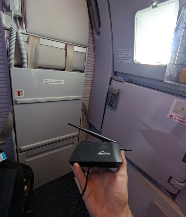
On my flight back from Lima, I thought "Hey, why don't I just pack my router in my carry on bag and use it to try out some of the CircutPython libraries on the plane?". And so I did just that...
We're not quite at the part of the course where we're making API calls, but I wanted to give it a try with a simple Flask server deployed on my laptop so my XIAO ESP32-S3 had something to talk to. The flask server on my computer really only served a single purpose: provide the XIAO with a mock payload of data to work with, everything else would be running entirely on the XIAO.
from flask import Flask, jsonify

app = Flask(__name__)

@app.route('/api/data', methods=['GET'])
def get_data():
    mock_payload = {
        "status": "CONNECTED",
        "flight": "YYZ to HND",
        "message": "Hello from my laptop! This message is sent over WiFi to the XIAO ESP32 from a Flask sever, and then being sent back to my computer through the serial port and into this terminal window!",
        "author": "2026",
        "test": "\u001B[1;5;7m\u001B[48;5;2m#############################\u001B[0m",
        "green-bar": "Kieran Mills (ESAN/Kannai)",
        "sensor_target": 24.5
    }
    return jsonify(mock_payload)

if __name__ == '__main__':
    app.run(host='0.0.0.0', port=5000, debug=True)
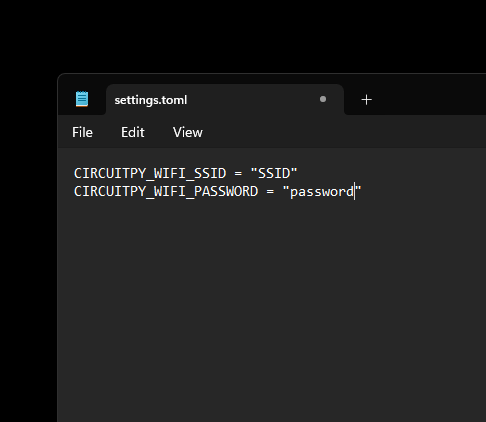
This "server" is run on a local IP address that I can point the XIAO to once I've got everyone on the same network. Once connected, the XIAO will essentially ask for the "mock_payload" object, which is just a JSON formatted chunk of data. I've just got some placeholder text in the script above, and I was trying out some ANSI escape codes to get the output to look fun and colourful in the serial terminal. For the XIAO to be able to connect to my router, I created a file called settings.toml to the root directory of the cricutpython drive with the SSID and password so I could easily change it without editing the python script.
Then we get a script together on the XIAO that tries to make this API request. This utilizes the socketpool and adafruit_requests libraries that utilize the onboard 802.11 antenna the ESP32 has to communicate over WiFi. All of the addressing and package information is handled by these packages. This script makes that API call and then prints what it receives in the serial terminal.
import os
import time
import wifi
import socketpool
import adafruit_requests

print("\n Connecting...")
ssid = os.getenv("CIRCUITPY_WIFI_SSID")
password = os.getenv("CIRCUITPY_WIFI_PASSWORD")
wifi.radio.connect(ssid, password)
print(f"Connected! ESP32 IP: {wifi.radio.ipv4_address}")

LAPTOP_IP = "192.168.0.100" #this changes to whatever your actual IP address is
API_URL = f"http://{LAPTOP_IP}:5000/api/data"

pool = socketpool.SocketPool(wifi.radio)
requests = adafruit_requests.Session(pool)

print(f"\nFetching...")

response = requests.get(API_URL)
json_data = response.json()

print(json_data['test'])
print(json_data['test'])
print(json_data['test'])
print(json_data['test'])

print(f"FAB ACADEMY {json_data['author']}")

print(json_data['message'])
print(f"Flight: {json_data['flight']}")
print(json_data['green-bar'])

print(json_data['test'])
print(json_data['test'])
print(json_data['test'])
print(json_data['test'])

response.close()
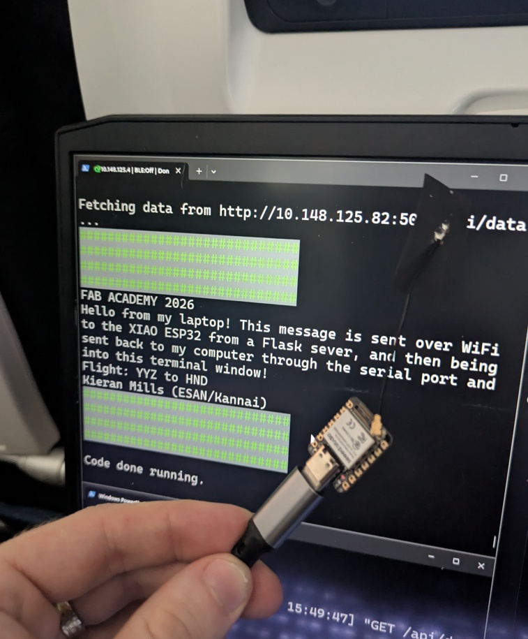
I know that it's kind of a round about way to get these two devices to talk to each other, when they're already attached via USB for the serial monitor read out, but bare with me here, I pulled this off 30,000 feet in the air!
Had some issues getting it working at first and then I realized the XIAO needed the antenna attachment. Sure enough, when I plugged it in, I got the payload in my terminal.
➔ Bluetooth
This works, in a sense, much similar to WiFi (Bluetooth even communicates over the same 2.4Ghz ISM band), but instead of having one central router for devices to be sending/receiving from, each device acts as it's own router, broadcasting messages for intended recipients who have been safely/securely paired. Yes, technically we can do this too with WiFi over adhoc, but Bluetooth uses a different kind of timing structure to make this work, very complex - and like I said - I need to go spend time with my in-laws this weekend.
Data sent over the air is usually encrypted using something called Elliptic Curve Cryptography (ECC) and uses public-private encoding to prevent "man-in-the-middle attacks", where someone can impersonate an access point and get the data you think you're sending to the intended recipient.
AI Prompt Attribution
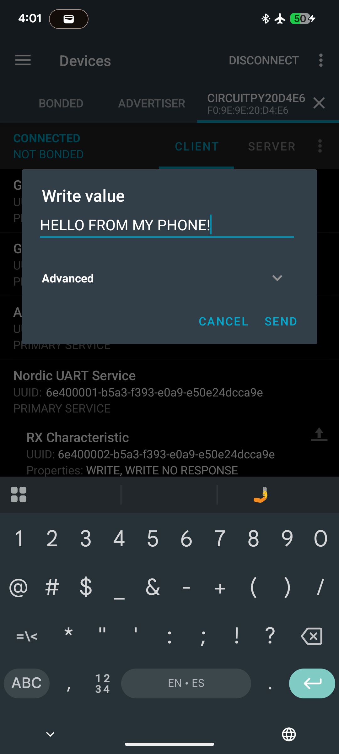
I read online that there's a great app called nRF Connect that does a great job of polling BLE devices that are self-advertising on Android, so I figured I'd give it a go, rather than using my laptop. I put together a script that uses the adafruit_ble libraries to make use of the very same antenna as our last example.
import time
from adafruit_ble import BLERadio
from adafruit_ble.advertising.standard import ProvideServicesAdvertisement
from adafruit_ble.services.nordic import UARTService

print("\n Starting...")

ble = BLERadio()
uart = UARTService()
advertisement = ProvideServicesAdvertisement(uart)

while True:
    print("Advertising BLE...")
    ble.start_advertising(advertisement)

    while not ble.connected:
        time.sleep(0.1)

    print("Phone Connected...")
    ble.stop_advertising()

    while ble.connected:
        #write
        uart.write("HELLO FROM THE XIAO!")

        #read
        if uart.in_waiting:
            incoming = uart.readline().decode("utf-8").strip()
            print(f"BLE Received: {incoming}")

        time.sleep(2)

    print("Disconnected...")
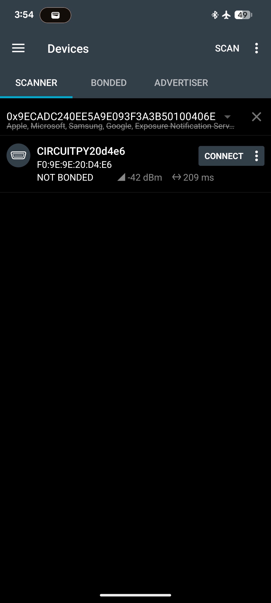
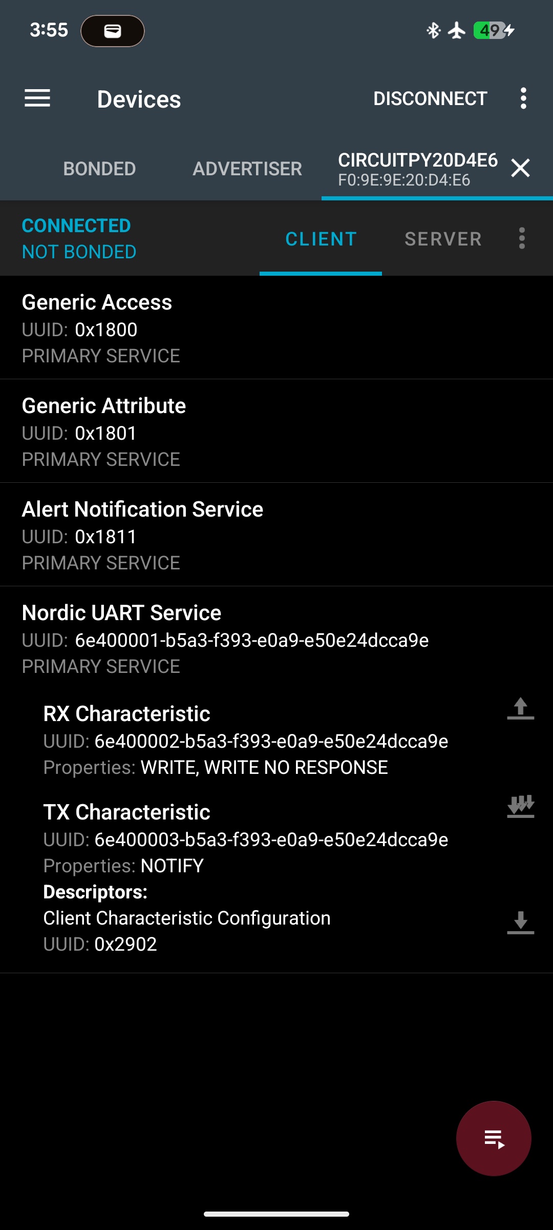
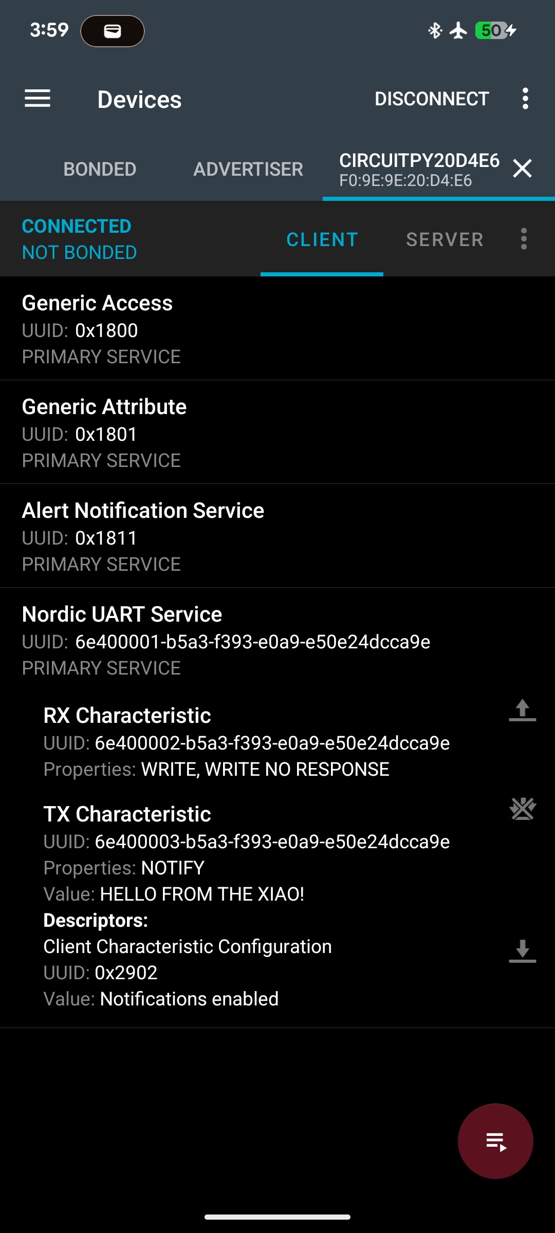
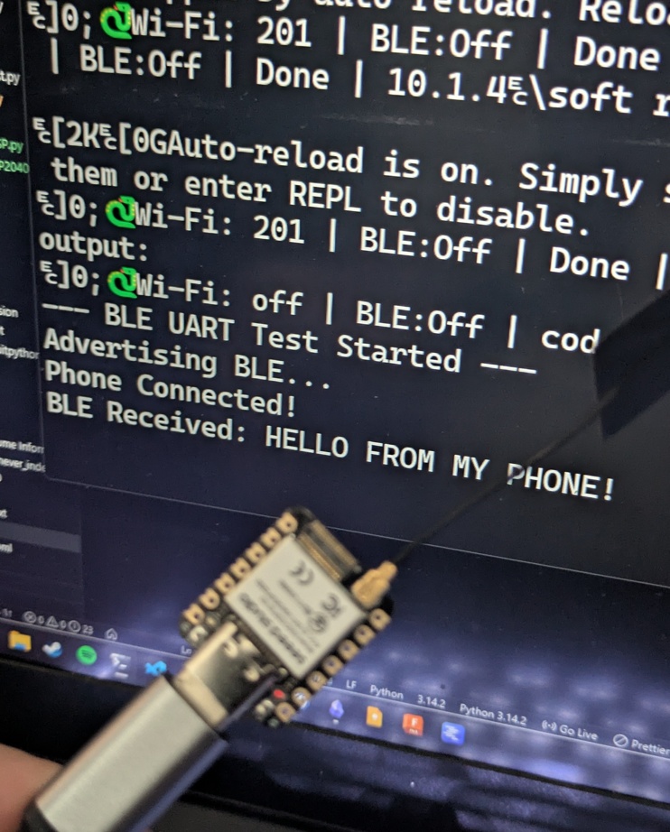
This script broadcasts it's bluetooth name over the air where we're able to find it in the nRF Connect app through a quick scan. Once it makes a successful pair, it sends a string over UART and then continues to listen for any strings that are sent in return, outputting what it gets into the serial terminal.
Putting it All Together
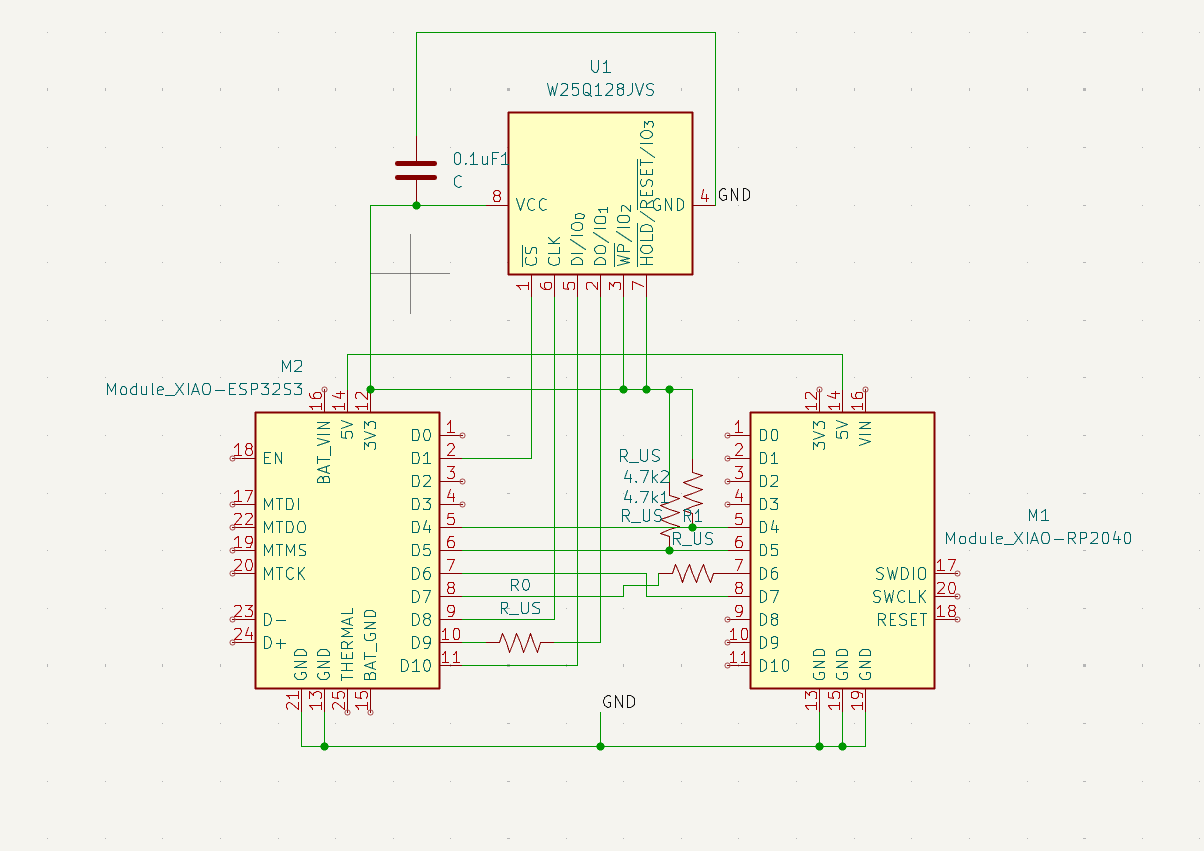
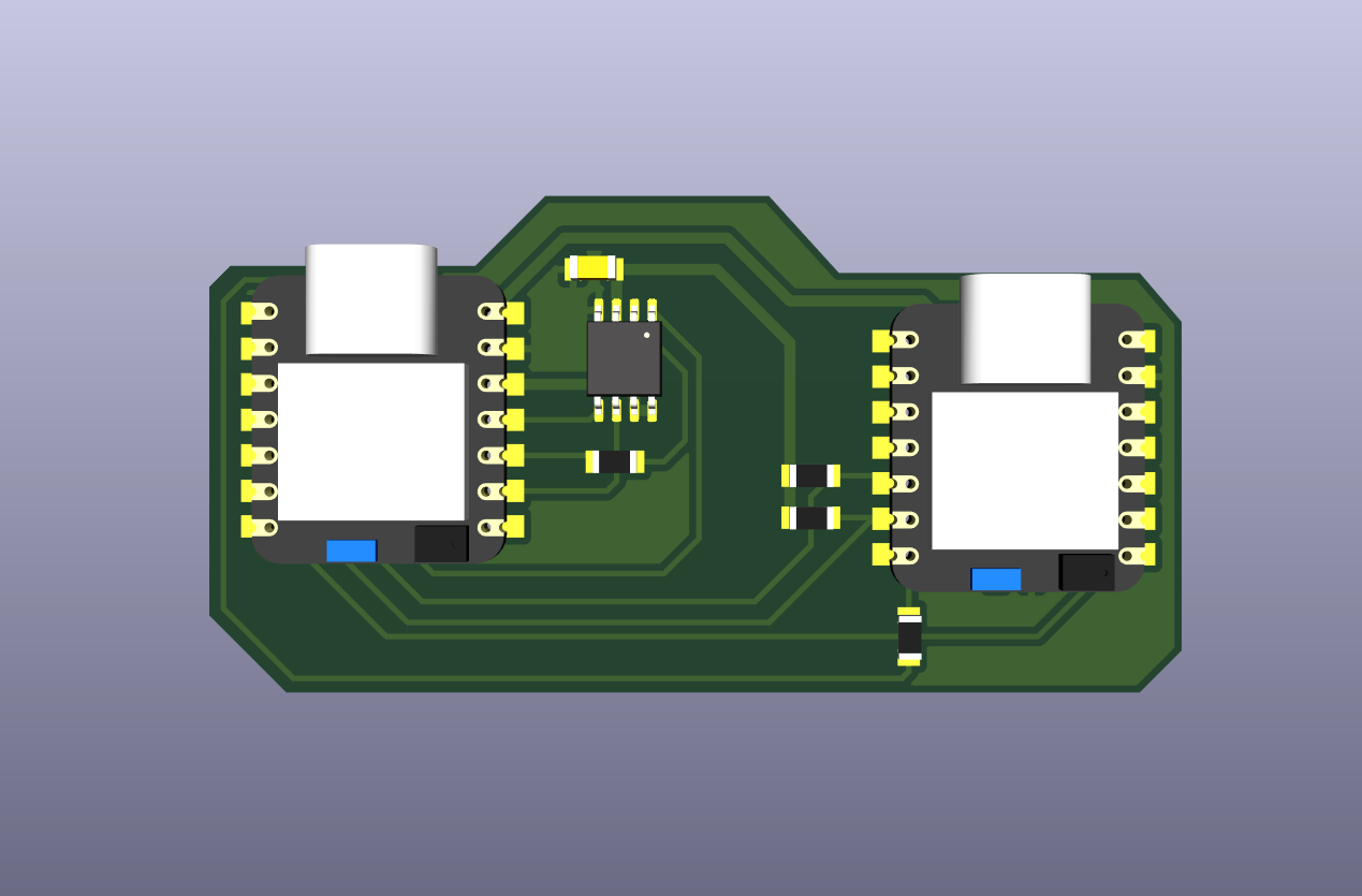
I thought this week would be a good opportunity to continue exploring I2C and SPI communication, as my final project relies heavily on SPI for reading the flash memory off the cartridges and communicating with the display, and I2C to speak to all of the external components that could be added to a cartridge. In my limited capacity aboard a plane (I didn't exactly have a the space to test out every little component), I decided to use another XIAO RP2040 to act as a "dummy" cartridge that could pretend to communicate back information to the main board (ESP32). I used my last day at ESAN to design and mill out a custom board that could accommodate the two boards simultaneously and even one of my W25Q128JVSIQ flash memory chips so I could do some more testing. I decided last minute to switch to UART for simplicity as I would only need to get the RX/TX traces milled.
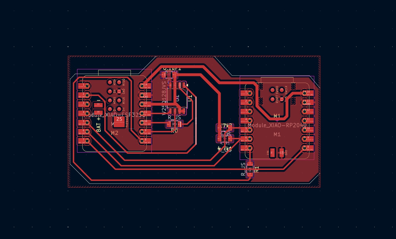
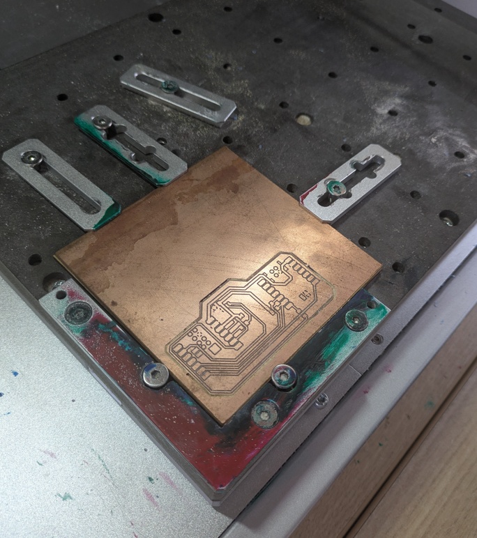
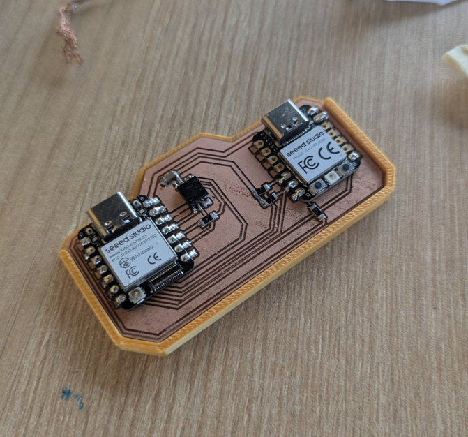
Unfortunately, I couldn't have one final victory over the carvera before leaving ESAN. I was unfortunately humbled in my ambitions to get this all done on my last day. The resulting board has some kind of awful short on the ESP32 side that completely fries whatever board gets soldered down to it. I sadly lost two XIAOs to this little detour, and with an apartment to pack up and a flight to catch in the morning, I decided to cut my losses and concede defeat to the process. They let you take breadboards in your carry on, right?
While waiting for my flight to start boarding, I chipped away at the scripts that both microcontrollers would run. The ESP32 would host a simple HTML webpage that I could pick up by browsing the ESP's IP address on my laptop. This would give me an interface to send and recieve the pings from, seeing as I'm not wiring up much more to these two microcontrollers.
import os
import time
import wifi
import socketpool
import busio
import board
from adafruit_httpserver import Server, Request, Response

print("\n Starting...")

uart = busio.UART(tx=board.D6, rx=board.D7, baudrate=115200, timeout=0.1)

ssid = os.getenv("CIRCUITPY_WIFI_SSID")
password = os.getenv("CIRCUITPY_WIFI_PASSWORD")
print(f"Connecting to {ssid}...")
wifi.radio.connect(ssid, password)
print(f"Connected! http://{wifi.radio.ipv4_address}")

pool = socketpool.SocketPool(wifi.radio)
server = Server(pool, "/static", debug=True)

#html
HTML_PAGE = """
<!DOCTYPE html>
<html>
<head>
    <title>PAK Base Station</title>
    <style>
        body { font-family: sans-serif; text-align: center; margin-top: 50px; background-color: #f4f4f9; }
        button { font-size: 20px; padding: 15px 30px; margin: 10px; border-radius: 8px; border: none; background-color: #007bff; color: white; cursor: pointer; }
        button:hover { background-color: #0056b3; }
    </style>
</head>
<body>
    <h1>PAK Wireless Command Center</h1>
    <p>Click a button to send a UART command to the RP2040.</p>

    <a href="/command/ping"><button>Send "PING"</button></a>
    <a href="/command/status"><button>Request "STATUS"</button></a>
</body>
</html>
"""
@server.route("/")
def base(request: Request):
    return Response(request, body=HTML_PAGE, content_type="text/html")

@server.route("/command/<cmd>")
def send_command(request: Request, cmd: str):
    print(f"Browser clicked: {cmd}")
    uart.write(bytes(f"{cmd.upper()}\n", "utf-8"))
    success_html = f"<h2>Sent '{cmd.upper()}' over UART!</h2><a href='/'>Go Back</a>"
    return Response(request, body=success_html, content_type="text/html")

server.start(str(wifi.radio.ipv4_address))

while True:
    server.poll()
    if uart.in_waiting:
        reply = uart.readline()
        if reply:
            print(f"RP2040 Replied: {reply.decode('utf-8').strip()}")

            time.sleep(0.01)
The ESP and RP2040 will communicate at 115200 baud. Reminder that you have to switch the RX and TX (the ESP's TX becomes the RP2040's RX and vice-versa). The ESP waits for a command from the web server, which is browsed on my laptop over WiFi, before sending a command to the RP2040. We can also ask it to poll the RP2040 from the web server using a simple python script loaded up on the RP2040 itself.
import board
import busio
import time

uart = busio.UART(tx=board.D6, rx=board.D7, baudrate=115200, timeout=0.1)

print("Listening...")

while True:
    if uart.in_waiting:
        data = uart.readline()
        if data:
            message = data.decode('utf-8').strip()
            print(f"Received Command: {message}")

            if message == "PING":
                response = b"PONG\n"

            uart.write(response)
            print("Response sent.")

    time.sleep(0.1)
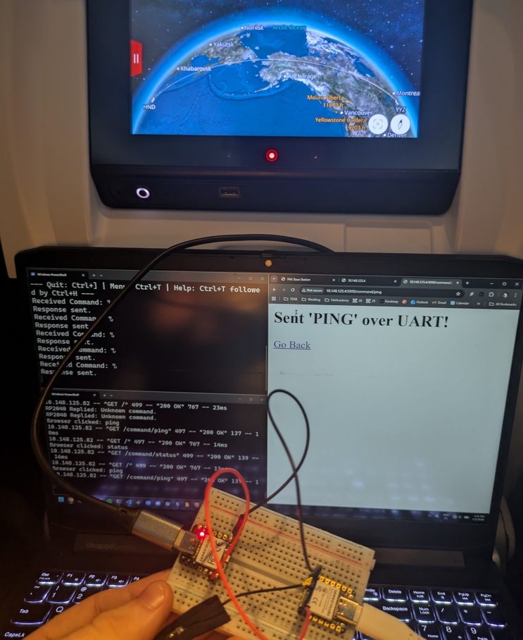
I connected the ESP to the USB power coming from the seat (so I could fully test out the fact that it was running without a tether) and hooked up the RP2040 via USB and started listening over serial. And the result is something that probably looked a little sketchy to my fellow seatmates aboard the plane. It didn't help that I had a middle seat, sandwiched between two strangers, but it made for some great conversation about my journey and what I've been learning at Fab Academy!
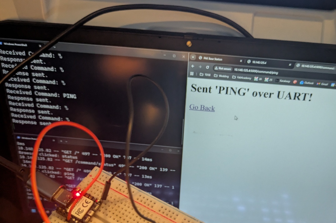
My home soldering iron in Toronto died on me (go figure) and I wasn't able to get pin headers installed on the XIAOs before takeoff, so I bodged them with some dupont connectors which made for a pretty shoddy connection. It took a couple tries to get this right, so as soon as I saw "PING" show up in the terminal of the RP2040, coming from the ESP, I grabbed my picture and called it a day (or whatever time my brain thought it was on my 13 hour flight). I learned a lot this week, even with all the jetlag.
Conclusion
This week was a literal trek, (17,000 kilometers to be precise) and for whatever reason, I spent my last day at ESAN thinking I could go into this assignment expecting to rely entirely on a custom milled carrier board, and I was quickly humbled when a short on that board ended up frying two of my microcontrollers right before I had to pack up my apartment. Despite the setback, a simple bodge of jumper wires allowed me to actually pull off the assignment requirements in the air. I learned a ton about the low-level nuances of the different protocols we're studying and added more interactive demonstrations to my site! A successful transition week, for sure.
See you soon, Yokohama!