8. Electronics Production

Assignments and Assessment this week
Group assignment:
Characterize the design rules for your in-house PCB production process: document the settings for your machine. Document the workflow for sending a PCB to a boardhouse Document your work to the group work page and reflect on your individual page what you learned
Individual assignment:
Make and test a microcontroller development board that you designed
Learning outcomes
Describe the process of tool-path generation, milling/laser engraving, stuffing, de-bugging and programming Demonstrate correct workflows and identify areas for improvement if required
Have you answered these questions?
Linked to the group assignment page Documented how you made the toolpath Documented how you made (milled, stuffed, soldered) the board Documented that your board is functional Explained any problems and how you fixed them Uploaded your source code Included a ‘hero shot’ of your board
Group Assignment
Here is a group assignment page
milling PCB
This weekend was spent battling with SVG files. I finished the cutting just in time and did the soldering after getting home. However, it didn’t work as planned right away. That’s because the resistor I brought home was 499kΩ. I had to re-solder the resistor.
Kicad
Out put GerBer to JLCPCB
gerber2png With Safari, the zip file was unzipped and downloaded, preventing me from successfully installing it into KIcad. With Chrome, the zip file downloaded correctly and the installation worked properly.
Prot SVG File F_Cu EdgeCuts B_CU
View & Share Electronic Designs Online
Electronic component search engine OctoPart
Mods
select mill and add files

outputfils ON and xyz=0

can use mill 10 mil flat(0.254mm) 1/64 flat(0.3969mm) 1/32 flat(0.7938mm) 1/16 flat(1.5875mm)
60°#501 V-vit 40°#502 V-vit
Endmill
Titan USA TC10101 1/64”(0.3969mm) size bit SE 2FL EM |||| | :— | :— | :— | |Cutter Diameter |0.0156” (1/64”)|0.3969mm |Shank Diameter |0.1250” (1/8”)|3.1750mm |Length of Cut (LOC)|0.0313”(1/32”)| 0.7938 mm |Overall Length (OAL)|1.5000” (1-1/2”)|38.1mm |Flutes |2|- |Profile |Square|- |Coating |ALTIN|- |Catalog Page |31|-
Titan USA TC10102 1/32”(0.7938mm) size bit SE 2FL |||| | :— | :— | :— | |Cutter Diameter |0.0313” (1/32”)|0.7938mm |Shank Diameter |0.1250” (1/8”)|3.1750mm |Length of Cut (LOC)|0.1250” (1/8”)|3.1750mm |Overall Length (OAL)|1.5000” (1-1/2”)|38.1mm |Flutes |2|- |Profile |Square|- |Coating |ALTIN|- |Catalog Page |31|-
inch to metric
1 mil (thou) = 1/1000 inch = 25.4/1000 mm (0.0254mm)= 25.4 μm
| Fraction (inch) | Decimal (inch) | Metric (mm) |
|---|---|---|
| 1/256 | 0.0039 | 0.0992 |
| 1/128 | 0.0078 | 0.1984 |
| 3/256 | 0.1172 | 0.2977 |
| 1/64 | 0.0156 | 0.3969 |
| 1/32 | 0.0313 | 0.7938 |
| 3/64 | 0.0469 | 1.1906 |
| 1/16 | 0.0625 | 1.5875 |
| 5/64 | 0.0781 | 1.9844 |
| 3/32 | 0.0938 | 2.3813 |
| 7/64 | 0.1094 | 2.7781 |
| 1/8 | 0.1250 | 3.1750 |
| 3/16 | 0.1875 | 4.7625 |
| 1/4 | 0.2500 | 6.3500 |
| 5/16 | 0.3125 | 7.9375 |
| 3/8 | 0.3750 | 9.5250 |
| 7/16 | 0.4375 | 11.1125 |
| 1/2 | 0.5000 | 12.7000 |
| 9/16 | 0.5625 | 14.2875 |
| 5/8 | 0.6250 | 15.8750 |
| 11/16 | 0.6875 | 17.4625 |
| 3/4 | 0.7500 | 19.0500 |
| 13/16 | 0.8125 | 20.6375 |
| 7/8 | 0.8750 | 22.2250 |
| 15/16 | 0.9375 | 23.8125 |
| 1 | 1.0000 | 25.4000 |
| Fraction (inch) | Decimal (inch) | Metric (mm) |
|---|---|---|
| 1/256 | 0.0039 | 0.0992 |
| 1/128 | 0.0078 | 0.1984 |
| 3/256 | 0.1172 | 0.2977 |
| 1/64 | 0.0156 | 0.3969 |
| 3/128 | 0.02344 | 0.5953 |
| 1/32 | 0.0313 | 0.7938 |
| 5/128 | 0.03906 | 0.9922 |
| 3/64 | 0.0469 | 1.1906 |
| 7/128 | 0.05469 | 1.3891 |
| 1/16 | 0.0625 | 1.5875 |
| 5/64 | 0.0781 | 1.9844 |
| 3/32 | 0.0938 | 2.3813 |
| 7/64 | 0.1094 | 2.7781 |
| 1/8 | 0.1250 | 3.1750 |
Vpanel
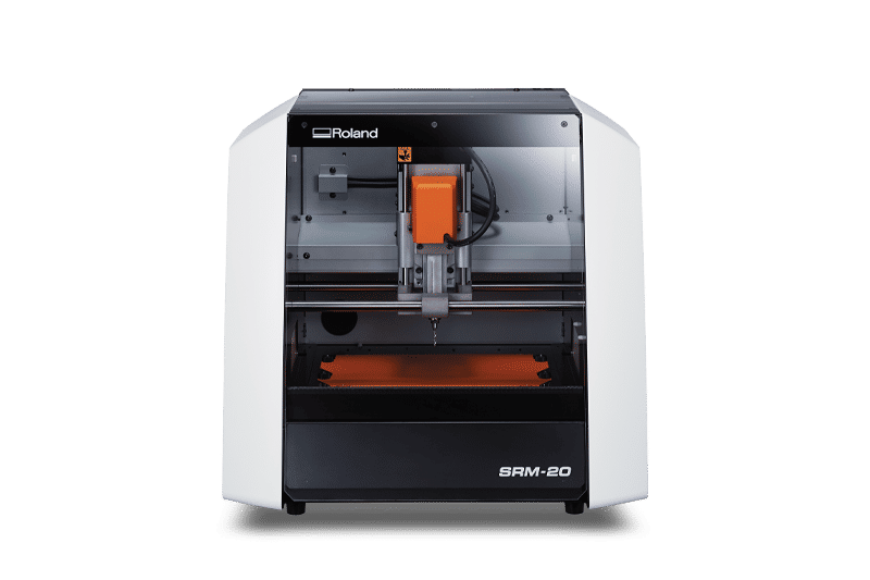
Roland download senter VPanel for SRM-20
SRM-20
Creening PCB
wash
In the case of FR1, small bridges can be easily removed by heating them with a soldering iron. Do it at the same time as soldering.
Soldering
First, I attached the chip. (I was working late at night and my brain wasn’t functioning properly, so I didn’t check the chip number.) Then I attached the socket. For the Xiao part, I bent the socket’s pins alternately, trimmed the ends slightly, and soldered them in place. For the surrounding area, I split a Janome circuit board in half, used it as a base to lift the socket, and temporarily soldered it. After that, I removed the Janome circuit board and performed the final soldering.
Debug
Not work LED
The LED wouldn’t light up.
Even after checking the orientation with a multimeter, it still wouldn’t light up.
I measured the forward voltage (Vf) and it was 1.6V, but when I applied 5V, it only output 1.4V.
The reason was that I had used the wrong value of resistor.
I needed around 500Ω, but I had picked up a chip labeled “499” from a shelf without looking carefully. 4993 = 499kΩ!!
I needed 499Ω, but I didn’t have any on hand.
However, I happened to have 0603-size 470Ω and 2.2kΩ resistors.
I changed 4993 to 470Ω and 2201.

It worked!
arduino test program
int SW_PIN = 26;//rp2040
//int SW_PIN = 2;//ESP32C3
int LED_PIN = 3;//rp2040
//int LED_PIN = 10;//ESP32C3

void setup(){
  Serial.begin(115200);
  pinMode(SW_PIN,INPUT_PULLUP);
  pinMode(LED_PIN,OUTPUT);
  delay(100);
}

void loop(){
  if(digitalRead(SW_PIN) == LOW){
    digitalWrite(LED_PIN,HIGH);
    Serial.println("LED HIGH");
    delay(100);
  }else{
    digitalWrite(LED_PIN,LOW);
    Serial.println("LED LOW");
    delay(100);
  }
}