4. Embedded Programming

Assignments and Assessment this week
Group assignment:
- Demonstrate and compare the toolchains and development workflows for available embedded architectures
- Document your work to the group work page and reflect on your individual page what you learned
Individual assignment:
- Browse through the datasheet for a microcontroller
- Write and test a program for an embedded system using a microcontroller to interact (with local input &/or output devices) and communicate (with remote wired or wireless connections)
Learning outcomes
- Implement programming protocols.
Have you answered these questions?
- Linked to the group assignment page
- Browsed and documented some information from a microcontroller’s datasheet
- Programmed a board to interact and communicate
- Described the programming process(es) you used
- Included your source code
- Included ‘hero shot(s)’
Group Assignment
Here is a group assignment page
Research
What is a computer
## What is a computer The personal computers (PCs) that you are likely familiar with are called von Neumann computers, and have the following elements: A stored-program system in which the calculation procedures (programs) and data to be executed are stored together in the main memory (RAM). Sequential processing in which the CPU reads instructions from the RAM one by one in order, and decodes and executes them. The hardware consists of a CPU (control device/arithmetic unit), memory devices (main memory RAM, auxiliary memory ROM), and peripheral devices (input devices/output devices). ### Hardware These are the components necessary for a personal computer (PC) to function, connected via a motherboard. In desktop PCs, they are housed in a case, while in laptop PCs, they are installed together with peripheral devices. #### Central Processing Unit (CPU) The brain of the PC, processing all instructions and performing calculations. #### Motherboard The main circuit board that connects all components. Memory ##### Random Access Memory (RAM) This is where data used by the PC is temporarily stored; data is lost when the power is turned off. Commonly referred to as "memory" in Japan. ##### Read Only Memory (ROM) This is where data used by the PC is stored long-term; data is retained even when the power is turned off. Commonly referred to as "storage" in Japan. The types are introduced below, chronologically. ###### Punch cards, paper tape Very early devices that record data by punching holes in paper. No longer in use. ###### Magnetic tape (open reel, videotape) A very old type of device, faster and with larger capacity than paper tape. ###### FDD (Floppy Disk Drive) An old-fashioned device, an early device that used a disk format. It is now largely obsolete and rarely seen. ###### Optical Disk (CD/DVD/BD) Popular as a higher-capacity medium than FDD. It is rarely seen anymore. ###### Hard Disk Drive (HDD) A traditional high-capacity storage device that uses a rotating disk and reads magnetic data. ###### Solid State Drive (SSD) High-speed storage using flash memory chips. ###### m.2 SSD A small-form-factor SSD that connects directly to the motherboard via a slot. ##### Graphics Processing Unit (GPU) A dedicated processor that handles image rendering and video output to the display. ##### Power Supply A device that provides the necessary electricity for all components. Without it, the computer would never function. #### Peripherals External devices that connect to a computer to facilitate operation or provide additional functionality. ##### Input Device ###### Keyboard The primary input device for entering text and commands. ###### Mouse A pointing device for navigating a graphical interface. ##### Output Device ###### Display/Monitor A screen that visually displays information processed by a computer. #### Software/OS (Operating System) An OS is system software that manages hardware and provides a foundation for running other software. ##### Windows A widely used commercial operating system developed by Microsoft. ##### macOS An operating system developed by Apple for Macintosh computers. ##### Unix/BSD/Linux A family of operating systems and clones known for their stability, security, and use in server and development environments.What is a microcomputer
-
z80
-
pic
-
H8
-
attyny (atmega328p)
-
RP2040
- ESP32
Evaluation Board
-
arduino This is an introductory microcontroller for embedded programming, with the ATMEGA328P-PU as its core. With this, you can program an LED to blink, which is the first step, just like programming HELLO, Wold. The circuit was simple enough that it was easy to build yourself, but the latest version has become more difficult to build yourself.
-
micro:bit A recommended board for beginners that even elementary school students can use
-
Raspberry Pi Pico
-
M5Stack A cool evaluation board with a screen. The specs are high, just like ESP32.
-
Xiao The smallest readily available evaluation board I’ve come across
-
(Raspberry pi) This is a one board computer
Programming Xiao with Arduino
First, I looked up the datasheets for the ESP32C3 and RP2040 Xiao boards and summarized them briefly.
| Parameter | Seeed Studio XIAO ESP32-C3 | Seeed Studio XIAO RP2040 |
|---|---|---|
| Processor | ESP32-C3 (RISC-V single-core up to 160 MHz) | RP2040 (Dual Cortex M0+ up to 133 MHz) |
| Memory | 400KB SRAM / 4MB Flash | 264KB SRAM / 2MB Flash |
| Wireless | Wi-Fi 2.4GHz, BLE 5.0 / Mesh | N/A |
| Interface | 1xUART, 1xIIC, 1xSPI, 11xGPIO(PWM), 4xADC | 1xUART, 1xIIC, 1xSPI, 11xPWM, 11xDigital, 4xAnalog |
| Onboard | Reset, Boot Button | User LED(3C), Power LED, RGB LED, Reset, Boot |
| Dimensions | 21 x 17.8mm | 21 x 17.8mm |
| Power (Input) | 5V (VIN) / 3.7V (BAT) | 5V (Type-C) / 5V (BAT) |
| Deep Sleep | 44 μA | N/A |
| Working Temp. | -40°C ~ 85°C | -20°C ~ 70°C |
| Software | Arduino, MicroPython, etc. | Arduino, MicroPython, CircuitPython, Rust, etc. |


For the group assignment, I programmed the Xiao ESP32C3 using MicroPython, so for the individual assignment, I decided to program it using the familiar Arduino IDE.
setting
However, my Arduino IDE was version 1.8.x so I installed the 2.0.x version and started by setting up the environment. Download ArduinoIDE 2.0
After downloading, I launched the app and entered the following URL into the Additional Boards Manager URLs in Preferences, otherwise I would not be able to use either the ESP32 or the RP2040.
open the arduino ide

select Preferences

inport URL

https://files.seeedstudio.com/arduino/package_seeeduino_boards_index.json
https://raw.githubusercontent.com/espressif/arduino-esp32/gh-pages/package_esp32_index.json
https://sandeepmistry.github.io/arduino-nRF5/package_nRF5_boards_index.json
copy and paste it

inport esp32 and raspberrypipico

Connect the Xaio ESP32C3 to your PC. Once connected, set up the board and port in the Arduino IDE. Select the Xaio ESP32C3 as the board, and since the ports are different for Windows and Mac, select the port that was added when you connected it. At this time, it is best to set up the USB device only as Xaio ESP32C3, as this will make it easier to configure the port.


programing
Once the configuration is complete, write the following program in the IDE.

int SW_PIN = 4;
int LED_PIN = 5;

void setup(){
  Serial.begin(115200);
  pinMode(SW_PIN,INPUT_PULLUP);
  pinMode(LED_PIN,OUTPUT);
  delay(100);
}

void loop(){
  if(digitalRead(SW_PIN) == LOW){
    digitalWrite(LED_PIN,HIGH);
    Serial.println("LED HIGH");
    delay(100);
  }else{
    digitalWrite(LED_PIN,LOW);
    Serial.println("LED LOW");
    delay(100);
  }
}
Once you’ve finished writing, press the “upload” button to upload. Once the compilation is complete, writing will begin, but if any errors occur along the way, correct them as they occur. Also, since we’ll be using the serial monitor this time, click the magnifying glass icon in the upper right corner and set the baud rate to match the one set in Serial.begin.

Xiao with the program written in
 When you press the switch button, it lights up and sends LED HIGH to the serial monitor.

LED
Do not connect an LED to a power source by itself. It will glow brightly for a moment and then die. To prevent this, limit the current that flows. The forward current at which an LED performs best is generally said to be around 20mA. Let’s consider a circuit for lighting a red LED rated at 1.8V, 20mA, using a Xiao3.3V. When applying a voltage of 2.1V to the LED, the Xiao outputs 3.3V, so the voltage $$ 3.3V - 1.8V = 1.5V $$ must be dissipated somewhere. Therefore, a resistor is connected to apply voltage. (A constant current diode can also be used.) Next, use Ohm’s law to calculate the value of the resistor to connect to set the current through the LED to 20mA. The resistance value is $$ 1.5V ÷ 0.02A = 75Ω $$ (Note: 1A = 1000mA, so 20mA = 0.02A)
switch
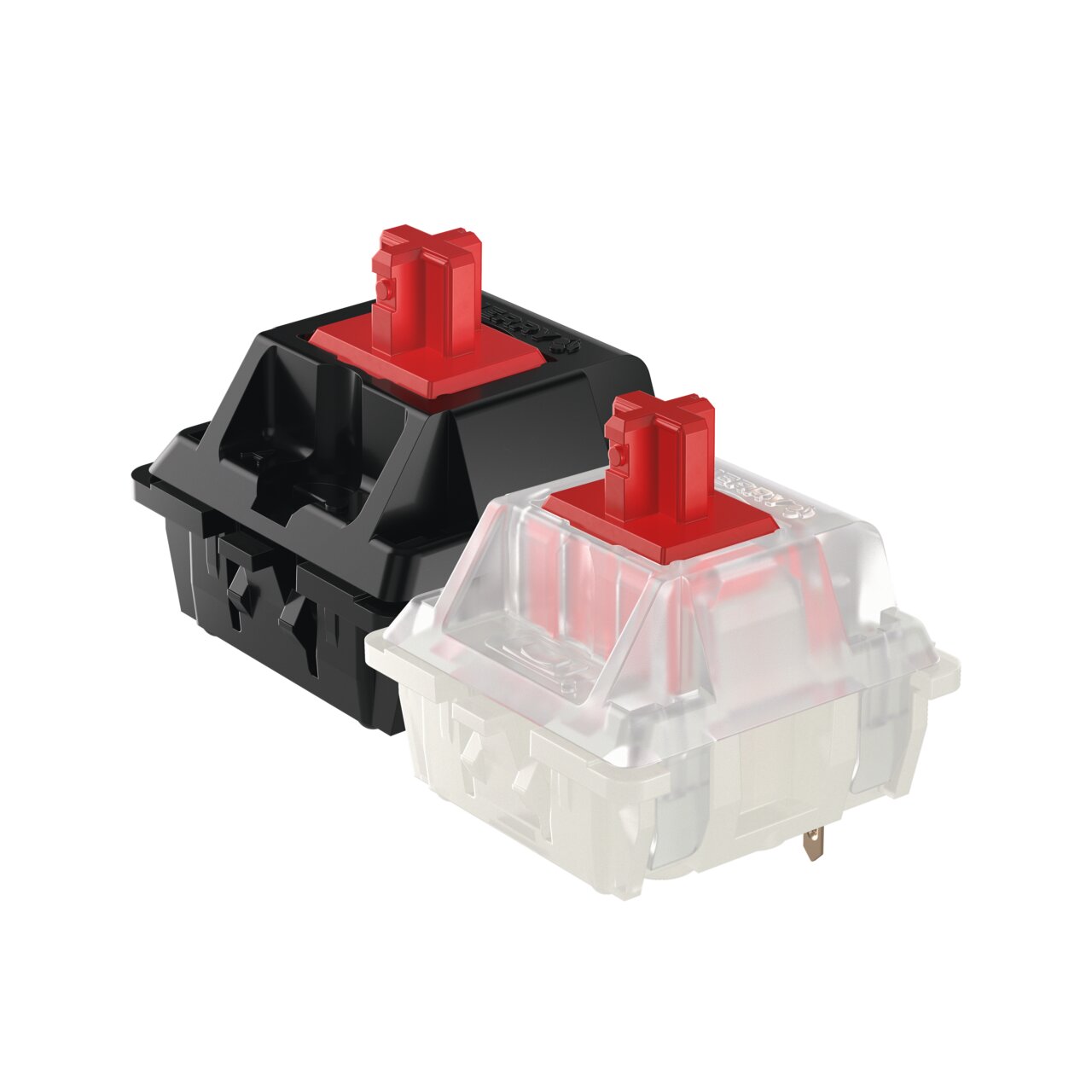
here are many types of switches. Not only “tactile switches,” but also the mice and keyboards you use today contain switches. Keyboards often used “cherry mx” switches, but now they often use other types. Since I thought I could use a “cherry mx” switch and a switch with an LED built in called a “Schadow” or “PB86,” I created a circuit that lights up an LED when the switch is pressed.
tactile switches

cherry mx key switch
 by
cherry mx
by
cherry mx
Schadow PB86
 by adafruit.com
 by John Park
Structure and processing of microcomputers
N.O. is a contact that is normally open (circuit broken) and closes (circuit connected) when pressed, while N.C. is the opposite, a contact that is normally closed (circuit connected) and opens (circuit broken) when pressed. Also, the pull-up resistor is not connected because an internal pull-up is used.
Breadboard.
A convenient board that allows you to assemble circuits without soldering. It’s particularly useful when rapidly changing components during prototyping, but can be a pain as the contacts can rust and high frequency circuits can be prone to noise. It may be easier than wire or wrapping. Electrically, many have horizontal power lines connected together, which are separate from the vertical component lines. Some smaller ones only have component lines. That’s what I used this time.

conect cherry mx key switch and LED by xiao

When I put the keycap on, it was hard to see the glowing part, so I removed it.

push switch and blink LED

conect PB86 and LED

push switch and blink LED
