Week 7 — Computer-controlled machining
Group assignment for this week is on the Chaihuo Week 7 group assignment page. The rest of this page is my individual work.
Individual assignment
My individual project was a flat-pack little chair, designed and milled on the lab’s large wood CNC. The finished piece is small, but the job uses a full sheet on the TC1325B router and press-fit slots sized to measured board thickness. Design was in Fusion 360; toolpaths came from Mastercam X6 at the CAM station.
Design: flat-pack chair in Fusion 360
I wanted something I could actually assemble at the end of the week, not just a test bracket. A miniature chair still forces the usual CNC furniture problems: nesting parts on one panel, sizing slots to measured stock, and leaving clearance for a round bit in square corners.
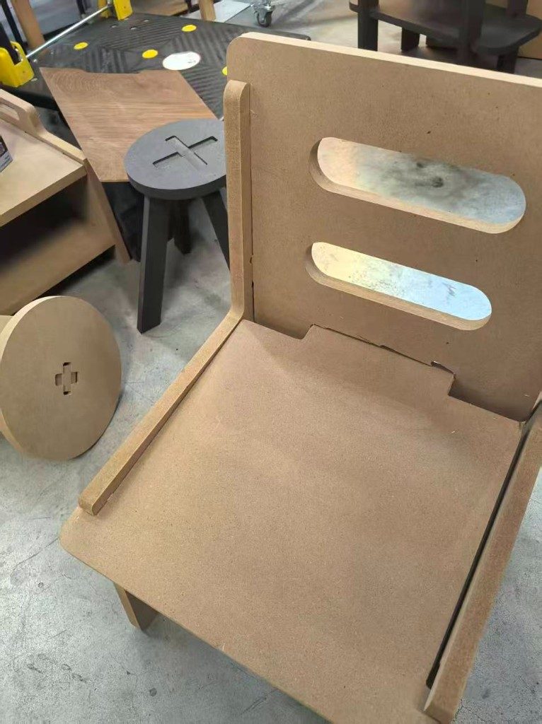
I measured our board at about 18.2 mm and built the slot width around that number instead of assuming “18 mm” from the label. The model breaks into five routed pieces: a backrest with horizontal grip slots, a seat panel, one cross brace, and two mirrored side frames with triangular cutouts. Tabs and slots are meant to press together without glue or screws.
Inner corners of the slots include small dogbone fillets so an end mill can reach the full slot width — without them, square tabs bind on the rounded corners the bit leaves behind. I exported the nested layout as DXF for Mastercam.
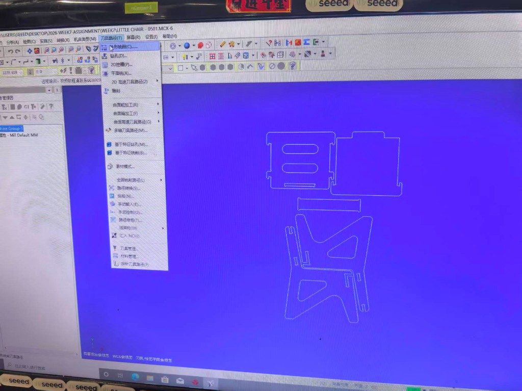
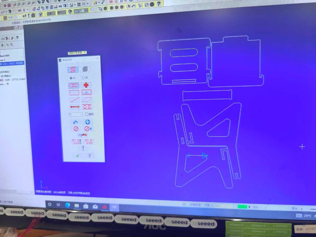
CAM: Mastercam toolpaths
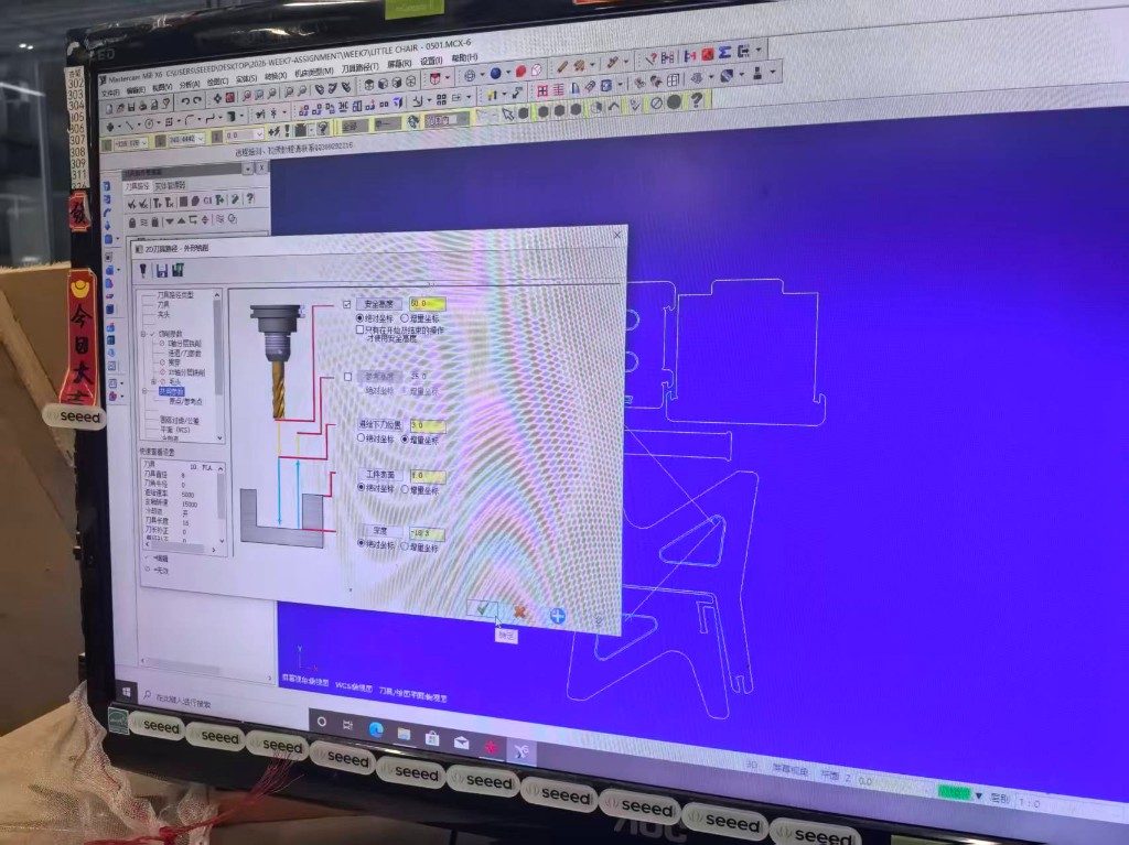
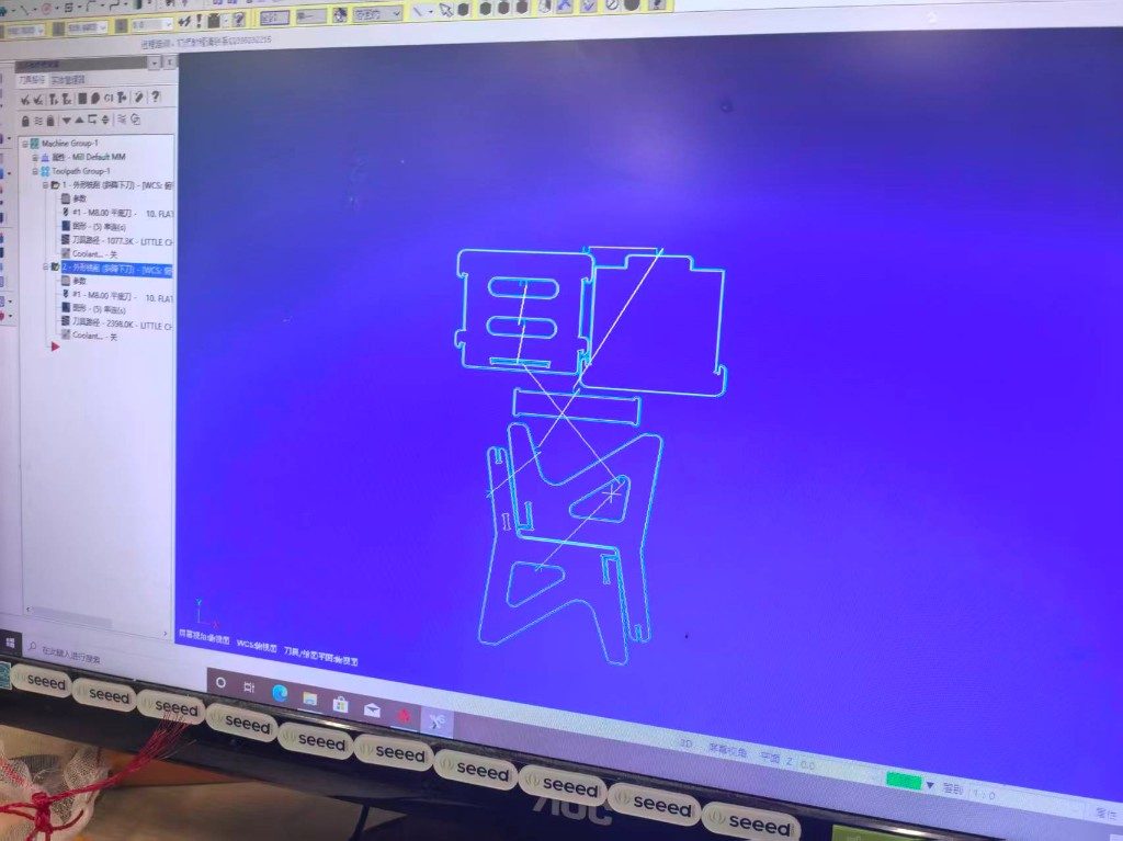
At Chaihuo we opened the DXF in Mastercam (LITTLE CHAIR - 0501.MCX-6) and
built two 2D contour groups: one for interior features and pockets, one
for outer profiles that free the parts from the sheet. I chained each closed loop before
posting.
Parameters I kept for the final posted file (also what appears in the G-code header):
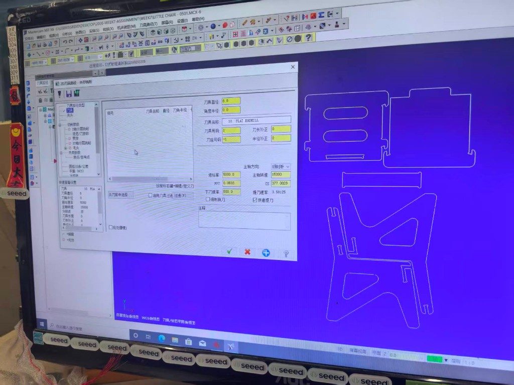
- Tool: 8 mm flat end mill (listed in the tool library as
10 FLAT ENDMILL; the name is misleading and the diameter field reads 8.0 mm) - Spindle: 10 000 rpm
- Feed: 5 000 mm/min cutting, 500 mm/min on plunge
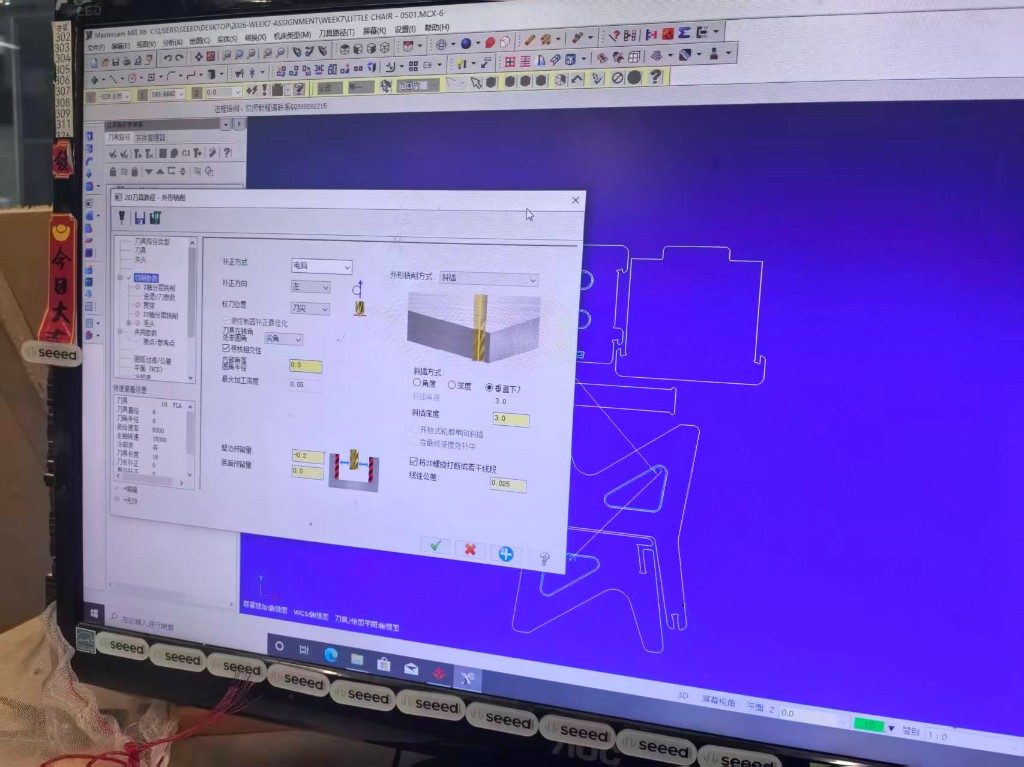
- Wall stock: −0.2 mm (slightly wider slots for press-fit)
- Depth: −18.3 mm in stepped passes (0.1 mm past measured thickness so the panel cuts through cleanly)
- Entry: ramp / step-down rather than a straight plunge on the full depth
Machining on the TC1325B
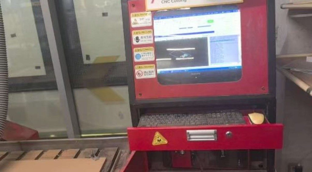
I followed the group checklist on the same machine: load the posted .NC file,
place and clamp the panel, install the 8 mm cutter, close the dust hood, touch off
work zero, then stay at the console for the full run. The controller preview showed the
nested chair outlines before the spindle started.
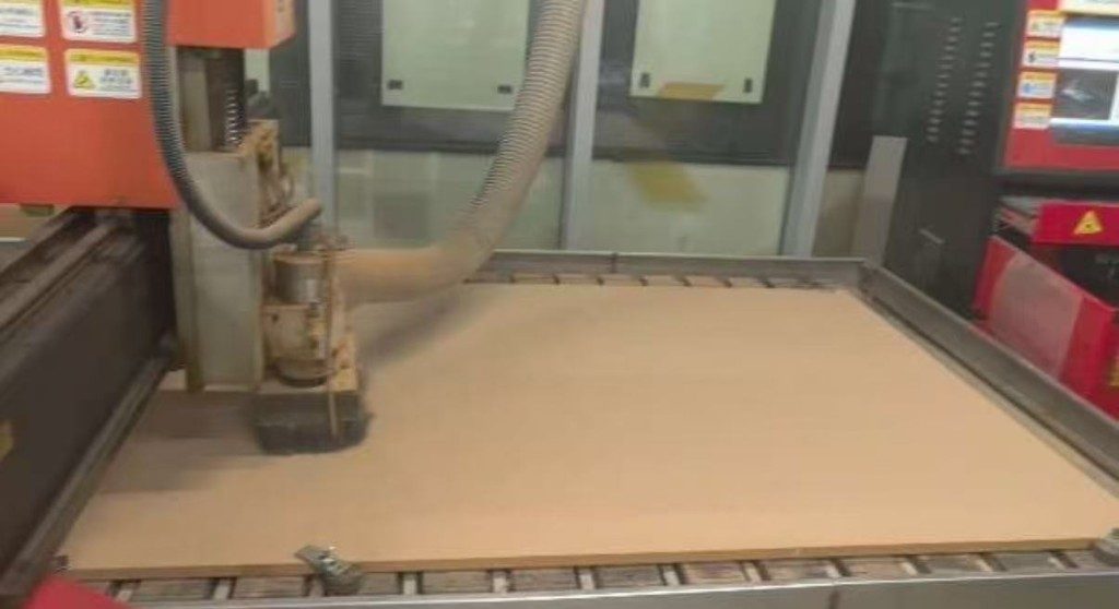
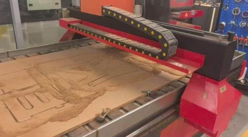
Interior cuts finished before the outer contours, which kept the sheet stable until the parts were ready to break out. After the job I vacuumed the MDF dust before lifting pieces.
Assembly
The −0.2 mm wall stock was enough that I could press the rails into the end frames by hand without filing, though a few joints needed more force than expected. The cross brace and seat lock the side frames square; the backrest slots onto the top tabs. No fasteners.
What went wrong and what I changed
- Measure thickness, don’t guess. Modeling at a nominal 18 mm would have been wrong for this board; 18.2 mm drove every slot width.
- Put clearance in CAM. The −0.2 mm wall stock did more for fit than tweaking slot width by eye in Fusion.
- Dogbones matter. Without the corner fillets, square tabs would bind on the rounded inside corners left by the bit.
- Tool library names lie. Mastercam called the cutter
10 FLAT ENDMILLwhile the diameter field read 8 mm. I learned to read the diameter column, not the label, before posting. - Material preset was wrong in the file header. The posted NC still says aluminum in a comment line; the actual stock was wood MDF. It did not change the feeds we ran, but I should have switched the material template before export.
- Cut order matters. Inside contours before outside profiles kept the panel from rattling loose mid-job.
Design files
Download 2D layout (DXF) Download posted G-code (NC)
Reflection
A CAD file I drew became furniture I could pick up off the floor, the first time that happened for me. The chair is intentionally small, but running it on a meter-class machine still covered nesting, joint clearance, and why the group safety sequence (clamp check, hood closed, hands out while the spindle spins) matters. In CAM, “looks fine on screen” still has to answer whether the bit fits in that inside corner; dogbones and −0.2 mm stock were what made the chair stand.