Week 15 — Interface and application programming
Group assignment for this week is on the Chaihuo Week 15 group assignment page. The rest of this page is my individual work.
Individual assignment
For this assignment I treated the interface as an on-board UI, not a desktop
dashboard. The UI runs in pcb_testing.ino on the milled XIAO carrier I designed in
Week 6 and made in Week 8. The 1602 I2C LCD
is the display, the KY-040 encoder from Week 9 is the user input, and
USB serial is the protocol layer I use from the host computer to test communication with the
board.
| Requirement | How I cover it |
|---|---|
| User Interface using programming | Four programmed LCD pages: W8 SYSTEM, W9 INPUT, W10 OUTPUT, and W11 COMMUNICATIONS. |
| User input | KY-040 encoder rotation and switch. Long press changes pages; rotation changes values on the output page. |
| Communication protocol | USB Serial at 115200 baud with DATA, READ, VAL n, and acknowledgement lines. |
| Board I designed and made | The same milled XIAO carrier documented in Week 6 and Week 8. |
Firmware: four LCD pages
pcb_testing.ino cycles through four screens when you hold the encoder switch
for two seconds: W8 SYSTEM, W9 INPUT, W10 OUTPUT, and W11 COMMUNICATIONS. Rotation updates
encoder fields on W9; on W10 it changes val on the LCD. W11 shows
val plus serial rx/tx counters (R and T on the display).
The fourth page title reads W11 COMMUNICATIONS because I wrote that screen into the firmware with Week 11 in mind (serial traffic and rx/tx counts on the LCD). Week 15 is where I actually use it as the interface-programming page: the serial demo below stays on W11 so the host traffic and LCD feedback can be seen together. The other three pages are not placeholders. Their full subsystem demos are documented in their own weeks: W8 SYSTEM in Week 8, W9 INPUT in Week 9, and W10 OUTPUT in Week 10.
How the screen UI is controlled
The LCD interface has two control paths. The encoder is the local user control on the board. USB serial is the host-side protocol path I used for testing and for setting values without touching the encoder.
| Control path | What the user does | What changes on the UI |
|---|---|---|
| Encoder long press | Hold the KY-040 switch for about two seconds. | The LCD moves to the next page: W8, W9, W10, then W11. |
| Encoder rotation | Turn the knob while the output page is active. | The Val field changes on the LCD. |
| Encoder switch readout | Press or release the shaft switch on the input page. | W9 shows the switch and quadrature state from the input device. |
| USB serial command | Send VAL n or READ from the host computer. |
W11 shows value and rx/tx counters while the monitor shows the reply line. |
Hardware
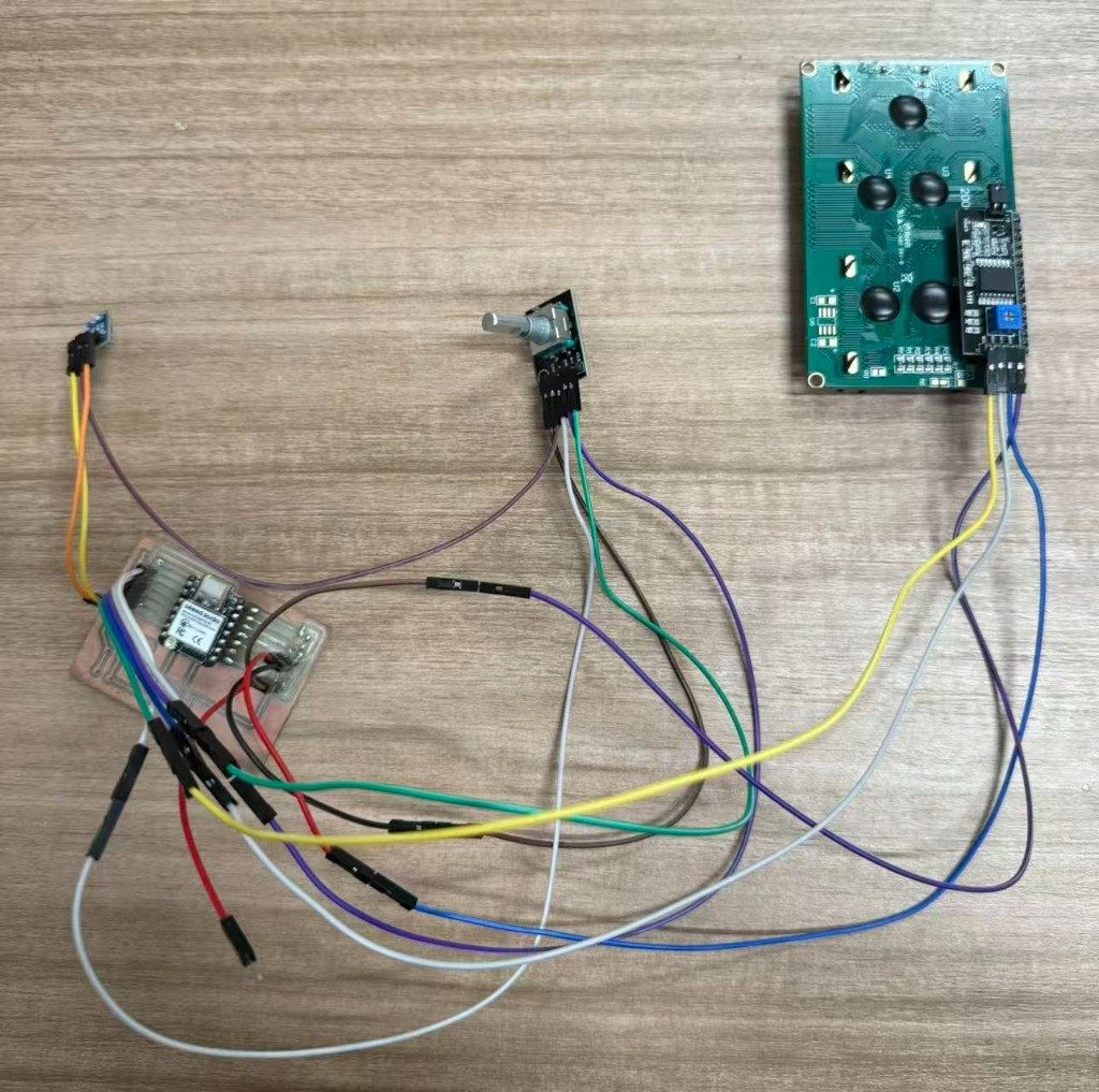
| Device | Connection |
|---|---|
| KY-040 SW / DT / CLK | D1 / D2 / D3 |
| LCD I2C backpack | D4 SDA, D5 SCL (100 kHz) |
| USB serial to host | 115200 baud, newline-terminated ASCII lines |
Serial protocol
The host and board share one protocol. While the sketch runs, the firmware prints a
DATA,... line about every 500 ms — the serial window keeps updating on its
own. Commands from the host get a direct reply and bump the counters shown on W11.
| Direction | Line | Meaning |
|---|---|---|
| Host → board | READ |
One status snapshot (READ,page=...,val=...,steps=...,rx=...,tx=...). |
| Host → board | VAL n |
Set output value 0–999; LCD row updates immediately. |
| Board → host | DATA,... |
Periodic telemetry (same fields as READ). |
| Board → host | OK,VAL=n / ERR,... |
Command acknowledgement. |
| Board → host | EVENT,page=... |
Page changed after a 2 s button hold. |
Command handling in firmware:
void handleCommand(String command) {
  command.trim();
  command.toUpperCase();
  serialRxCount++;

  if (command == "READ") {
    printStatusFrame();
  } else if (command.startsWith("VAL ")) {
    int value = command.substring(4).toInt();
    if (value < 0) value = 0;
    if (value > 999) value = 999;
    val = value;
    sendResponse(String(F("OK,VAL=")) + val);
  } else {
    sendResponse(F("ERR,USE VAL n OR READ"));
  }
}
Host protocol test on W11
The Arduino IDE Serial Monitor is not the UI I am claiming for this week. I use it as a
host-side protocol test window while the real UI stays on the LCD. Once
pcb_testing.ino is running, the board streams DATA,... lines about
every 500 ms whether or not I type anything. I can also send VAL n or
READ; those commands get a direct reply and bump the R/T counters on the W11
LCD page.
DATA,...— automatic telemetry on a fixed interval; this is what fills the monitor scrollback during normal operation.VAL n— setsval(0–999), repliesOK,VAL=n, and updates the Val field on W11 (and W10 when that page is active).READ— requests one immediate status snapshot in the same field layout asDATA; useful when I want a single line on demand instead of waiting for the next periodic frame.
DATA,... lines scroll in the monitor, and serial
commands can update the value shown on the LCD.
How to reproduce (not the video script)
The video above was recorded after upload; it documents behaviour, not the flash sequence. To run the same setup yourself:
- Flash
pcb_testing.ino(Seeed XIAO ESP32-S3 board package). - Open Serial Monitor at 115200 baud, newline ending — you should see
DATA,...lines appearing continuously. - Hold the encoder button until the LCD title reads W11 COMMUNICATIONS.
- Optionally send
VAL norREADand compare the monitor line with Val and R/T on the display.
Architecture
| Component | Role |
|---|---|
pcb_testing.ino |
On-board UI: encoder input, LCD pages, page state, handleCommand(),
periodic DATA frames, and W11 rx/tx counters. |
| Arduino IDE Serial Monitor | Host test tool for the serial protocol: continuous DATA stream plus
optional VAL / READ commands. |
Problems and fixes
| Issue | Fix |
|---|---|
No DATA, lines in Monitor |
Check 115200 baud and the correct USB serial port for the XIAO. |
VAL accepted but LCD unchanged |
Switch to W10 OUTPUT or W11; other pages do not show Val on row 1 the same way. |
| Commands seem ignored | Send a newline after each line; set Monitor line ending to Newline. |
Takeaway from the group tool comparison
My Week 15 UI is deliberately small: LCD pages on the board, encoder input, and ASCII serial lines for host testing. The group exercise still mattered because it made me name which tool owns each layer: flash, edit, simulate, or glue services, instead of treating programming as one generic step.