Input Devices
Grpup Assignment
Analog Signal Measurement Using an LDR Sensor with ESP32
In embedded systems, it is essential to understand how microcontrollers can read signals from both analog and digital sensors. Analog sensors allow the measurement of physical variables such as light, temperature, or humidity through voltage variations, which are then interpreted by the microcontroller’s analog-to-digital converter (ADC).
In this experiment, an LDR (Light Dependent Resistor) was used. This is a light-sensitive resistor whose resistance varies depending on light intensity. This variation makes it possible to obtain a proportional voltage using a voltage divider, which can be read by the ESP32 through an analog input.
Materials
For this experiment, the following materials were used:
- ESP32 development board
- LDR sensor
- 10 kΩ resistor
- Breadboard
- Jumper wires
- USB cable
- Computer with Arduino IDE
- Light source (mobile phone flashlight)
Development of the Experiment
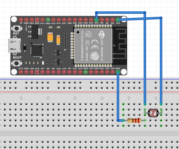
First, the circuit was assembled using a voltage divider composed of the LDR and a 10 kΩ resistor. This configuration made it possible to obtain an analog signal proportional to the light intensity.
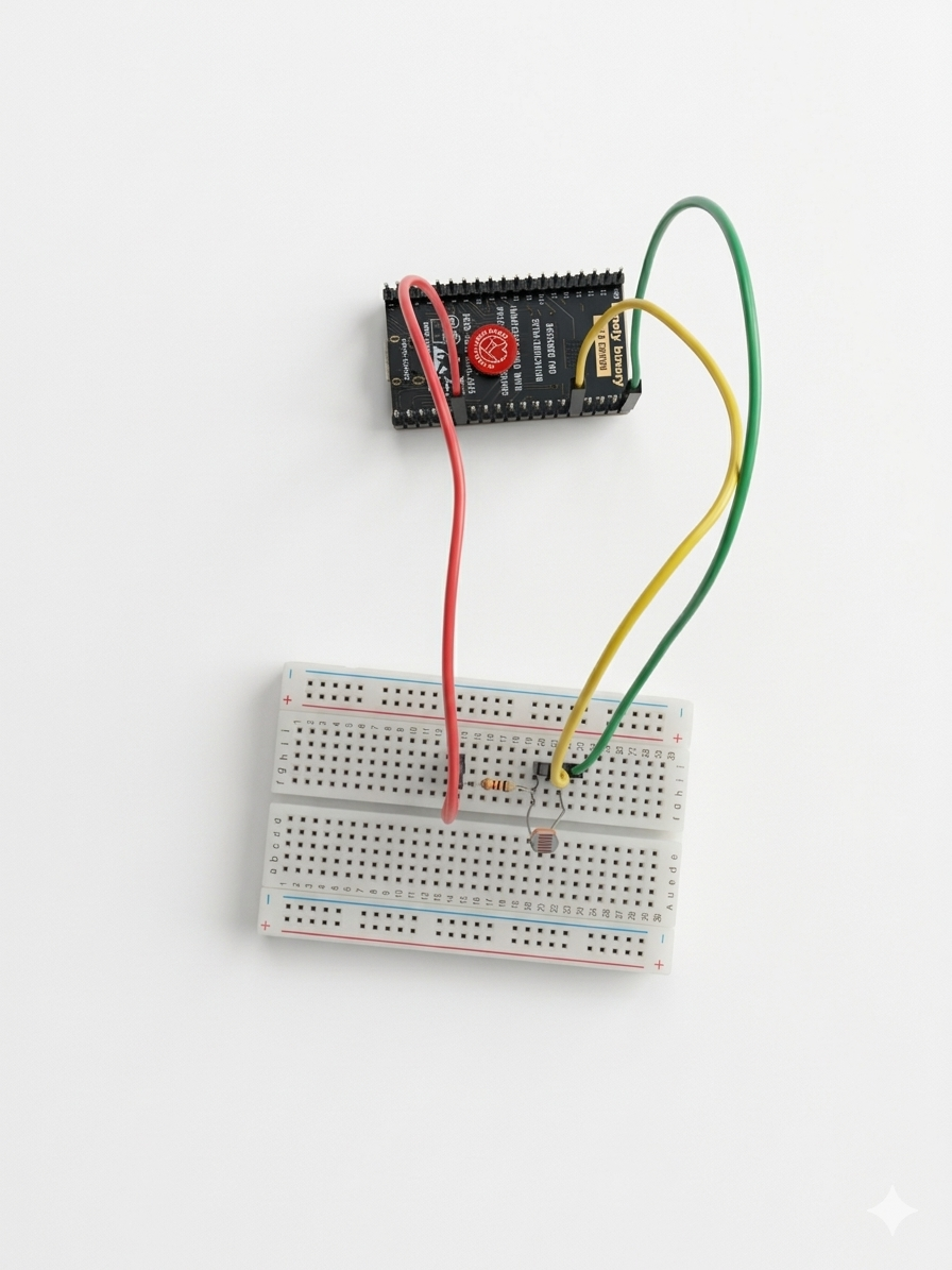
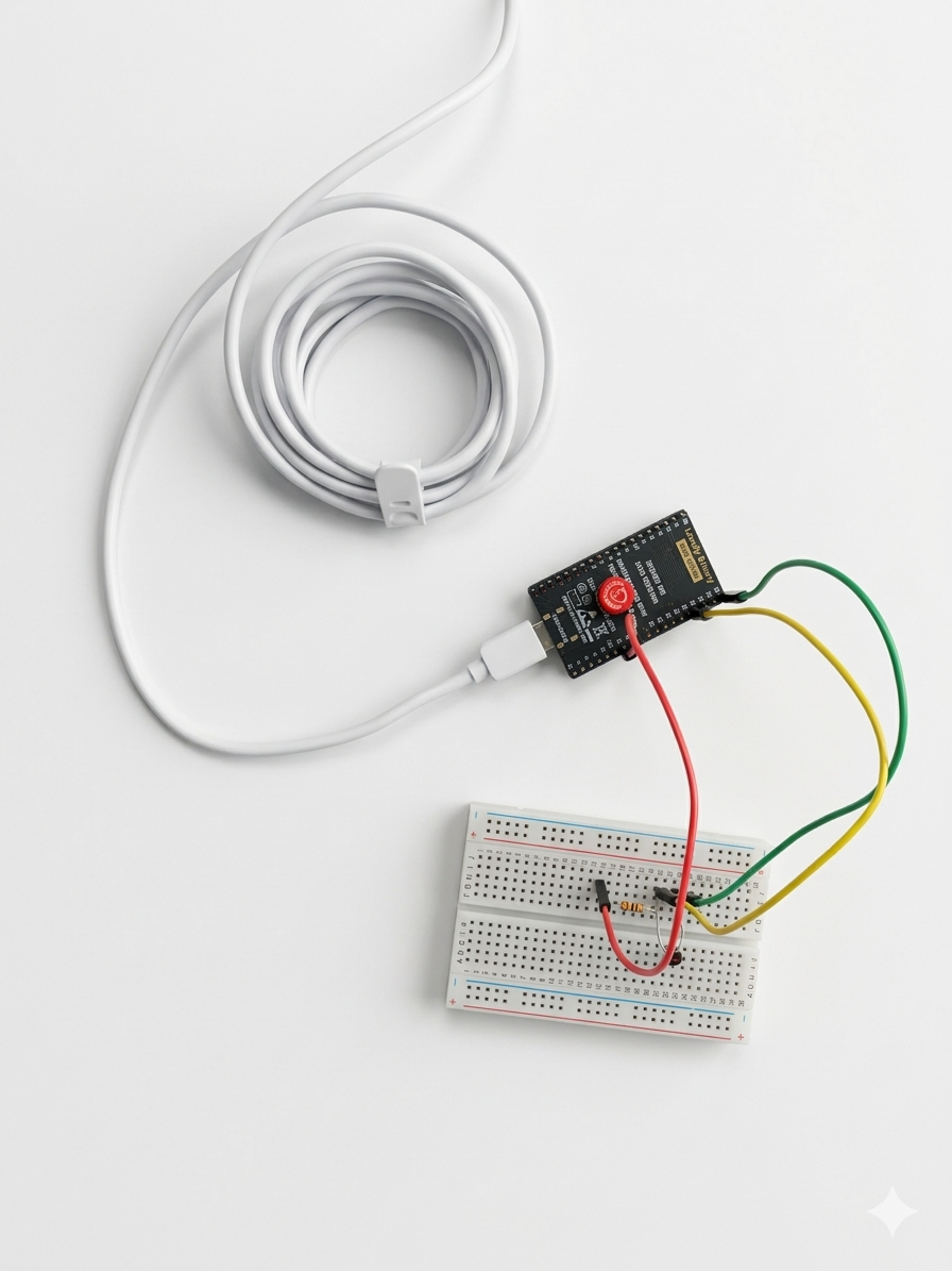
Subsequently, the circuit was connected, where the junction point between the LDR and the resistor was connected to the ESP32 GPIO34 pin, which allows analog readings. Then, the program was uploaded to the microcontroller using the Arduino IDE software, in order to read the voltage values generated by the sensor and display them on the serial monitor.
Once the program was uploaded, the values were observed on the serial monitor while varying the amount of light received by the LDR, either by covering it with a hand or illuminating it with a flashlight.
It was observed that the values varied according to the light intensity (sensor covered, ambient light, and direct light on the LDR), demonstrating the proper operation of the sensor.
Connection Diagram
The circuit was connected as follows:
- One terminal of the LDR connected to 3.3V
- The other terminal connected to GPIO34
- From that same node, a 10 kΩ resistor connected to the ESP32 GND
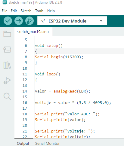
Implemented Code
The following code was used to read the analog sensor and display the values on the serial monitor:
#include <Arduino.h>

#define LDR 34
int valor = 0;
float voltaje = 0;

void setup()
{
    Serial.begin(115200);
}
void loop()
{
    valor = analogRead(LDR);
    voltaje = valor * (3.3 / 4095.0);
    Serial.print("ADC Value: ");
    Serial.println(valor);
    Serial.print("Voltage: ");
    Serial.println(voltaje);
    delay(1000);
}
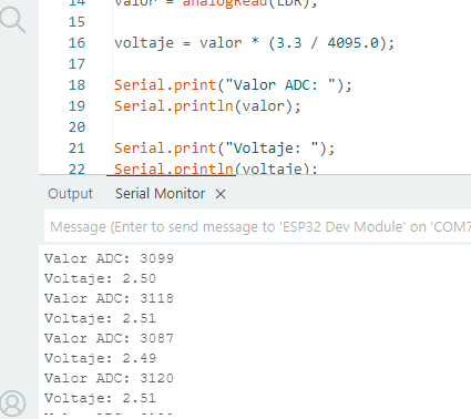
Values Obtained When Operating the LDR
During the experiment, approximate values such as the following were obtained:
| Condition | ADC Value | Voltage |
|---|---|---|
| LDR covered (darkness) | 128 | 0.10 V |
| Ambient light | 2128 | 1.71 V |
| Direct light | 3882 | 3.13 V |
These values demonstrate how the voltage increases as the LDR receives a greater amount of light.
Conclusions
It is concluded that the ESP32 allows accurate reading of analog signals through its ADC, facilitating the acquisition of data from sensors. The LDR proved to be a simple yet effective sensor for measuring light variations through changes in voltage.
Digital signal measurement using a pushbutton with arduino
In electronic and embedded systems, it is important to understand the behavior of digital signals, which operate with two logical states: HIGH and LOW. These signals are used by devices such as switches, pushbuttons, and digital sensors to indicate state changes.
In this experiment, a pushbutton was used as a digital input device to observe how Arduino can detect state changes through voltage readings. Although the pushbutton is a digital device, an analog input was used in order to measure the voltage generated when the button changes state.
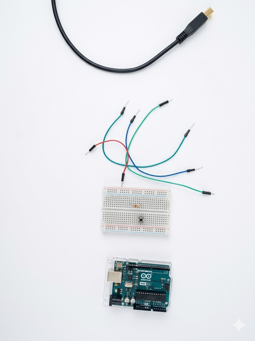
Materials
- Arduino UNO
- Push button
- 10 kΩ resistor
- Breadboard
- Jumper wires
- Arduino IDE software
- USB cable
Development
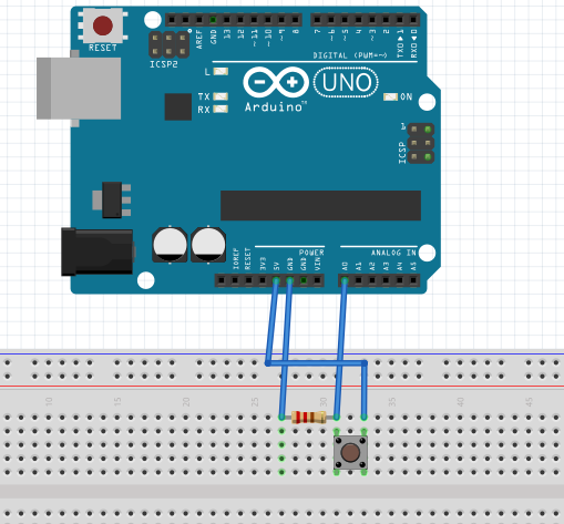
- First, the pushbutton was placed on the breadboard to facilitate circuit assembly. Then, one terminal of the pushbutton was connected to the Arduino 5V pin and the other terminal to the analog pin A0.
- Next, a 10 kΩ resistor was connected between pin A0 and GND to ensure the pin has a defined state when the button is not pressed, preventing incorrect readings.
- After that, the Arduino was programmed using the Arduino IDE software to read the analog values from pin A0 and convert them into voltage values.
- Finally, tests were carried out by pressing and releasing the pushbutton to observe how the values changed in the serial monitor.
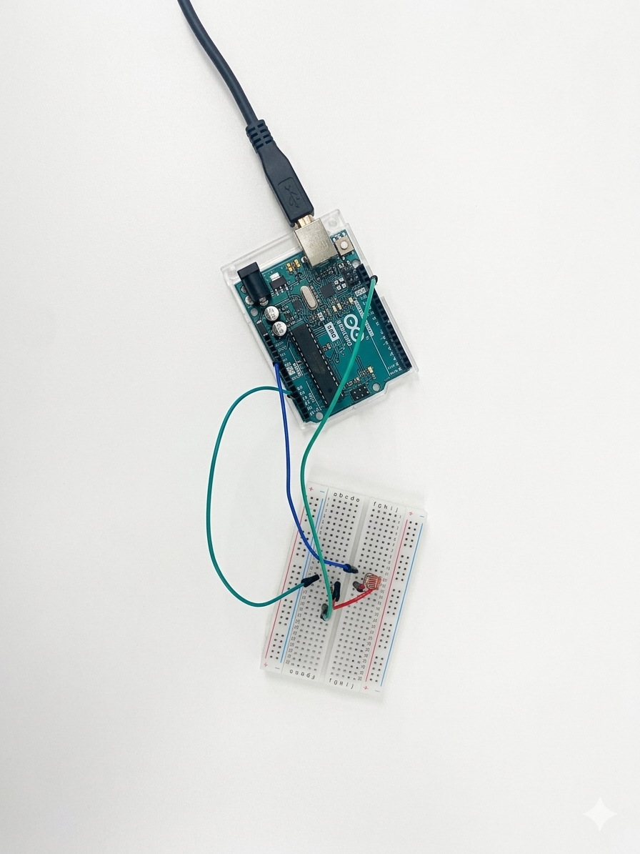
Connection Diagram
Connect as follows:
- One terminal of the pushbutton to 5V
- The other terminal to the A0 pin
- From A0, connect a 10 kΩ resistor to GND
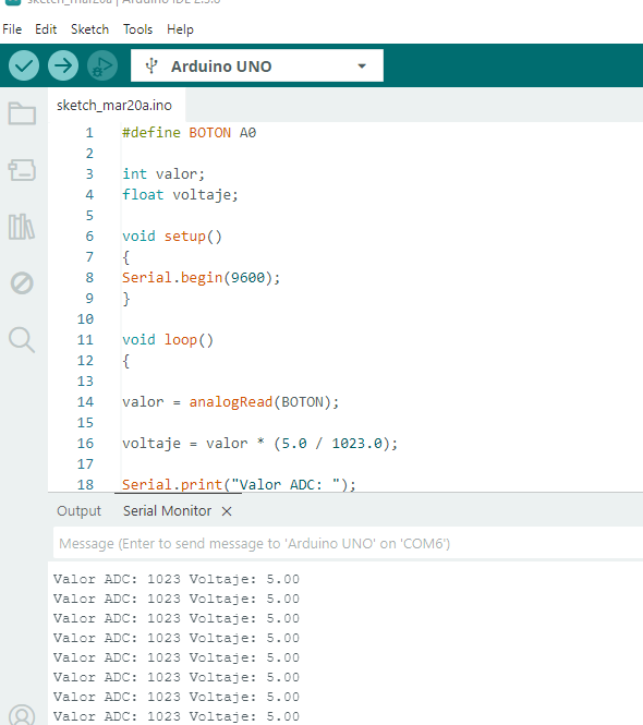
Implemented Code
#include <Arduino.h>
#define BOTON A0
int valor;
float voltaje;
void setup()
{
    Serial.begin(9600);
}
void loop()
{
    valor = analogRead(BOTON);
    voltaje = valor * (5.0 / 1023.0);
    Serial.print("ADC Value: ");
    Serial.print(valor);
    Serial.print(" Voltage: ");
    Serial.println(voltaje);
    delay(500);
}
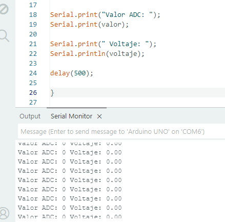
Result
When the pushbutton is not pressed, the analog pin A0 remains connected to ground (GND) through the pull-down resistor, so the Arduino registers a voltage close to 0V, which corresponds to an approximate digital value of 0 in the ADC reading.
| Value | Result |
|---|---|
| ADC | 0 |
| Voltage | 0 V |
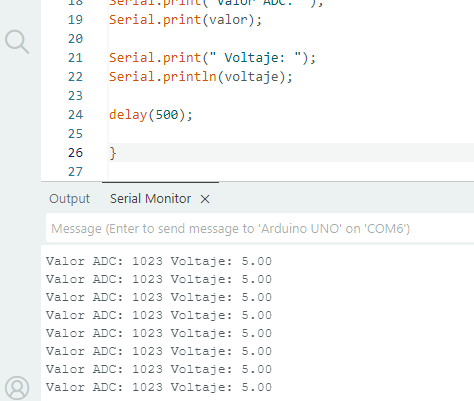
On the other hand, when the pushbutton is pressed, the A0 pin receives 5V from the Arduino, causing the analog reading to reach values close to 1023, which corresponds to the maximum measured voltage. This behavior makes it possible to clearly identify the states of the pushbutton through voltage variation and its conversion into digital values.
| Value | Result |
|---|---|
| ADC | 1023 |
| Voltage | 5 V |
Conclusions
Arduino can correctly detect the state changes of a pushbutton through voltage measurement. Additionally, it was verified that by using the ADC, it is possible to convert electrical signals into digital values for analysis.