Wildcard week: development of a line follower system for a robotic platform based on ESP32.
Introduction
As part of the Wildcard Week assignment, a line-following system was designed and adapted to a robotic platform using an ESP32 microcontroller and a set of line-following sensors. The purpose of this activity was to explore and implement technologies related to the autonomous control of robots, in this case, using a line-following system for navigation around the university campus. For this experiment, a robotic platform was used to which the line-following subsystem was adapted to understand the behavior of the sensors, evaluate motion control strategies, and gain practical experience in the integration of electronic hardware and software. During the development process, several experimental tests were conducted to analyze the system's performance and validate the operating principles between motor control and line detection. The results obtained provided valuable information for future implementations and helped strengthen the skills and knowledge necessary to integrate these technologies into the final project.
Materials
The following materials were used to build the prototype:
- ESP32 Development Board
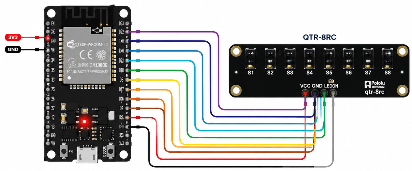
- QTR-8RC Line Sensor Array
- Robotic Platform
- Jumper Wires
- Power Supply
- Computer for Programming and Serial Monitoring
Development
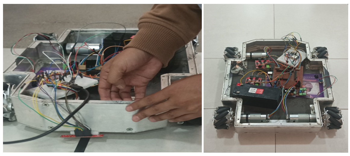
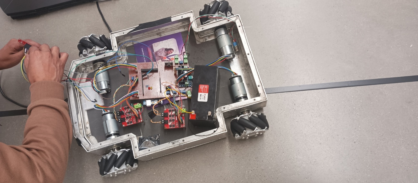
- The project began with the integration of the ESP32 and the QTR-8RC line sensor array into the robot chassis. The ESP32 was configured as the primary controller responsible for processing sensor inputs and generating the control signals required to drive the robot.
- The line follower sensing and main control are performed on the ESP32 board, which is connected via serial port to an Arduino MEGA, which performs low-level control for the motors.
- The sensor array was connected directly to the ESP32, allowing the microcontroller to acquire data from the track surface and determine the robot's position relative to the line. Once the electronic assembly was completed, the code development phase was initiated.
Code Development
The code was developed using the Arduino IDE and uploaded to the ESP32 development board. The program was designed to establish serial communication, process incoming commands, and monitor system behavior during testing. Through the serial interface, the robot could receive control instructions and provide debugging information, facilitating the evaluation of sensor responses and overall system performance.
The following code was used during the implementation and testing phase of the project:
// =====================================================
// ESP32 - Robot Control and Serial Communication
// =====================================================

#define RXD2 16
#define TXD2 17

String inputString = "";

// Test wheel speeds
float w1 = 0.0;
float w2 = 0.0;
float w3 = 0.0;
float w4 = 0.0;

void setup() {
  Serial.begin(115200);
  Serial2.begin(19200, SERIAL_8N1, RXD2, TXD2);

  delay(1000);

  Serial.println("==================================");
  Serial.println("ESP32 Ready");
  Serial.println("Available Commands:");
  Serial.println("");
  Serial.println("1) Send wheel velocities:");
  Serial.println("I5B5C5D5F");
  Serial.println("");
  Serial.println("2) Send PID values:");
  Serial.println("P1A1.0B0.0C0.0F");
  Serial.println("P2A1.0B0.0C0.0F");
  Serial.println("P3A1.0B0.0C0.0F");
  Serial.println("P4A1.0B0.0C0.0F");
  Serial.println("");
  Serial.println("3) Request measured velocities:");
  Serial.println("G");
  Serial.println("==================================");
}

void loop() {

  while (Serial.available()) {
    char c = Serial.read();

    if (c == '\n' || c == '\r') {
      if (inputString.length() > 0) {
        sendCommand(inputString);
        inputString = "";
      }
    } else {
      inputString += c;
    }
  }

  while (Serial2.available()) {
    char c = Serial2.read();
    Serial.write(c);
  }
}

void sendCommand(String command) {
  Serial2.print(command);

  Serial.print("Sent: ");
  Serial.println(command);
}
- The code was successfully uploaded to the ESP32 and used during the experimental phase to monitor communication and evaluate the overall behavior of the system.
- After completing the assembly process, a series of tests were carried out on a track containing a reference line.The intended behavior was for the robot to detect the line and continuously adjust its trajectory to remain centered on the path. However, during testing, the robot consistently moved forward without performing the necessary steering corrections. Although the sensor was able to detect surface variations, the control system was unable to maintain effective line tracking.
- Following multiple test iterations and adjustments, several possible causes were identified. These included variations in ambient lighting conditions, electrical noise affecting sensor readings, insufficient sensor calibration, and sensitivity-related issues.Due to the limitations encountered, the results were documented and analyzed to support future development and optimization efforts.
Results
The project resulted in an experimental platform integrating the ESP32, the QTR-8RC sensor array, motor controllers, and the robotic chassis. However, the system failed to achieve full functionality due to limitations in data acquisition; the color and reflectivity of the ground prevented the sensors from accurately detecting the change in contrast between the line and the surface. Despite this, the testing process provided valuable insights into the sensor's sensitivity in different environments and the challenges of hardware integration.
Conclusion
The development of the experimental ESP32-based robot successfully demonstrated the integration of electronics, Embedded Programming, imputs and outputs fulfilling the primary objective of providing hands-on experience in PWM motor control and systems integration. After evaluating the prototype's performance, it was determined that the QTR-8RC sensor array would not be used in the final implementation due to contrast limitations detected in the test environment. Instead, the system will evolve toward a machine vision-based solution. The knowledge gained in this phase will serve as the foundation for the final project's navigation, although the mechanical structure and design of this prototype will be completely redesigned to accommodate the new image capture and processing system.
Download files← Main Page