What I did in Week 15
This week I will use an ESP32 to power an electronic device via a mobile application that connects via Bluetooth. The electronic device I will use is a speaker.
- Grupal: compare as many tool options as possible
- Individual: write an application that interfaces a user with an input &/or output device that you made
Group page
Group page linkProcess
Phase 1 ·
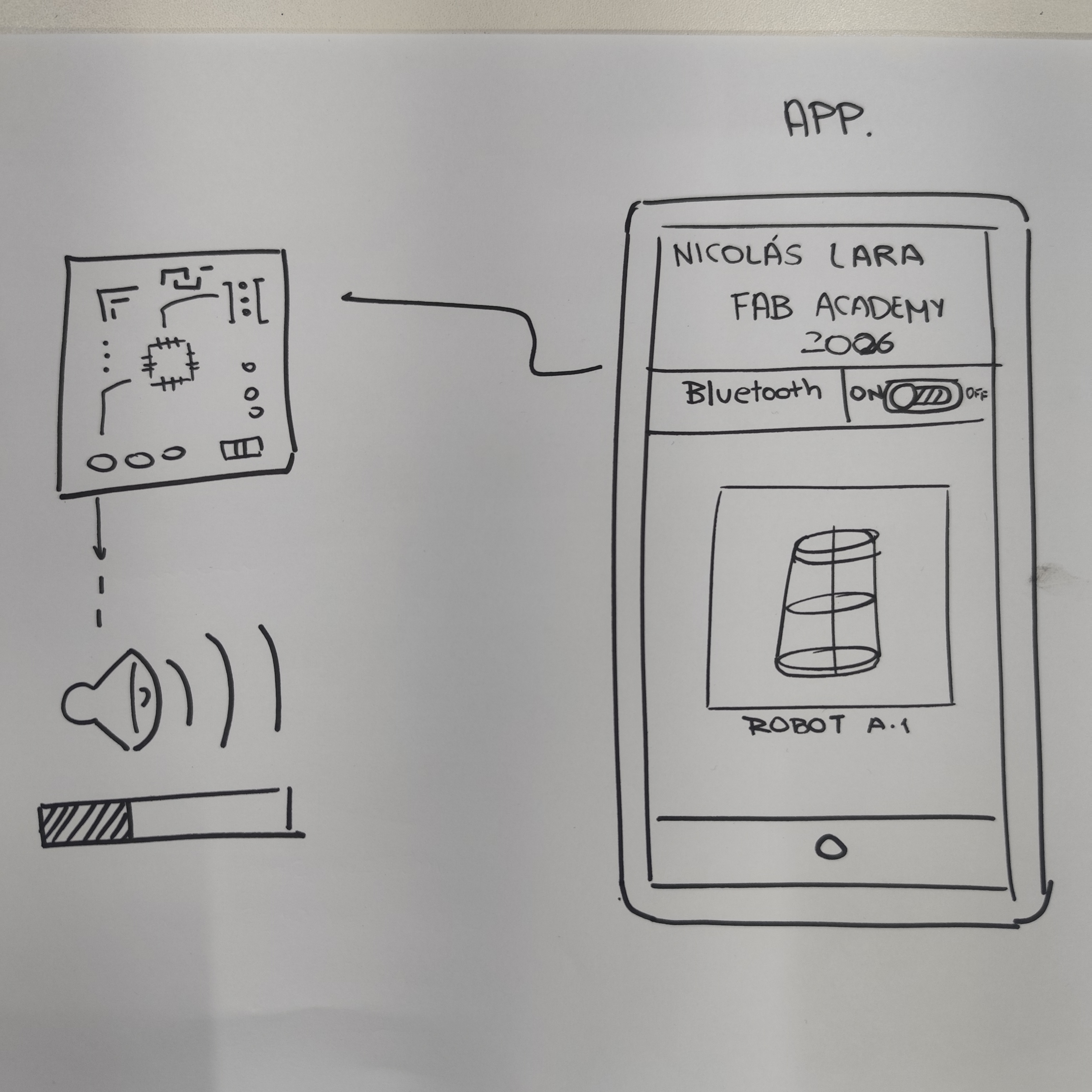
For my assignment this week, I will first establish what I want my application to have. The goal is to turn on a speaker from a button on my mobile phone's application via Bluetooth.
Phase 2 ·
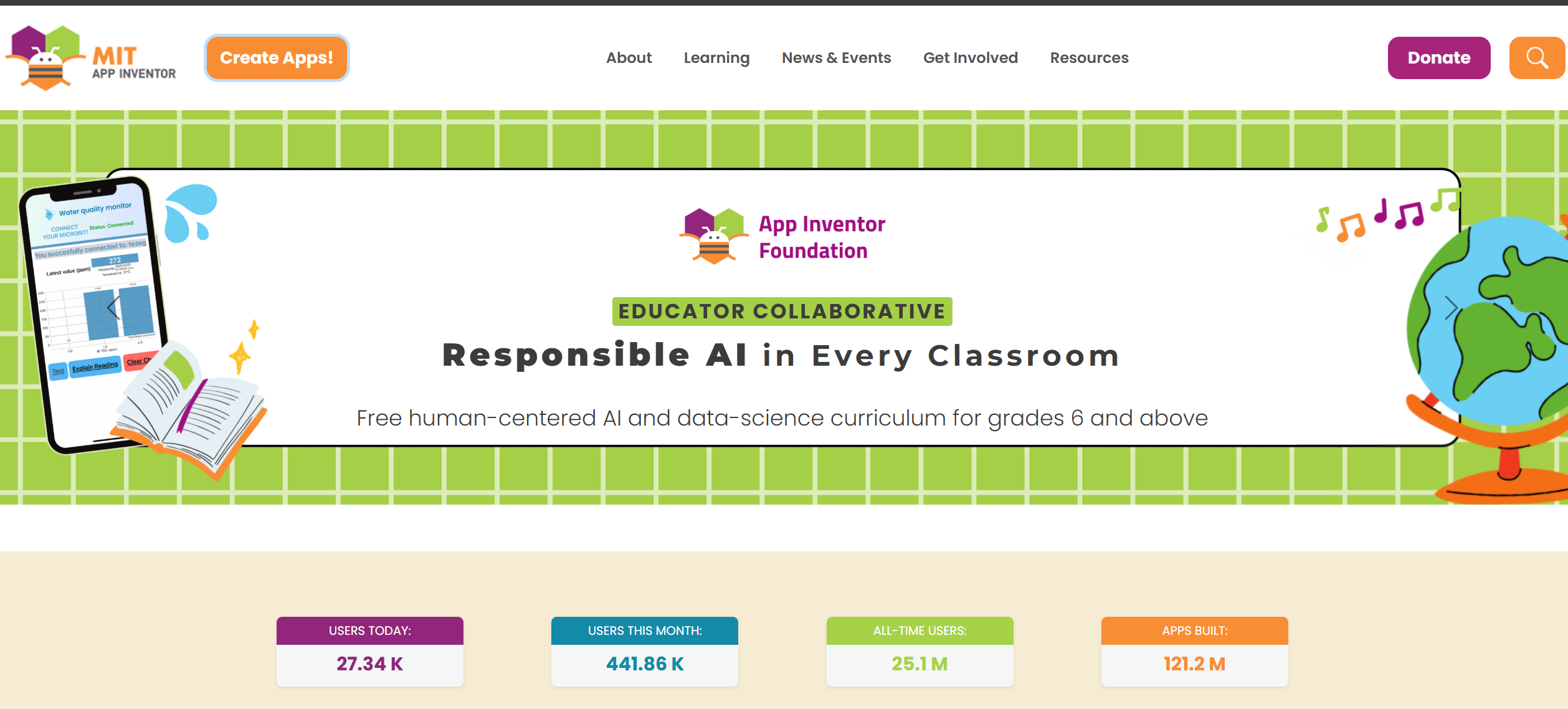
To achieve my goal I will use APP Inventor, which is a website that allows me to design and program mobile applications for different screen sizes.
Phase 3 ·
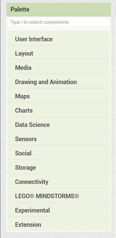
This online software allows me to add various things to my application such as buttons, images, text, and graphics.
Phase 4 ·
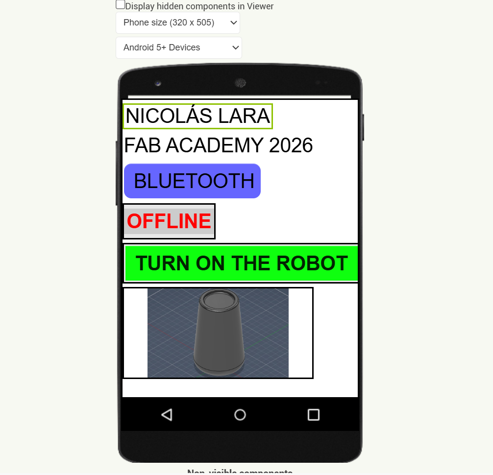
Creating my mobile application is very simple; I simply drag the spaces, buttons, or text where I want to place them, and I can change colors, text type, and other things depending on how I want my application to look.
Phase 5 ·
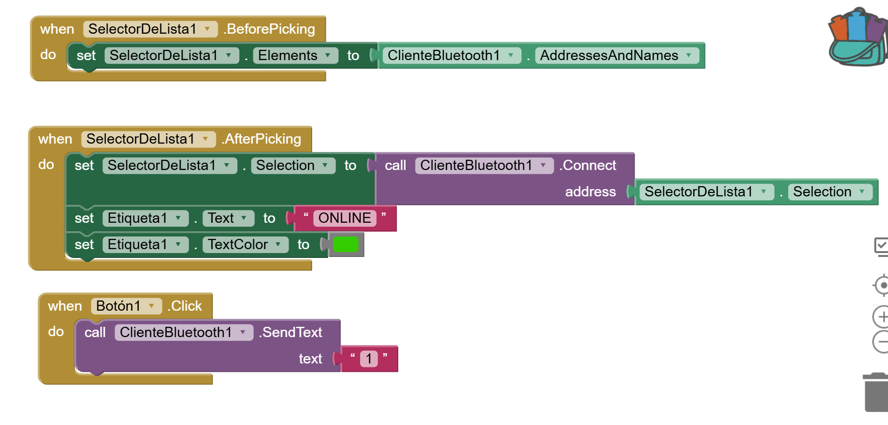
For the mobile app programming portion, App Inventor uses block-based programming where we select the available buttons and the actions we want them to perform. In this case, I have blocks to connect to Bluetooth and to turn on the lights.
Phase 6 ·
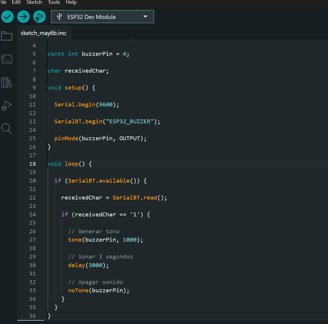
Once the mobile application interface is finished, the code for the esp32 is created, which will use Bluetooth, where we program the speaker to sound for 3 seconds when it receives the signal from the cell phone.
Phase 7 ·
Once the mobile application interface is finished, the code for the esp32 is created, which will use Bluetooth, where we program the speaker to sound for 3 seconds when it receives the signal from the cell phone.
Process 2
I've made another interface, but this time I used a more compact version of the board I made during the electronics production week. You can see the complete process for making the microcontroller with an Attiny412 by checking that week's documentation.
Phase 1 ·
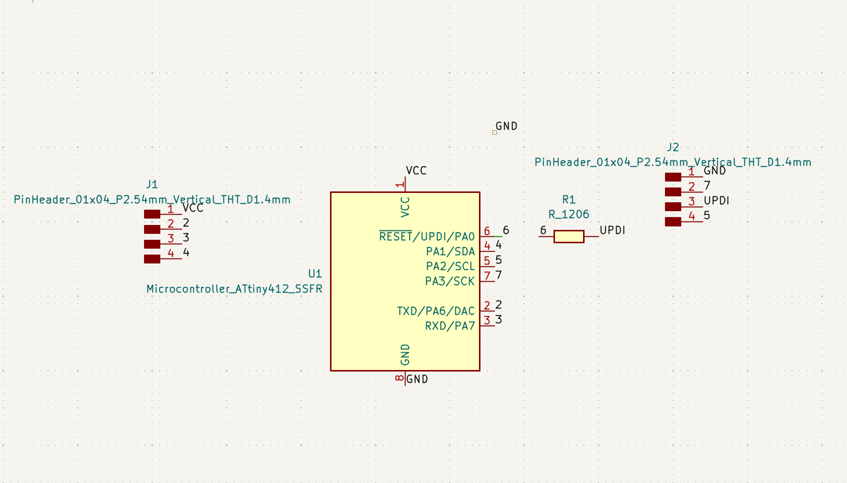
As I said before, I will use an attiny412 to control a small motor and a light that simulate the outputs of my final project, so my board will be as compact as I can make it.
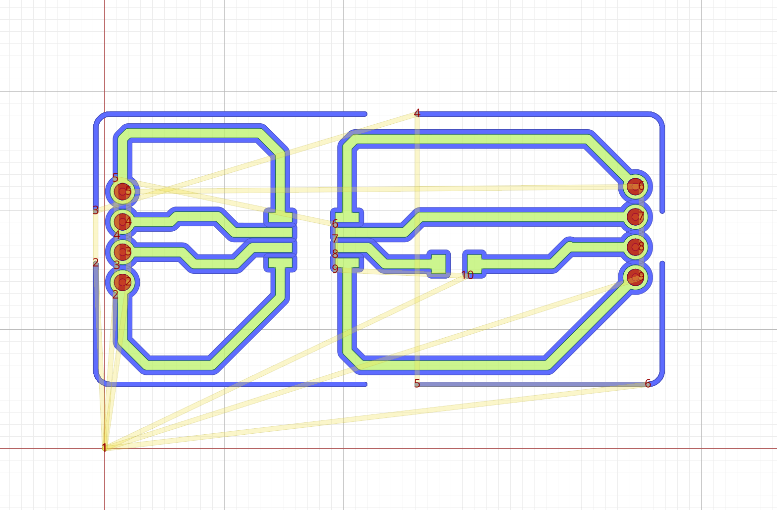
Phase 2 ·
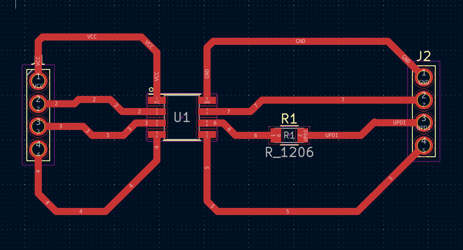
The PCB design of my board is made in such a way that I can solder the electronic components more easily; this time I made thicker electrical traces.
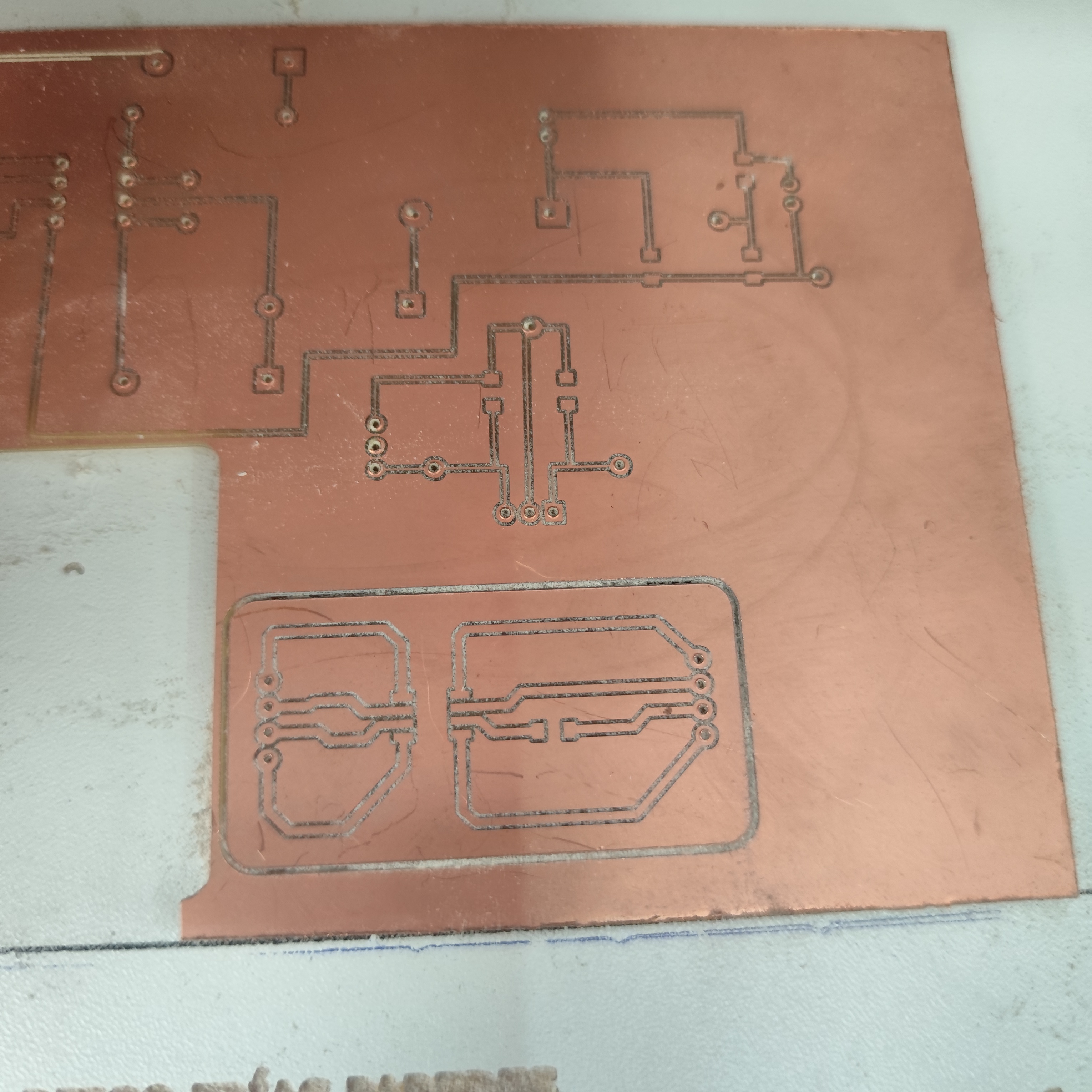
Phase 3 ·
In generating the g-code for manufacturing the board, I only used a 0.4 mm milling cutter because the holes made with the other milling cutters were too large for soldering the electronic components.
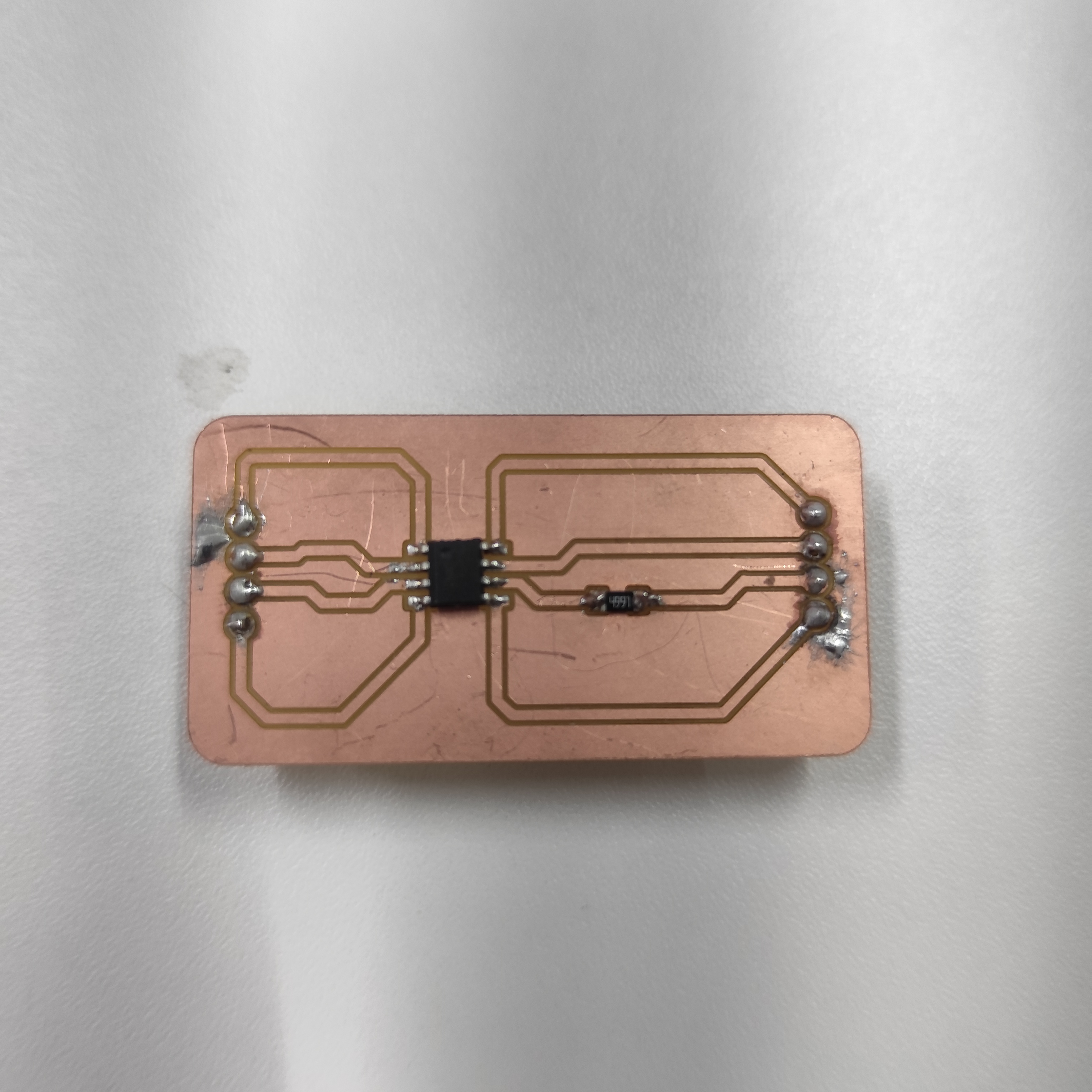
Phase 4 ·
Here we can see the result of my board with the ATtiny412
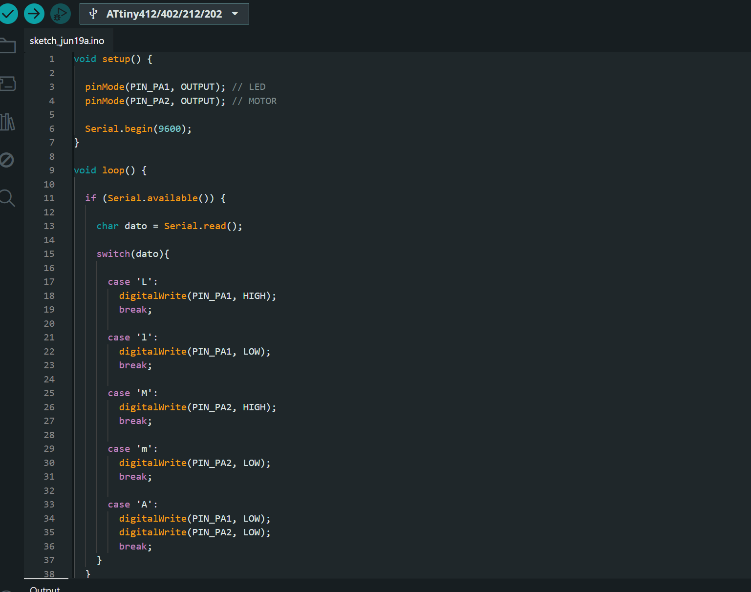
Phase 5 ·
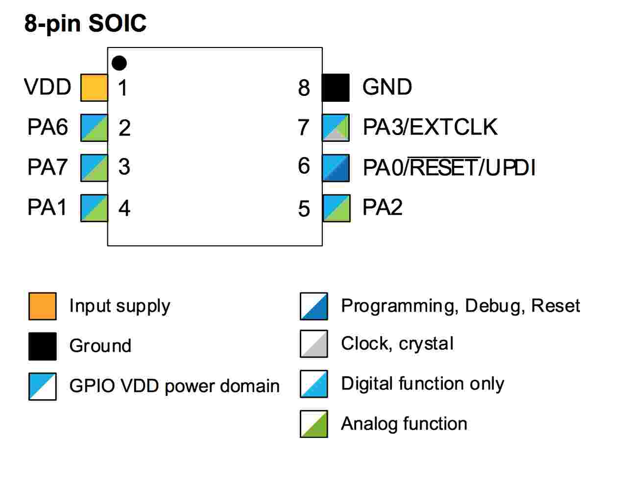
The code to upload to my board is that it receives instructions via serial port which turn on a light, a motor, and turn off the system; for this I will use ports PA1 and PA2 of the Attiny412.
Phase 6 ·
After uploading the code to the board, the connections should only be GND and PA6 (TX) to the Arduino's RX pin, and PA7 (RX) to the Arduino's TX pin. This ensures serial communication. It's also important to create a jumper on the Arduino between GND and RST to prevent its chip from functioning.
Phase 7 ·
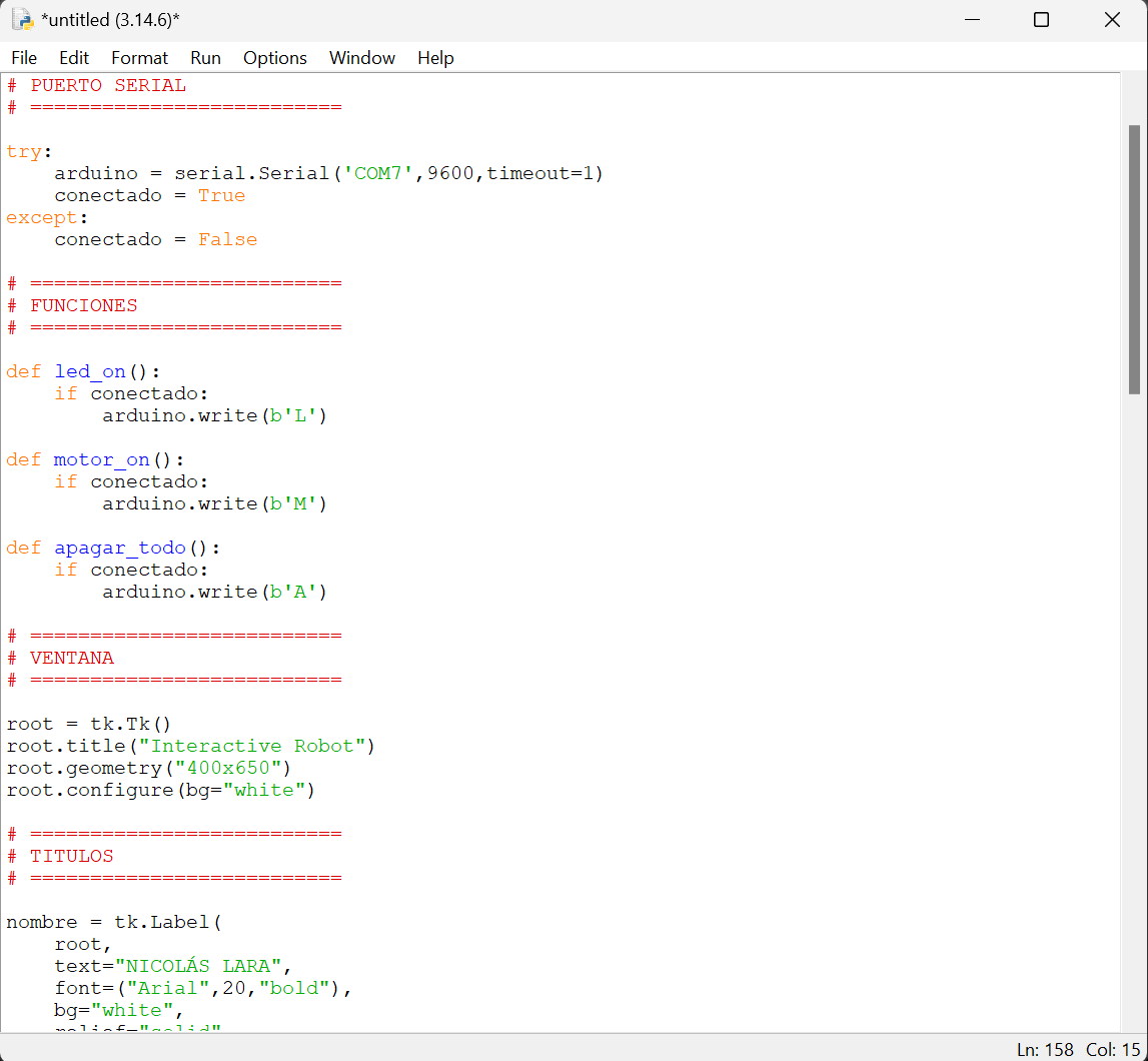
I created the graphical interface using Python. It's a bit more complicated than App Inventor, but you can make much more complex projects with it. In the code, I added serial communication, buttons with various colors, and boxes. These signals will be sent to my board via the Arduino Nano. I'm using the Arduino Nano as a USB-to-TLL converter.
Phase 8 ·
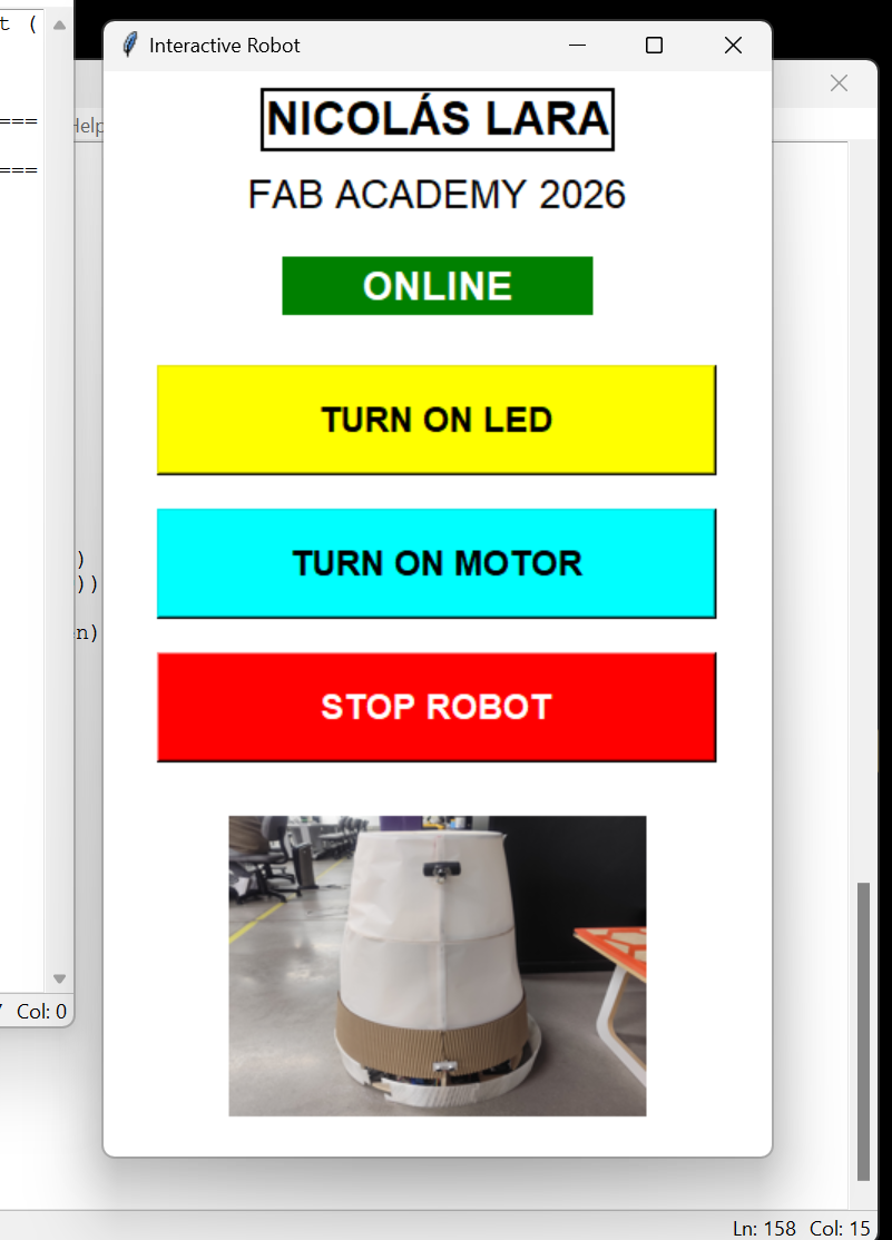
This is how my application turned out, which I will use from my computer.
Phase 9 ·
This is how my application works with my board
Conclusions
With this exercise, I learned to use App Inventor, which is a very useful and easy-to-use software for
creating mobile applications, especially when you want to control electronic devices.
The ESP32 board also allows us to connect via Bluetooth, which makes everything easier.
Creating an interface from Python is more complex, but it's useful for more complex projects.
← Main Page