What I did in Week 10
For this week I will use LEDs and a servomotor as output devices, which I will control with my ESP32 board.
- actuator: is a device capable of transforming energy (electrical, pneumatic, or hydraulic) into motion and mechanical force to activate or control an automatic process.
- Grupal: measure the power consumption of an output device
- Individual: add an output device to a microcontroller board you've designed, and program it to do something
Group page
Group page link
Output devices
Output devices are fundamental elements in electronic and automation systems, as they allow for the visualization or execution of physical actions based on signals generated by a microcontroller. Among the most common output devices are LEDs, motors, and displays. In this exercise, a basic control system was implemented using an ESP32 board, three LEDs simulating a traffic light, and an SG90 servo motor. The objective was to control the servo motor's movement based on the traffic light's status, simulating a basic signaling system used in industrial automation.
Phase 1 ·
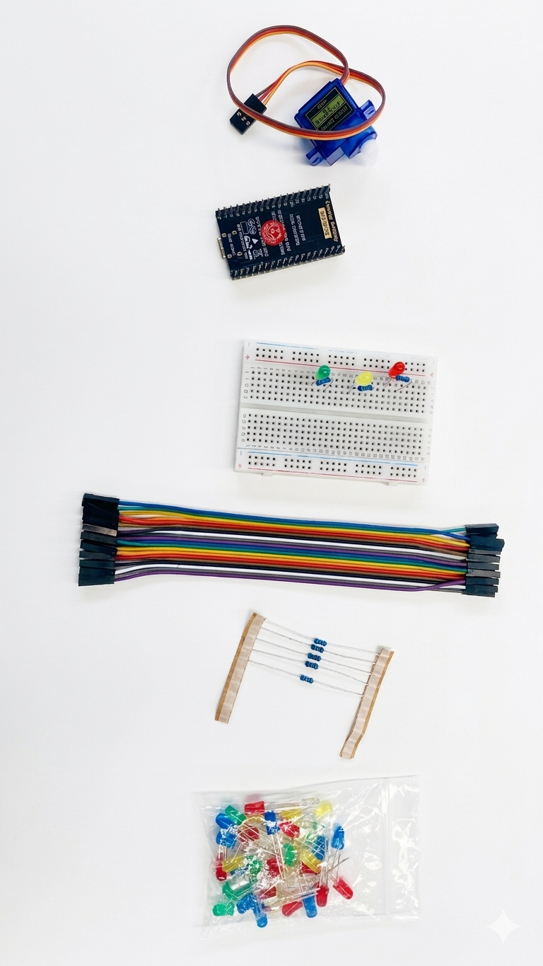
The materials used were:

Phase 2 ·
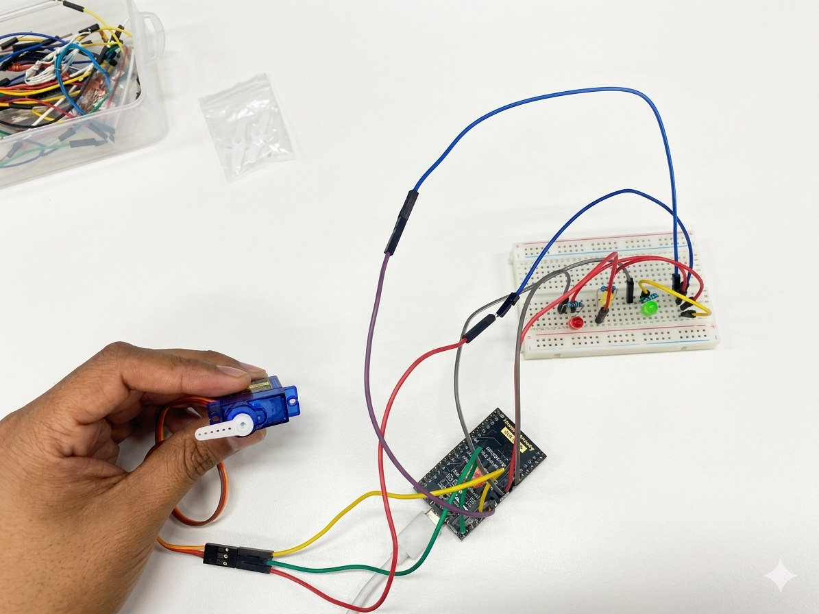
First, the LEDs (red, yellow, and green) were connected to the ESP32's digital pins using resistors to protect the components. Then, the SG90 servo motor was connected, using a 5V power supply, GND, and a PWM pin for position control.

Phase 3 ·
The program was then developed in the Arduino IDE using the ESP32Servo library, which allows control of the servo motor's angular position via PWM signals generated by the ESP32. To see the complete code, you can download the files at the bottom of the page.
Phase 4 ·
The code implements the following operating logic: when the red LED is on, the servomotor remains stationary in its initial position. When the yellow LED is activated, it flashes as a warning signal, indicating that the system is about to start. Finally, when the green LED is on, the servomotor activates, performing two rapid movement cycles from 0° to 180° and returning to its initial position. The system then repeats this sequence continuously.
Phase 5 ·
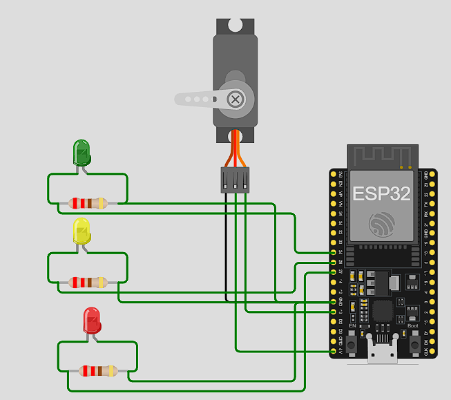
We can look at the electronic schematic to see the connections.
As a result, the output devices were successfully controlled using the ESP32. The correct operation of the LEDs indicating the different system states was observed, as well as the controlled movement of the servomotor when the green LED was active. Furthermore, it was verified that the servomotor responds correctly to the PWM signals sent by the ESP32 and that the programmed sequence executes repetitively without errors.
Conclusions
It is concluded that the ESP32 allows for the efficient control of various output devices, such as LEDs and servomotors, through programming. Furthermore, the importance of sequential control in automated systems was understood, as well as how output devices can represent the operating states of a system.
← Main Page