What I did in Week 04
We will learn the theoretical part of how microcontrollers work, we will write code, simulate, and build.
- Programming: process of writing instructions in code that allows a device to perform tasks
- Microcontroller: device to control specific tasks as instructed
- Sensors: element that detects physical or chemical changes and transforms them into electrical signals
- Actuadors: element that transforms energy into physical movement or force
- Group: demonstrate and compare the toolchains and development workflows for available embedded architectures.
- Individual: browse through the data sheet for a microcontroller.
- Individual: write and test a program for an embedded system using a microcontroller to interact and communicate
- Extra credit: assemble the system.
Group page
Group page link
ESP32 Datasheet
The ESP32 is a very versatile microcontroller that offers up to 34 digital GPIO pins and 18 analog pins, allowing a wide range of connections with sensors, actuators, and other electronic modules.
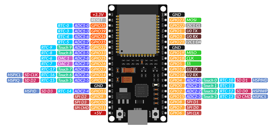
Phase 1 · ESP32 Technical specifications.
The heart of the ESP32 is a high-performance microcontroller designed to handle complex tasks and wireless connectivity, making it ideal for IoT projects and embedded systems. Its capabilities allow for rapid data processing and the simultaneous control of multiple devices.
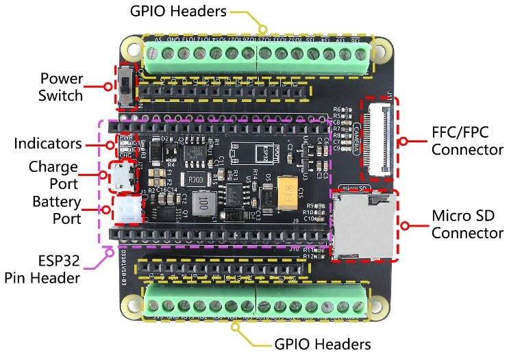
Phase 2 · Main components of the board.
The heart of the ESP32 is a high-performance microcontroller designed to handle complex tasks and wireless connectivity, making it ideal for IoT projects and embedded systems. Its capabilities allow for rapid data processing and the simultaneous control of multiple devices.
Embedded Programming
In this exercise, an automatic speed control system for a brushless motor was implemented using an ESP32 board, an electronic speed controller (ESC), and an HC-SR04 ultrasonic sensor. The objective was to regulate the motor's speed based on the distance detected by the sensor, simulating a proximity-based automatic control system. The ESP32 was used as the main processing unit due to its ability to generate PWM signals and its versatility in automation and embedded systems applications. The ultrasonic sensor allowed distance measurement using the time-of-flight of ultrasonic waves, while the ESC allowed the brushless motor's speed to be controlled using servo-like signals.
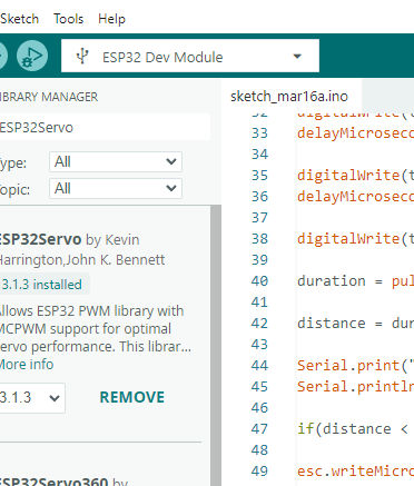
Step 1 · Load the code
The code was developed and executed in the Arduino IDE programming environment version 2.3.3, which allowed the compilation and uploading of the program to the ESP32 board. As a first step, it was necessary to correctly select the board model (ESP32 Dev Module) and the corresponding communication port from the Tools menu, in order to guarantee correct communication between the computer and the microcontroller.
#include

Servo esc;

int escPin = 18;

int trigPin = 5;
int echoPin = 17;

long duration;
float distance;

void setup() {

Serial.begin(115200);
pinMode(trigPin,OUTPUT);
pinMode(echoPin,INPUT);
esc.attach(escPin,1000,2000);
esc.writeMicroseconds(1000);
delay(5000);
             }

void loop(){

digitalWrite(trigPin,LOW);
delayMicroseconds(2);
digitalWrite(trigPin,HIGH);
delayMicroseconds(10);
digitalWrite(trigPin,LOW);
duration = pulseIn(echoPin,HIGH);
distance = duration * 0.034 / 2;

if(distance < 10){
esc.writeMicroseconds(1000);
}
else if(distance < 20){
esc.writeMicroseconds(1150);
}
else{
esc.writeMicroseconds(1300);
}
delay(500);
          }
Step 2 ·Code
This code allowed the distance to be measured and the motor speed to be controlled:
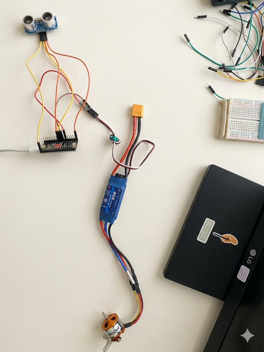
System implementation
In this section we will implement our system with the actual electronic components
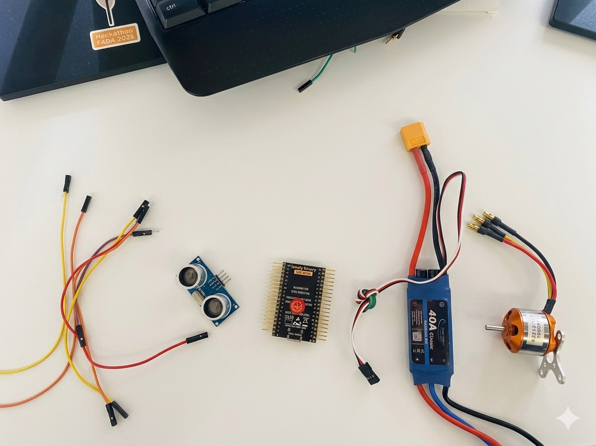
Step 1 · Used items.
The materials used for the implementation of the system were the following:
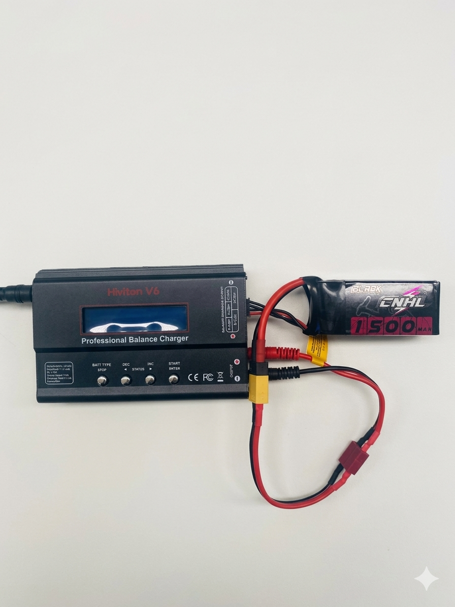
Step 2 · Energy source.
The system was powered by an 11.1V LiPo battery for the motor, while the ESP32 was powered via the computer's USB port to ensure stability during programming and testing.The LiPo battery must be fully charged for the activity to work correctly.
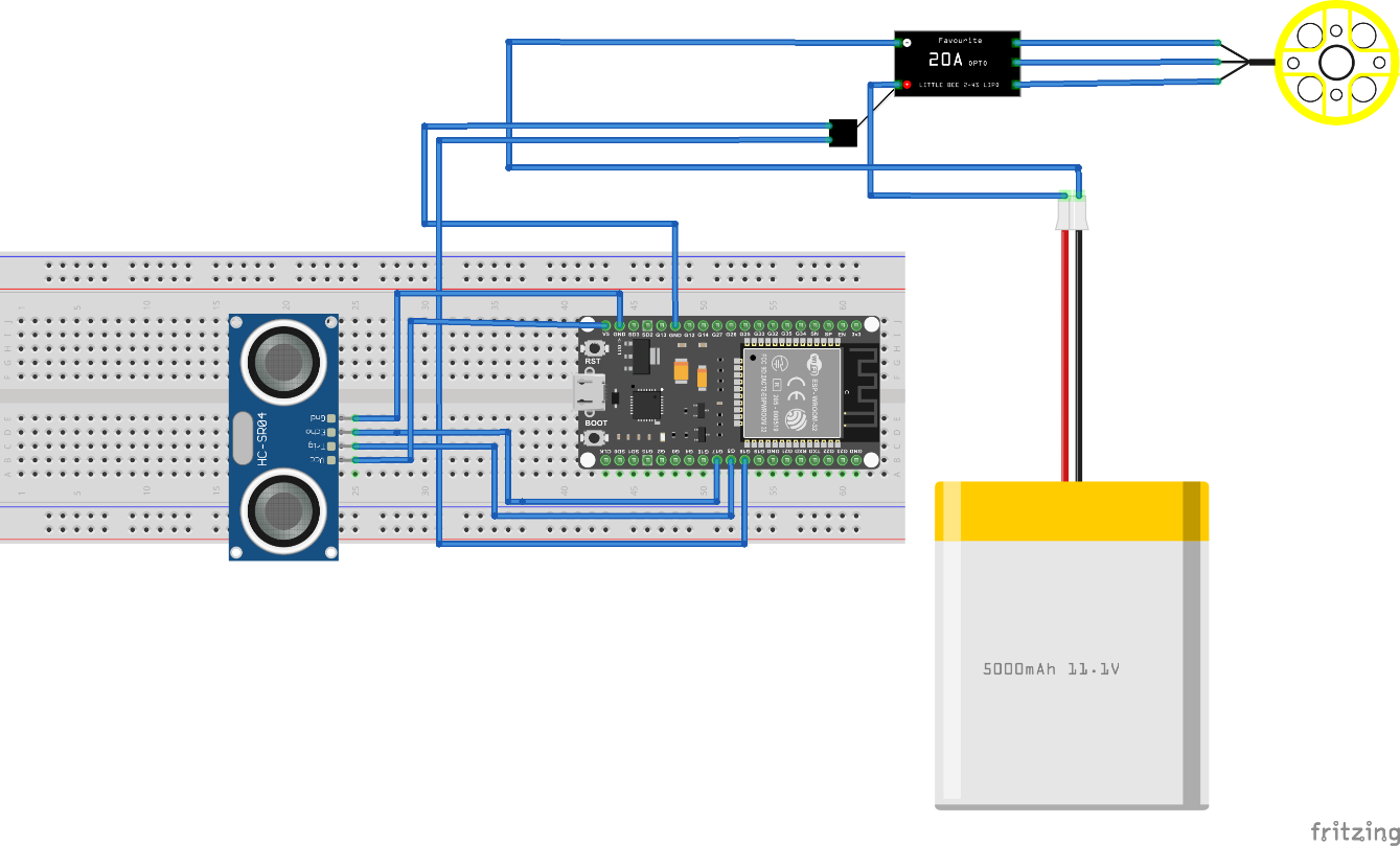
Step 3 · Connection diagram
The system connections were made as follows:
Workflow.
The procedure followed during the lab was as follows:
System operation.
The system works by continuously measuring the distance detected by the ultrasonic sensor. The ESP32 sends a pulse to the sensor and measures the response time to calculate the distance. Depending on the detected distance:
Results obtained.
During the experiment, the correct operation of the automatic control system was verified. The ultrasonic sensor accurately detected the distance to objects, and the ESP32 processed this information to control the motor speed. It was observed that the motor responded appropriately to changes in distance, decreasing its speed when an object approached and increasing it when it moved away. The importance of proper ESC assembly and correct system power supply was also confirmed. As a final result, a functional sensor-based automatic control system was obtained, demonstrating the practical application of microcontrollers in industrial automation and control systems.
Conclusions
This week I reinforced my knowledge of embedded systems programming and how software interacts directly with electronic hardware. When programming microcontrollers, you learn to upload code, configure development environments, and control inputs and outputs so the board performs specific tasks. Troubleshooting issues such as incorrect pin configurations, connection problems, and programming errors improved my logical thinking and problem-solving skills.
← Main Page