What am I imagining ?
Automated Assistant for Collaborative Culture at Universidad Indoamérica
Final video
Introduction
The Technological Campus of Universidad Indoamérica, understood as a living laboratory of experimentation and co-creation, provides the social and spatial ground for introducing the Automated Assistant as more than a technical device: it is conceived as an open, social-robotic platform that mediates relationships between people, knowledge, and machines. In this initial phase, the project does not aim to deliver a fully resolved product, but to define an interaction framework in which the robot becomes an empathetic companion embedded in everyday academic life—accompanying students during prototyping, supporting faculty in pedagogical dynamics, and assisting technical teams in their workflows. Its behavior is deliberately human-centered, even within a limited interface: interaction with users occurs through sound cues and commands issued from a mobile application, enabling the community to direct its movements, trigger messages, or request assistance in specific tasks. As campus communities—executives, teachers, technicians, and especially students—appropriate the assistant, they configure tasks, script new behaviors through the app, and effectively “train” the robot, turning it into a shared, evolving interface for collaboration. In doing so, the Automated Assistant catalyzes social-technological dynamics that transform the campus into a distributed ecosystem of social innovation, where technological intelligence and situated human practices jointly reshape how learning, creativity, and sustainability are enacted in everyday academic life.
Project Objective
To propose the Automated Assistant, a social robot conceived as an empathetic and collaborative agent within Universidad Indoamérica’s Tech Campus, integrated as an open platform that mediates interactions between laboratories and their communities. In this initial phase, the project focuses on defining its role, behavior, and interaction logic—through sound cues and app-based commands—to foster collective experimentation, enrich learning experiences, and strengthen meaningful interaction between users and technological assistants. By combining human-centered design with emerging technologies and enabling campus users to configure and co-evolve its functions, the initiative aims to cultivate a more connected, inclusive, and innovative academic environment.
Design methodology / Vision in product design
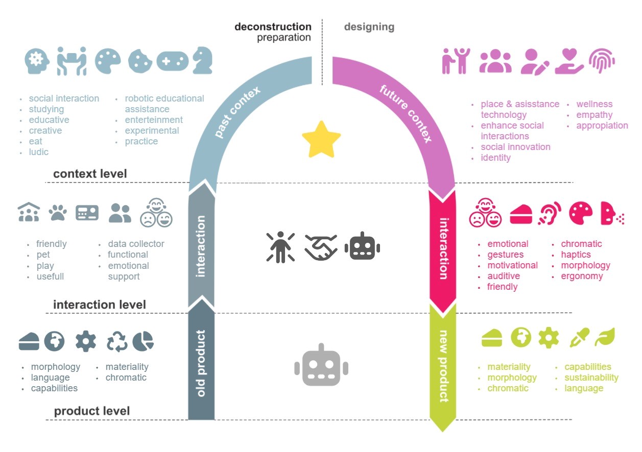
ViP is a design approach grounded in three fundamental premises. First, it conceives design not as an activity aimed at solving existing problems, but rather as a speculative practice that explores possibilities and desirable futures. Second, it understands products not as ends in themselves, but as vehicles for enabling meaningful actions, interactions, and relationships; it is precisely through their interaction with people that artifacts acquire meaning, placing interaction at the core of the ViP approach. Finally, it holds that the relevance of such interactions is intrinsically tied to the context for which they are designed whether that context be the contemporary world, near-future scenarios, or longer-term visions all of which demand new modes of behavior and engagement. For these reasons, ViP is fundamentally context-driven, with context serving as the guiding axis of the design process. It should be emphasized that ViP does not constitute a prescriptive methodology that rigidly dictates what to do and when to do it. Rather, it functions as a conceptual framework and a flexible approach that guides how a design task is addressed, offering guiding principles instead of fixed procedures.
Context level
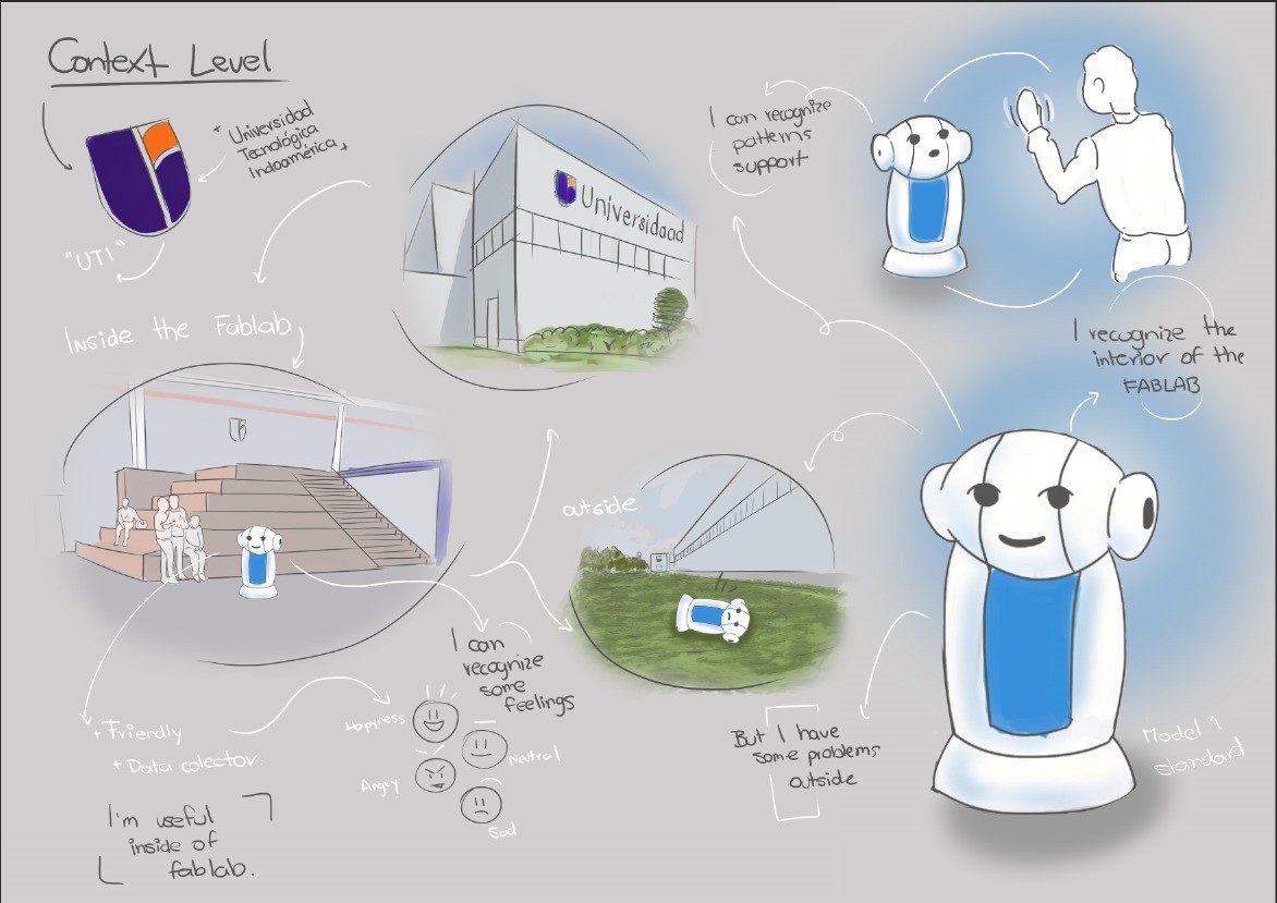
The context level emerges organically from the interaction level, shifting focus away from the specific product toward the social, cultural, and situational conditions that render it meaningful. In this phase of deconstruction, the aim is not merely to describe how a person-product interaction occurs, but to investigate the underlying factors economic, emotional, historical, or symbolic that enable it and give it significance. Applied to the environment of the Technological Campus of Universidad Indoamérica a dynamic space dedicated to experimentation, co-creation, and innovation this contextual approach reveals why a social robot cannot be designed solely through a technical lens. Its form, modes of communication, and responsiveness must reflect the genuine needs of an academic community that seeks more than efficiency: it yearns for connection, empathetic companionship, and experiences that resonate on emotional and sensory levels. Thus, just as every meaningful product arises from a complex web of contextual conditions, this robot is conceived as a sensitive response to a historical moment in which technology must transcend mere functionality to nurture human well-being and strengthen creative collaboration.
Interaction level
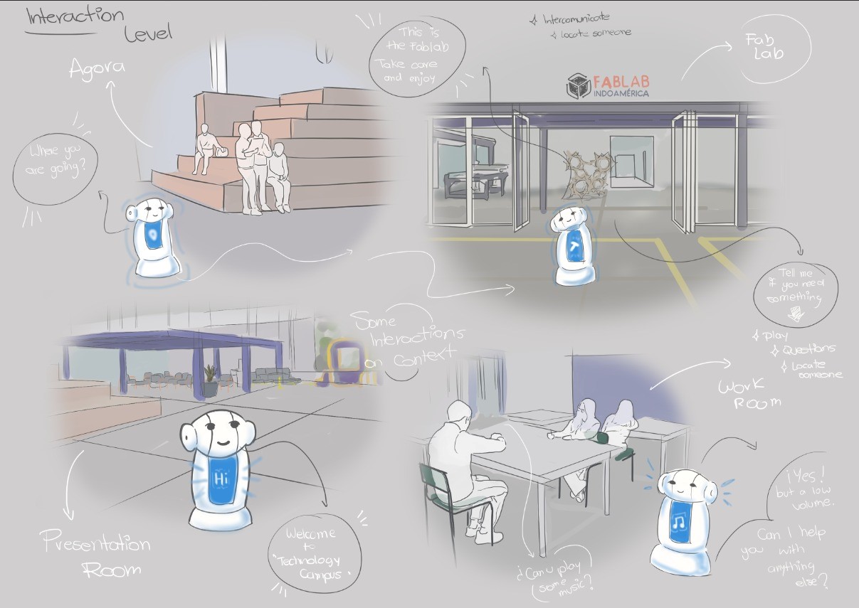
In truth, meaning emerges in the interaction between a person and a product for instance, a social robot. This dynamic is far more complex than it might initially appear. From the ViP perspective, a product’s value does not lie in its technical features or in the user’s intentions considered separately, but rather in the quality of the relationship they co-create. That quality resides neither in the robot nor in the person in isolation, but in the relational space that unfolds between them. To better grasp this idea, consider your relationship with someone close to you a friend, a family member, or even a pet. If you try to describe it in just a few words trust, companionship, support, empathy you’ll notice these qualities do not belong to either individual alone, but to the relationship itself. Similarly, interaction with a social robot is not merely about executed commands or preprogrammed responses; its true value arises in that living exchange, in mutual adaptation, and in the emotional or functional resonance that develops. The key insight here is recognizing that this relationship is not a physical object one can point to; it exists neither in the robot nor in the human, but in the intangible space that connects them. While it could not exist without both participants, it transcends their individual boundaries, dwelling in that “in-between” where genuine meaning is woven.
Product level
This way of thinking central to the first half of ViP, known as Deconstruction seeks to uncover the underlying factors that shape how products come to be, prompting us to ask: Why are products the way they are? To answer this question, we must step back from the surface-level world of objects and move from asking what a product is or does, to questioning why it exists in that particular form and function. Applied to the development of our social robot, this deconstructive stance invites us to look beyond conventional notions of assistive technology. Rather than starting with assumptions about what a robot “should” do such as giving instructions or automating tasks we interrogate the deeper social, emotional, and contextual conditions that give rise to meaningful human robot interaction. Why should the robot speak? Why express emotions through light or touch? Why prioritize adaptability over efficiency? By shifting focus from what the robot is to why it is needed in this specific collaborative environment, we ground its design in the lived realities of students, educators, and technicians at the Technological Campus of Universidad Indoamerica. Thus, Deconstruction becomes the essential first movement in shaping a robot not as a mere tool, but as an empathetic participant in a shared ecosystem of learning and innovation.
Designing and conceptualizing
A social robot is envisioned for the Technological Campus of Universidad Indoamérica—a dynamic environment dedicated to experimentation, co-creation, and innovation—not as a technical tool, but as an empathetic companion that will enhance human connection through emotionally intelligent technology. This robot will support the university community by fostering collaboration and collective innovation.
Its human-centered design will enable it to recognize emotions, convey moods through expressive lighting, offer encouragement through supportive language, and feature a tactile, inviting form. It will continuously learn from every interaction, adapting empathetically to the evolving needs of those around it. Its physical realization will be achieved through digital fabrication technologies, incorporating principles of open design, sustainability, and accessibility inherent to the campus’s technological ecosystem.
In everyday campus life, the robot will act as a present and responsive collaborator: accompanying students during hands-on experimentation and daily activities through emotionally attuned interactions that strengthen their creative confidence. The outcome is expected to be an adaptable artifact whose morphology, aesthetics, and communication seamlessly blend functionality with sensitivity. More than a utilitarian device, it will redefine the academic environment as a living ecosystem of social innovation—enriching learning, amplifying creativity, and reinforcing a collaborative spirit toward a more humane, sustainable, and effective future.
Why we're building it
Two simple ideas sit at the heart of this project. Everything else — the wheels, the compartments, the lights — exists to serve them.
Make a robot feel normal
The goal isn't to show off technology — it's to let people get used to it. By giving the park a friendly robot that's simply around every day, students, faculty, and visitors slowly learn to share space with it: to pass it in a corridor, hand it a package, and read what it's doing without a manual. Familiarity is the feature. Over time, meeting a robot on campus stops being a novelty and becomes just another part of the day.
Open a platform to build on
The assistant is designed to be handed off and grown. Its body, electronics, and behaviour are modular on purpose, so the next student, the next class, the next lab can add a new function without rebuilding the core. It's an invitation: a real, rolling problem the community can keep exploring — a canvas for ideas that don't exist yet. What it does tomorrow is up to whoever picks it up next.
The design processHow the idea took shape
| ViP Level | Past Context | Future Context |
|---|---|---|
| Context | Separate laboratories and fixed technical spaces. | The Technological Park as a living laboratory for collective experimentation. |
| Interaction | Static, fragmented, and one-way assistance. | A screen-free assistant using movement, light, sound, and app commands. |
| Product | A closed technical device with fixed functions. | An open social-robotic platform co-developed by the campus community. |
The idea of the Automated Assistant took shape precisely through the kind of shift that the ViP framework describes: from an “old product/past context” to a “new product/future context,” rethinking context, interaction, and product together. At the context level, the starting point was a conventional view of the Technological Park as a collection of specialized labs and high-tech equipment mainly used to deliver courses, execute projects, and showcase institutional innovation. The future context reframes the park as a working laboratory in itself, where the community continuously prototypes how technology, space, and social life intertwine. In this new context, value is not only in machines but in the ongoing, shared process of configuring how those machines—and now robots—participate in everyday academic culture. At the interaction level, the “old product” would be a tool-centered assistant: a screen-based interface or static kiosk that provides information, schedules, or wayfinding on demand. The Automated Assistant instead is imagined as a screen-free companion that communicates through movement, light, and soft sound, following learned routes and responding to app-triggered commands. Interaction becomes spatial and collective: different groups design behaviors, define paths, and decide what the robot communicates, transforming use into co-authorship. The assistant is not only giving answers; it is a medium through which the community experiments with new social-technological rituals. At the product level, the earlier imagination of a “service robot” is deconstructed into an open creative platform. Rather than a finished device delivered to users, it is a programmable, fabricable artifact whose hardware, casing, and behaviors can be incrementally redesigned. Each function—guiding between labs, announcing events, supporting a class, carrying material—becomes a pretext for students, faculty, and technicians to design, prototype, and add “a piece of the whole.” This cumulative authorship is what allows the assistant to embody Universidad Indoamérica’s identity as Ecuador’s first Technological Park of Innovation and Entrepreneurship: a campus where technology is made by, with, and for its community, and where building the robot is part of building the campus’s technological future.

Why a social robot, here?
The context level looks past the device to the social, cultural, and emotional conditions that make it meaningful. On the Technological Campus — a space for experimentation, co-creation, and innovation — the community wants more than efficiency: it wants connection, empathetic companionship, and experiences that resonate. The robot is framed as a sensitive response to that moment, not just a technical tool.
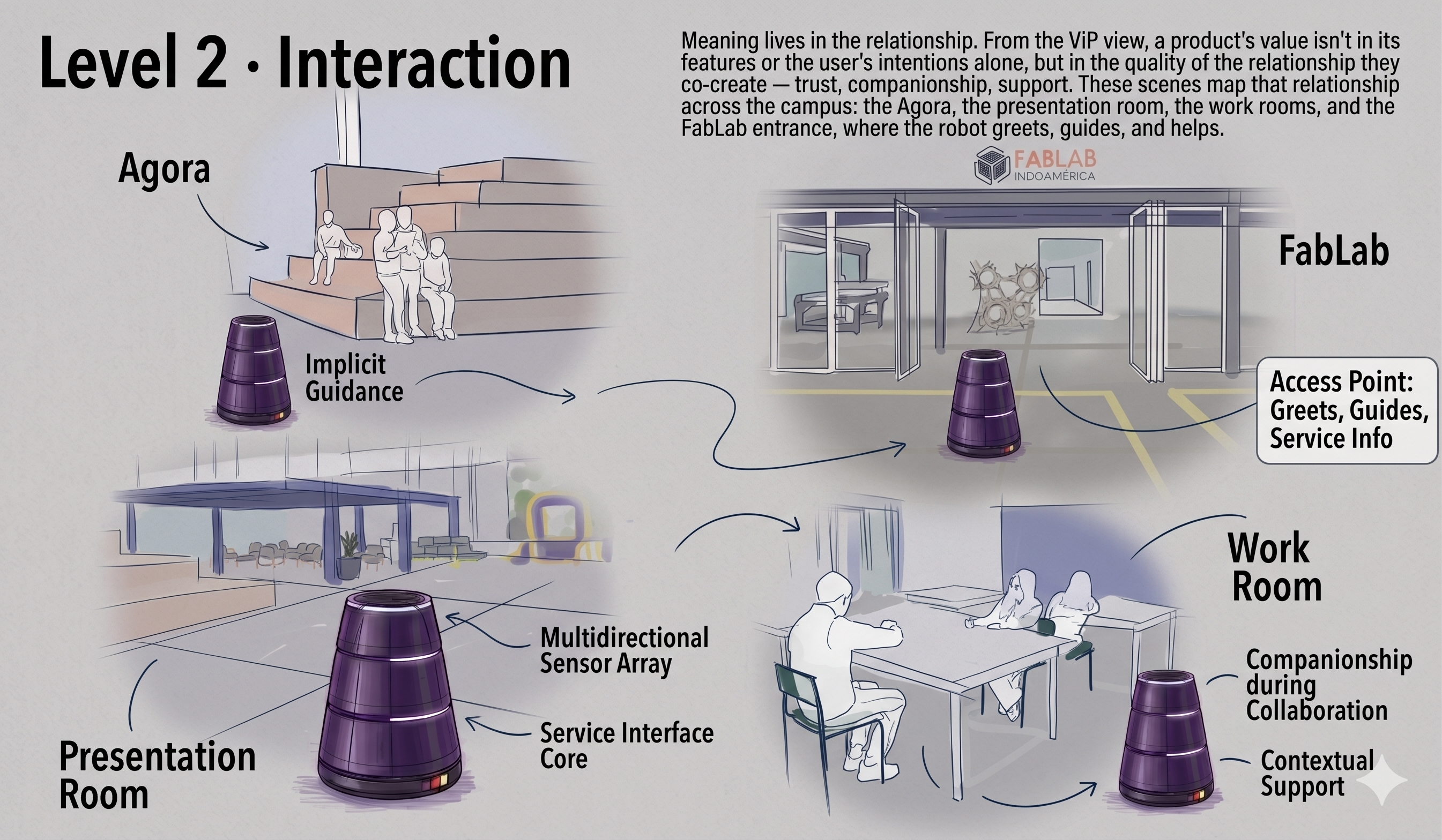
Meaning lives in the relationship
From the ViP view, a product's value isn't in its features or the user's intentions alone, but in the quality of the relationship they co-create — trust, companionship, support. These scenes map that relationship across the campus: the Agora, the presentation room, the work rooms, and the FabLab entrance, where the robot greets, guides, and helps.
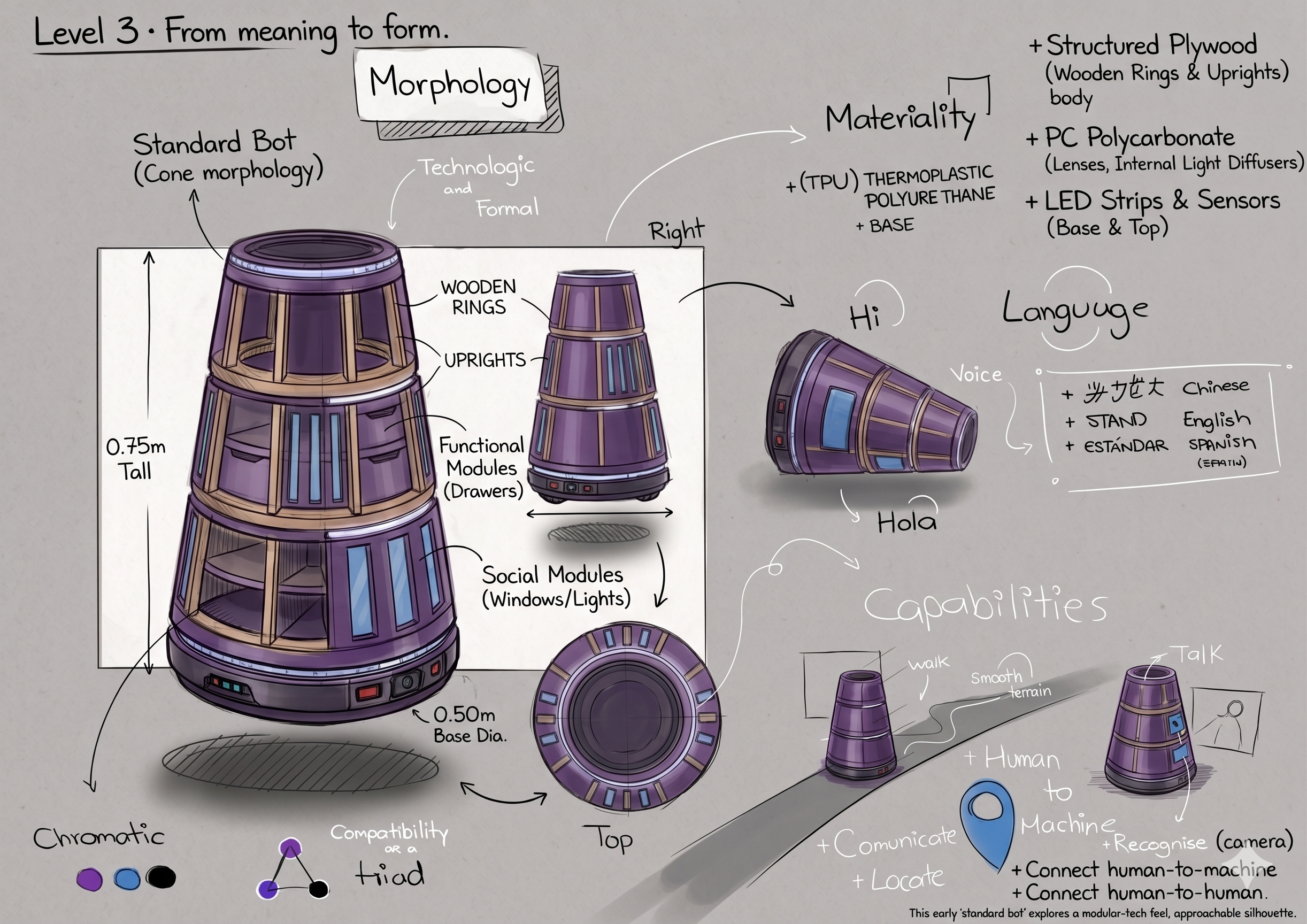
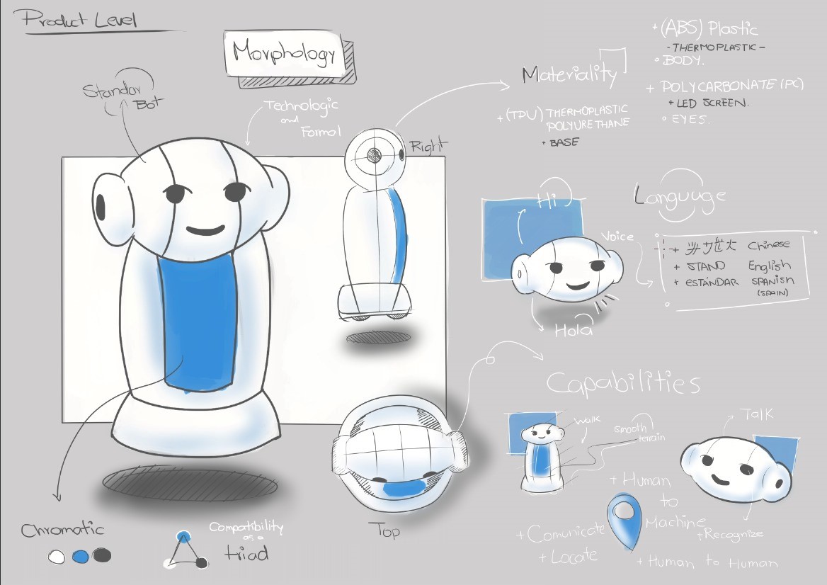
From meaning to form
Only now does form appear. The product level translates the desired interaction into morphology, materiality (ABS, polycarbonate, TPU, an LED “face”), an adaptable language (Spanish / English), and capabilities — recognising, locating, connecting human-to-machine and human-to-human. This early “standard bot” explores a friendly, approachable silhouette.
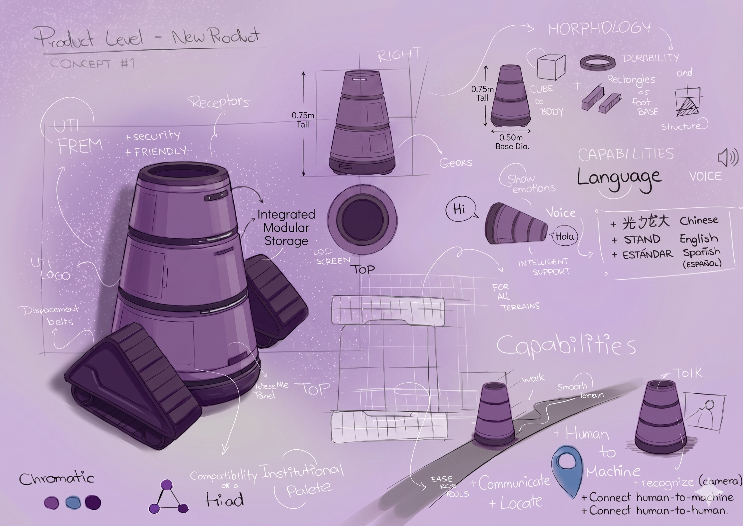
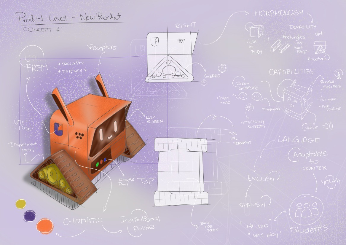
The first concept
A first resolved concept: an expressive, treaded body in the UTI institutional palette, with a screen-free LED face, displacement belts for all terrains, a tool bay, and an interactive panel. Studies cover morphology, capabilities (show emotions, request help, find someone), and an adaptable youth-friendly language.
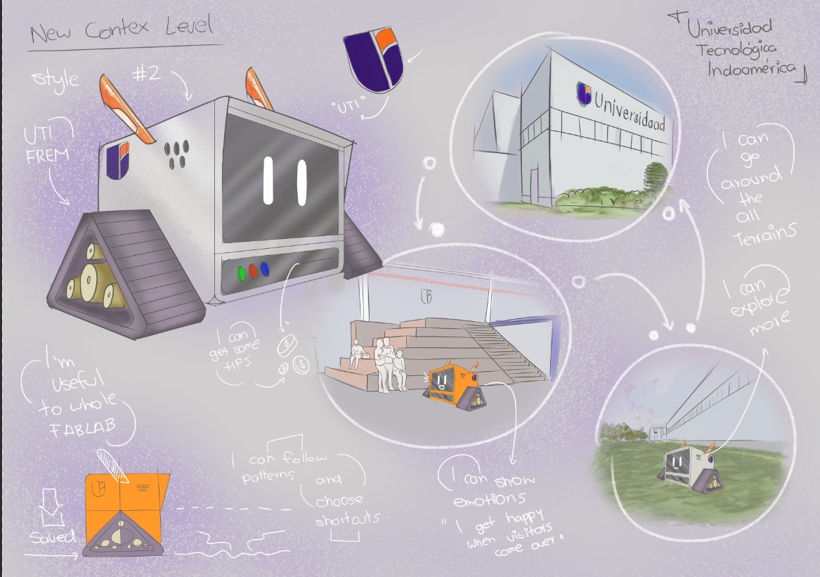
Universidad Indoamérica Tech. Context.
The diagram of Universidad Indoamérica’s Tech Park reveals a linear sequence of highly specialized laboratories—ranging from the Fab Lab, construction and carpentry areas to mechatronics, robotics, bio-cam, automation, virtual reality, digital media, electrical machines, and basic sciences—connected by a continuous circulation where the Automated Assistant, a social robot, is proposed as a moving node. Within this spatial and programmatic layout, the initial intention of the project becomes clearer: the Automated Assistant can operate as a mobile, empathetic interface that physically travels along this route, linking labs that usually function as isolated “islands” into a shared experimental ecosystem. By following predefined paths and pausing in strategic interaction hubs, the Automated Assistant could announce ongoing activities, guide students between workshops, assist in documentation of projects, and encourage cross-pollination between disciplines—for example, connecting a VR prototype with a fabrication process in the Fab Lab, or a robotics experiment with bio-oriented research in the Bio-Camb. In this way, each laboratory is not only a technical resource but also a node in a distributed learning network, where the Automated Assistant choreographs encounters, supports collaboration, and makes the technological infrastructure of the Tech Campus more visible, accessible, and socially meaningful.
What it does from day one
The first stage keeps things simple and useful — a helpful presence that carries, informs, and serves the spaces where the park's ideas happen. These are the everyday moments that turn a robot into a familiar face.
📦Campus courier
Secure onboard compartments carry documents, samples, tools, and materials between distant labs and offices — opening only at the destination so contents stay safe.
🔧Parts & tool transport
Links the Robotics Lab, Fab Lab, and offices, ferrying boards, motors, sensors, and kits to where they're needed — fittingly, the courier of the very parts used to build robots like itself.
📌Mobile noticeboard
Carries posters, announcements, and QR cards that travel physically as it circulates — a moving channel that reaches every block, no screens required.
👀Maintenance scout
While moving, it flags little problems — a burnt-out light, a blocked path, an open door — and feeds a simple report, like an extra set of eyes around the park.
⏰Timekeeper
On its memorised routes, it marks the rhythm of the day — class changes, breaks, session starts — with friendly light and sound cues as it passes. A moving clock for the park.
🧭Onboarding buddy
For first-week students or new staff, it runs a gentle "follow me" tour past the key labs and service points — easy orientation that doesn't depend on anyone being free.
An open invitationWhere it could grow next
Once the basics are proven, the assistant becomes a platform for new ideas. These next roles aren't a fixed roadmap — they're possibilities waiting for someone to pick them up. Each one is a project a future team could design, build, and add.
🧴Supply runner
Notices when consumables, paper, or first-aid kits run low and carries the refill — closing a real loop without manual rounds.
🌡️Environment & safety monitor
Logs temperature, humidity, air quality, and noise as it travels; on critical readings, it speaks up with light and sound — a mobile early-warning layer.
📊Space-usage logger
Records which areas are busiest, quietly generating real data for planning, resources, and accreditation during everyday movement.
🔌Charging & tool station
Comes to you when your laptop dies — carrying outlets, USB ports, chargers, and clickers along its routes. A service people seek out.
🌙After-hours patrol
When the park empties, it lights dim areas, watches for motion or open doors, and logs its rounds — guide by day, gentle sentinel by night.
♿Accessibility guide
A dependable physical escort that leads visitors with reduced mobility — or anyone new — straight to where they need to go.
🧤Lost & found
A dedicated compartment collects found items and returns them to a central desk as it finishes its rounds — a mobile recovery system.
🖼️Roaming showcase
Displays rotating student and faculty work in a viewing compartment — a moving portfolio of the park's output for visitors and press.
🎉Event companion
At fairs and open houses, it takes a fixed-position role with playful light and sound that animate the space and generate content.
🏭Fab Lab helper
Integrates with the fabrication spaces to support material transport, equipment monitoring, and project workflows at the heart of the park.
🚀 This is your platform too
The assistant is built to be explored, extended, and reimagined. Whatever your discipline, there's a way in — and the best ideas for what it should become haven't been thought of yet. Here's where you could start:
Design & fabricate
Add a new compartment, attachment, or shell section using the Fab Lab.
Program a behaviour
Teach it a new route, a new light language, or a new function in code.
Add a sense
Bring a new sensor on board and give the assistant a new way to perceive the park.
Shape the experience
Study how people meet it, and design interactions that feel more natural.
Standing on shouldersWho has done what before
🚚 Delivery & service robots in shared spaces
Autonomous delivery robots are now common on campuses and in hospitals, hotels, and warehouses, carrying food, mail, or supplies along mapped routes. Their core lesson is simple: a robot earns its place through reliable, repeated usefulness — not novelty. They also reveal the challenge we inherit: how people share space with a machine that moves among them. Our courier and transport roles sit in this tradition, but reframed as a community tool rather than a purely commercial one.
🛎️ Guide & reception robots
Museums, airports, and institutions have used robots that greet, inform, and lead visitors. They taught the field that people respond strongly to expressiveness, predictability, and "personality" — and far less to raw technical power. Many leaned heavily on conversation and screens; we deliberately set that aside in favour of movement, light, and sound, taking the friendliness without the fragile chat layer.
🤖 Social robotics research
A large body of academic work studies how people adapt to living alongside robots — how trust, comfort, and acceptance build over time, and how a robot's behaviour decides whether a community embraces or ignores it. This is our closest precedent: it treats coexistence as something to be cultivated. Our goal of familiarising the community with a robotic presence until it feels natural places the project squarely in this line of work.
The planWhat I'll design & build
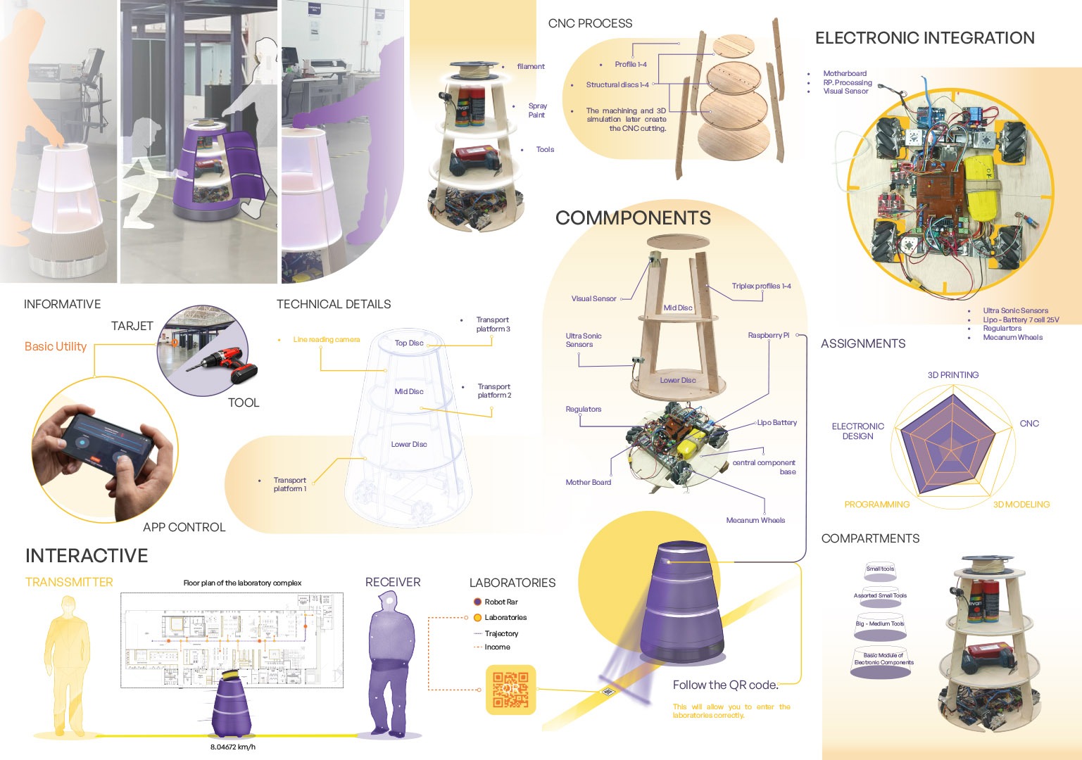
A robotic assistant from the ground up — a 70 cm omnidirectional cylinder bringing together a holonomic four-wheel drive, a layered structure, secure cargo compartments, an onboard compute-and-control system, a sensor suite for navigation and obstacle avoidance, and a light-and-sound signalling system, all in one coherent, approachable object. The real work is systems integration — making mechanical, electronic, control, and behavioural parts live together in a compact body that works reliably while sharing space with people.
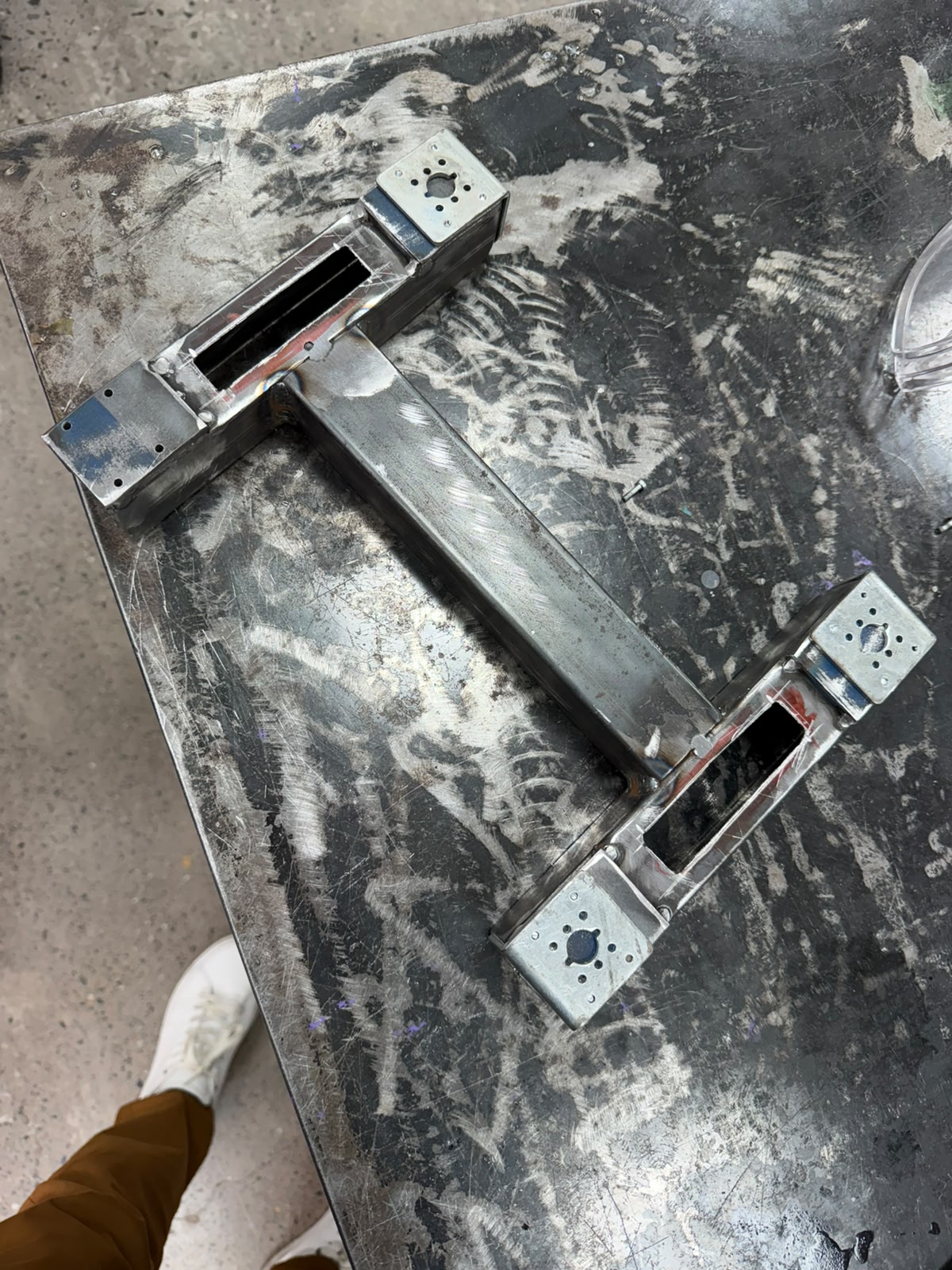
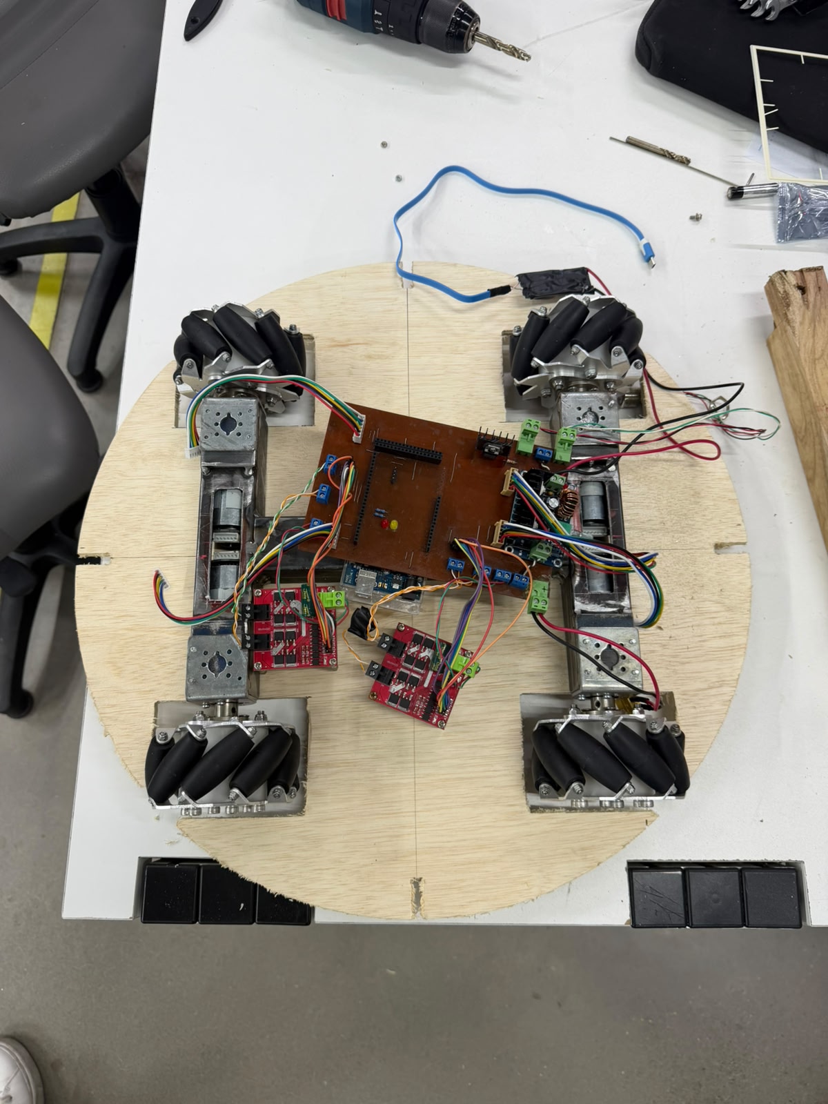
Chasis
The frame is a symmetric H-shaped (or I-shaped) structure: a central longitudinal beam of rectangular box tubing runs down the middle, and at each end a perpendicular crossmember branches out to form two opposing motor stations. The diagonal symmetry indicates a design for balanced, centered load distribution, consistent with a holonomic four-wheel layout where the wheels sit at offset positions around the body. At the two visible corners are flat mounting plates — galvanized/zinc-plated steel welded onto the brighter mild-steel tubing — each with a central bore for the motor shaft and a surrounding bolt pattern to fasten the gearmotor face, suited to omni or mecanum wheel motors. Rectangular cutouts in the box tubing near each mount allow for wiring routing or fastening access. The frame is hand-welded (visible beads at the beam-to-crossmember T-junctions, with grinding/brushing marks) and still bare metal, prior to any coating.
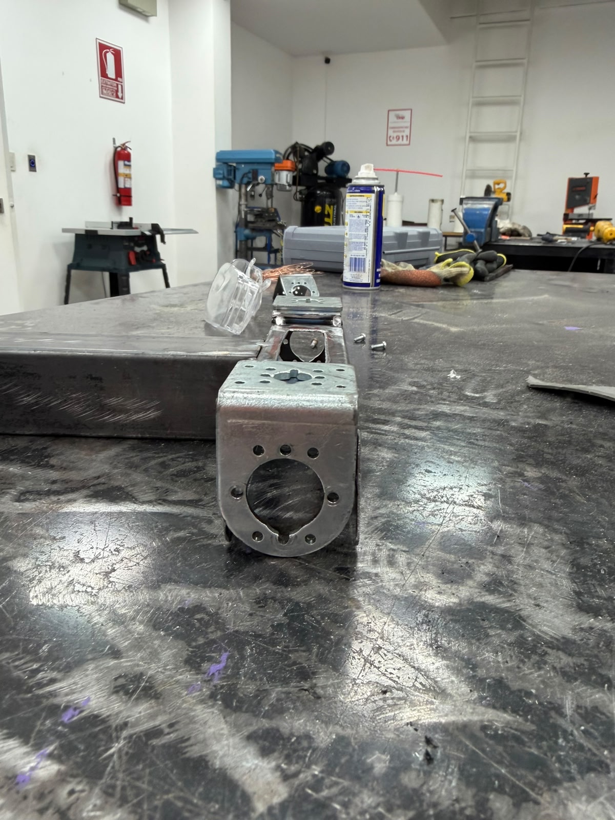
Chasis
This stage machines the interface that fixes each gearmotor and wheel assembly to the welded base frame: a large central bore for the motor shaft, ringed by a bolt pattern matching the gearmotor face. The positions are laid out and center-punched so the bit starts on location, drilled as pilot holes and opened to final diameter — the central bore stepped up through successive sizes (or a hole saw / step drill) since a large bit is hard to start on steel — using cutting fluid to reduce heat and protect the bit, with the loose fasteners on the bench used to test-fit against the real motor screws. Keep the plate square to the drill axis so bores come out perpendicular, drill both motor stations identically so the wheels end up coplanar and symmetric about the frame center, deburr every hole so the motor plate seats flat, and dry-fit the gearmotor with its actual fasteners before adding the upper subsystems.
Personalized Frame
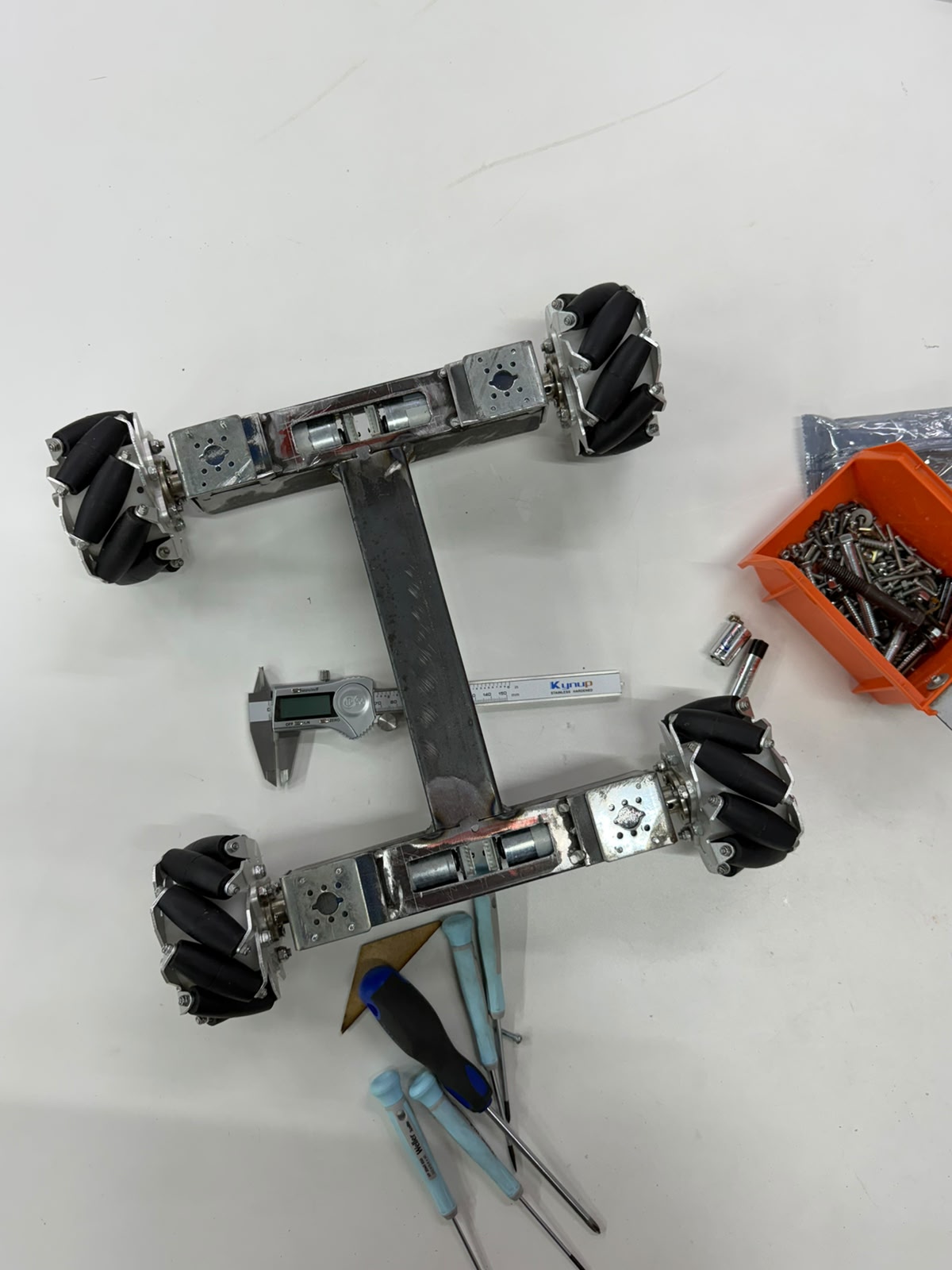
The key point is that the frame is not arbitrarily sized — its dimensions are derived from the powertrain itself. The cross-sectional width of the structural members is set by the diameter and mounting envelope of the wheel motors: each box-section crossmember must be at least as wide as the gearmotor body it supports, so that the motor seats squarely against its mounting plate and its shaft aligns concentrically with the wheel hub. In other words, the motor diameter establishes the minimum profile of the steel section, and the frame is built outward from that constraint to guarantee proper seating, shaft alignment, and clearance. The caliper measurement captured here is precisely this kind of fabrication check — confirming that the as-built member widths and mount spacings match the motor dimensions, that the four wheel stations are symmetric about the central spine, and that the resulting track and wheelbase preserve the coplanar, balanced geometry required for predictable holonomic motion. The result is a structure whose proportions are a direct, technical consequence of the components it carries, rather than a generic chassis adapted after the fact.
Drive frame with mecanum wheels
The image shows the assembled steel base frame fitted with its four mecanum wheels and gearmotors, laid out in the characteristic H-configuration: a central longitudinal spine bridging two transverse crossmembers, each terminating in a motor station that carries a face-mounted gearmotor and its mecanum wheel. The black angled rollers around each wheel hub are clearly visible, confirming the omnidirectional drive geometry, while the digital caliper and steel rule placed across the structure document the verification of critical dimensions during assembly.
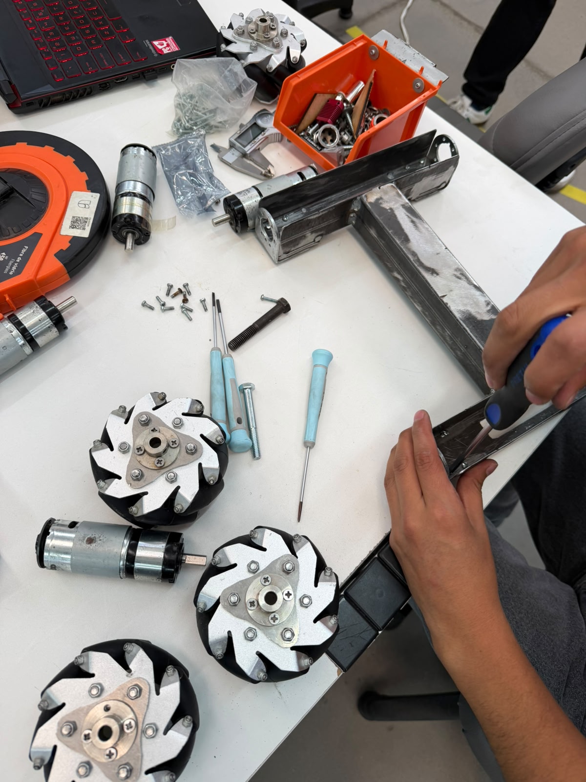
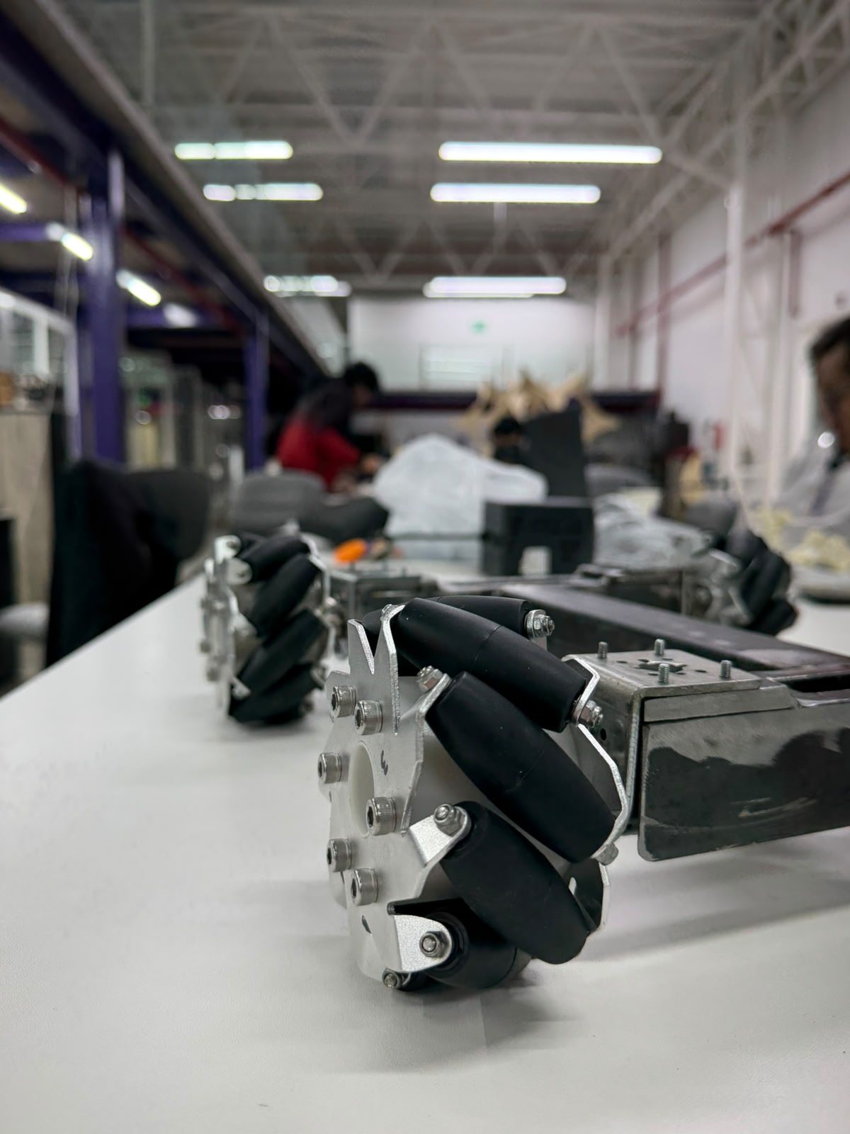
Omnidirectional Locomotion System
The assistant moves on four Mecanum wheels (often called "Mecano" wheels in the lab). Each wheel has a ring of rollers set at 45° to the hub, so the wheel can roll forward normally while also sliding sideways. When four of them are driven independently, the robot becomes holonomic: it can drive forward, strafe straight sideways, and rotate on the spot — or any blend of the three — without ever turning to face a new direction first. For a companion that has to glide politely through narrow corridors and slot into tight lab spaces among people, that ability to side-step is exactly the point.
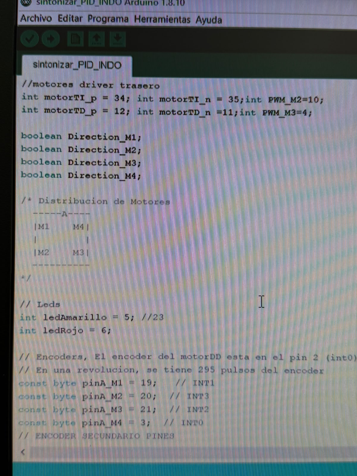
Low level Motion Control Programming
This is the opening section of an Arduino sketch that defines the pin assignments for the assistant's four-mecanum-wheel drive system. It declares the front and rear motor-driver control pins — where each motor uses a pair of direction pins plus a PWM speed pin, and four Direction M1–M4 boolean flags hold the running direction of each wheel. A commented diagram maps the four-wheel layout in an A-frame arrangement (M1 and M4 at the front, M2 and M3 at the rear), establishing the kinematic positions needed for omnidirectional mecanum movement.
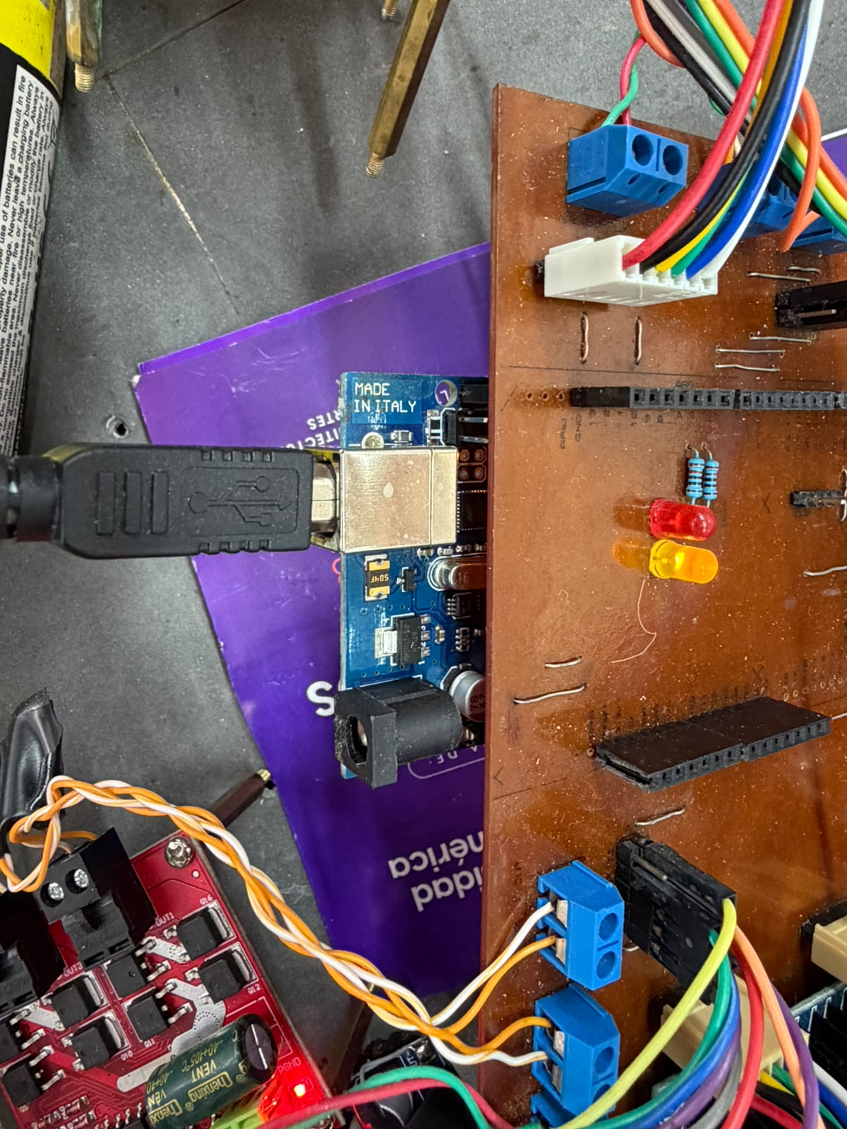
Custom control-board assembly for the locomotion system.
A custom-fabricated, milled copper-clad PCB acts as the central integration board for the robot's electronics, breaking out the pins of an Arduino-compatible microcontroller (Mega/Uno-class, USB type-B) into the rest of the drive system. The Arduino mounts directly into the board's female header strips and connects via USB for programming and bench power, while the custom board distributes those signals through blue screw terminals for power and motor lines, a keyed multi-pin connector routing the motor/encoder harness, two through-hole resistors, and the red and amber status LEDs defined in the firmware. From there, control and PWM signals pass to a multi-channel MOSFET/H-bridge motor-driver board — fitted with per-channel output terminals and a filter capacitor — linked by twisted wire pairs, which delivers the switched power that actually drives the mecanum-wheel motors under the microcontroller's command.
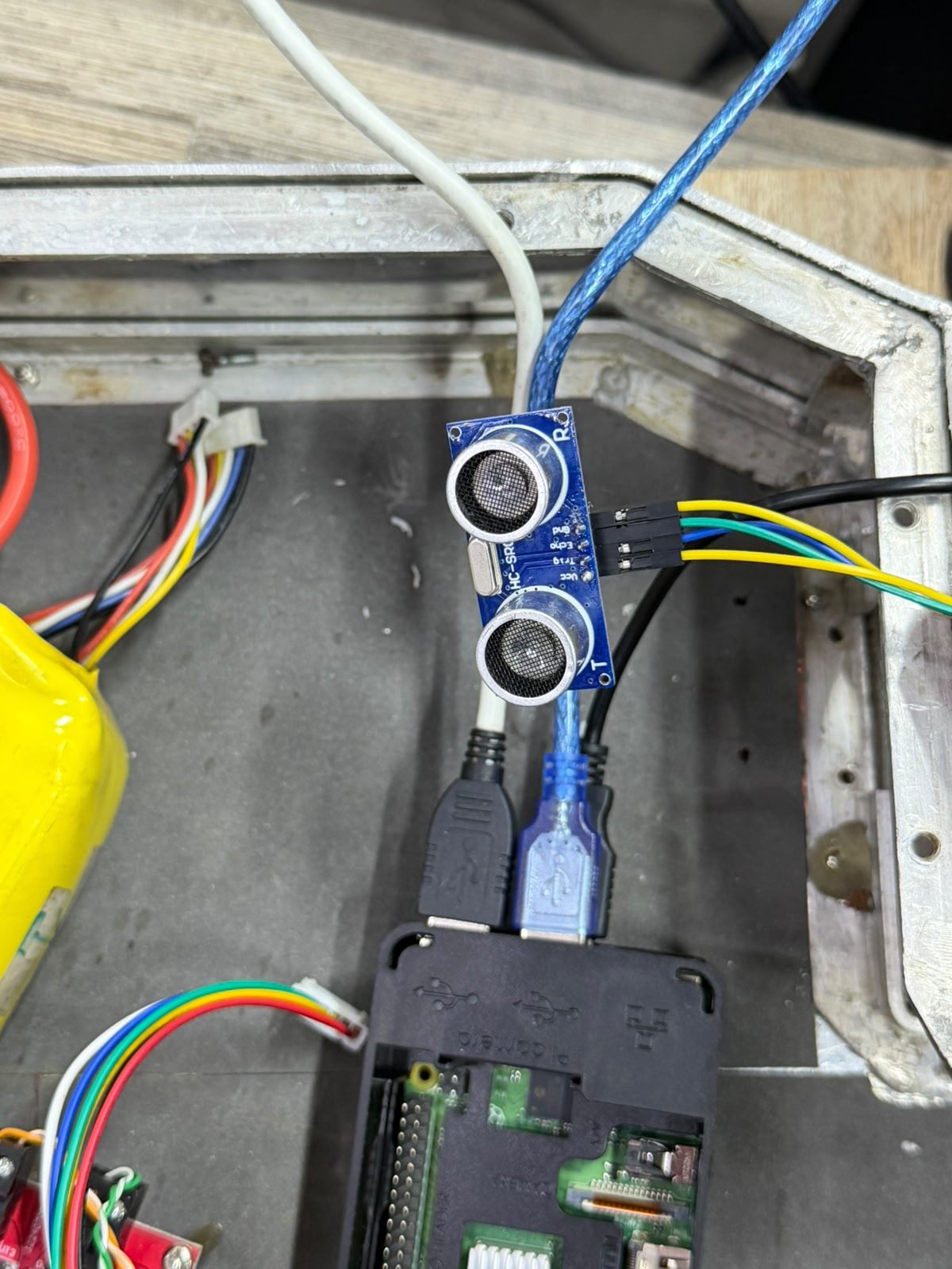
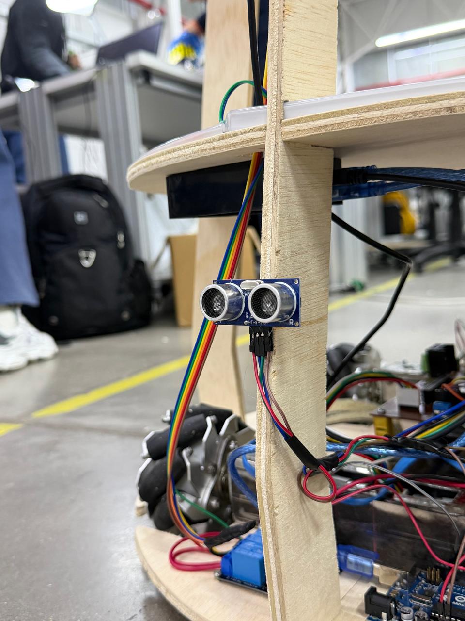
Ultrasonic distance-sensing subsystem.
The blue board is an HC-SR04 ultrasonic sensor, recognizable by its two metal-mesh transducer cylinders — one labeled T (transmitter) and one R (receiver) — flanking the crystal oscillator and "HC-SR04" silkscreen between them. Its four-pin header is wired through colored jumper leads following the standard pinout: Vcc (power), Trig (trigger input), Echo (echo output), and Gnd (ground), running back toward the controller. Functionally, this subsystem performs obstacle detection and ranging: the controller sends a short pulse to the Trig pin; the T transducer emits an ultrasonic burst, the R transducer receives the echo reflected off any object ahead, and the sensor returns a pulse on Echo whose width is proportional to the round-trip time of flight, from which the distance to the object is computed. Feeding this data into the robot's control logic lets the assistant sense objects in its path, evade obstacles, and brake when something is detected within its safety threshold — making it the primary proximity-sensing input for safe navigation.
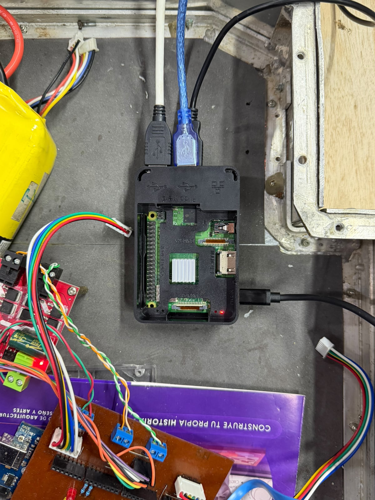
High level controller & Data acquisition.
At the center sits a Raspberry Pi single-board computer in a black case, identifiable by its 40-pin GPIO header, dual CSI/DSI flex connectors, HDMI and USB ports, and the white heatsink over the SoC, with its power LED lit. As the high-level controller and data-acquisition hub, it integrates all of the system's operational logic, compiling the input streams from the perception and signalling subsystems — ultrasonic ranging, the webcam-based vision/motion system, and the light-indicator status system — into a coherent picture of the robot's state. The white USB cable links it to the Arduino-class low-level controller and custom board (terminal blocks and twisted pairs running to the motor driver), carrying the commands and feedback that drive locomotion, while the blue USB cable runs to the ultrasonic subsystem, feeding the distance data that lets the assistant detect objects, evade obstacles, and brake. This two-tier architecture lets the Pi handle perception, logging, and decision-making while the microcontroller executes real-time motor control — making it the system's integration layer, powered and programmed through the cabling entering the case.

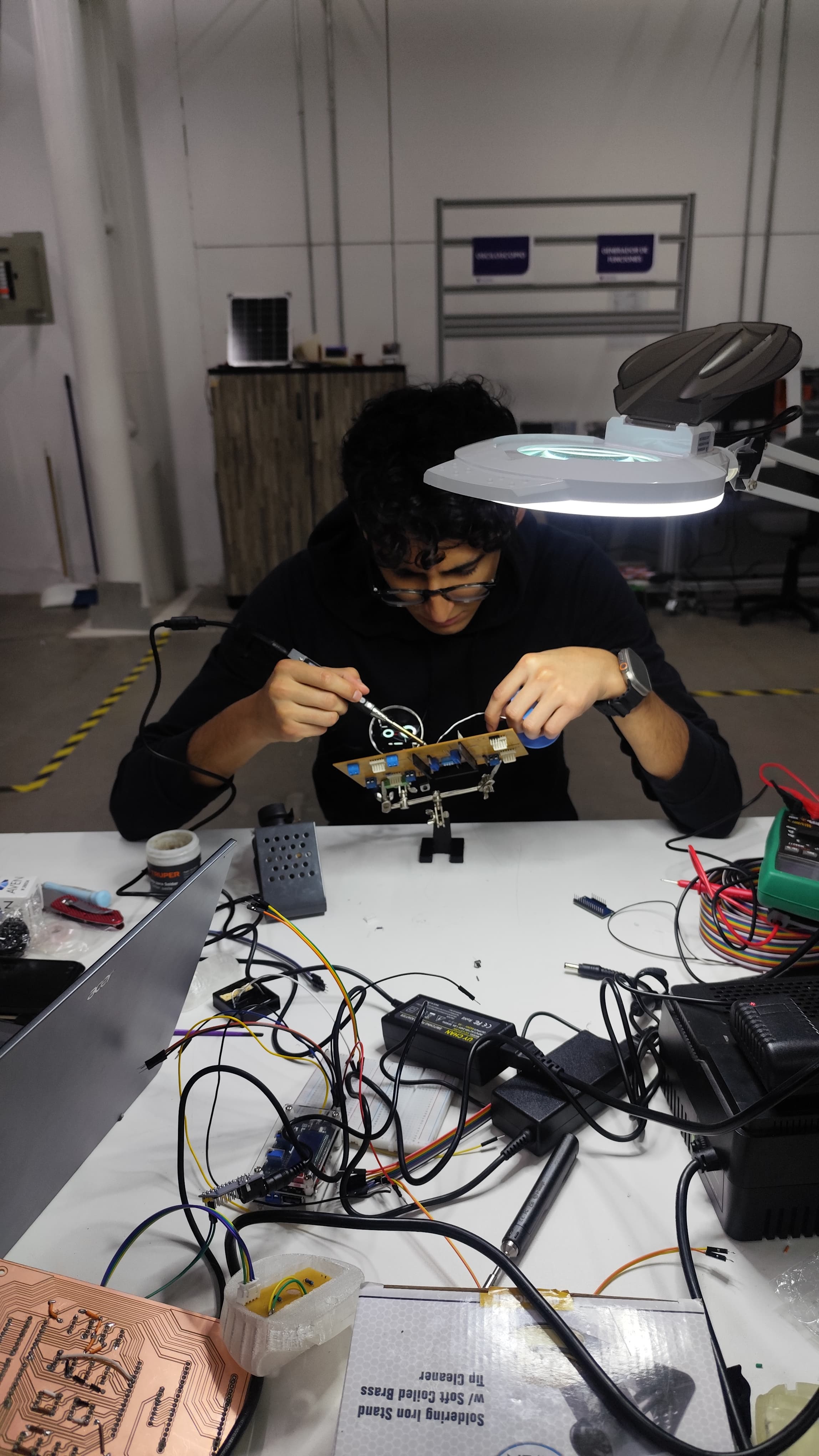
Fabricating and populating the custom control board.
In these two steps I produced the custom control board for the robot from scratch. First I milled the PCB: I clamped a copper-clad blank onto the CNC's sacrificial bed and let the machine route the circuit, watching the fine end mill cut the isolation traces and drill the pad holes directly into the copper, turning my board design into a physical, ready-to-populate PCB. This is the same milled board that becomes the central wiring and integration hub for the locomotion electronics. Then I moved to the bench to populate and assemble it. Working under a magnifier lamp with the board held in a soldering stand, I soldered the components into place — the screw terminals, headers, status LEDs, and the rest of the parts — building up the board that carries the microcontroller and ties together power, motor control, sensing, and signalling. Around me I had the full bench setup I was working with: the laptop with my design, the power supplies, the rainbow ribbon cable, the multimeter for checking continuity, and earlier milled boards. With this, I fabricated and hand-assembled the custom electronics that integrate the assistant's subsystems, taking the board from raw copper to a finished, functional unit.
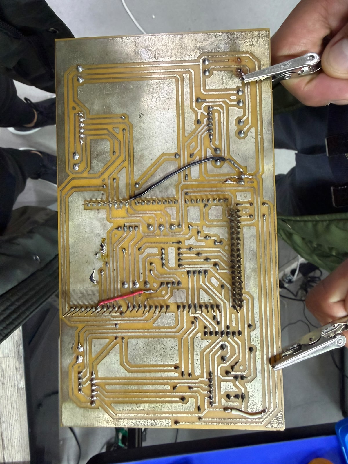
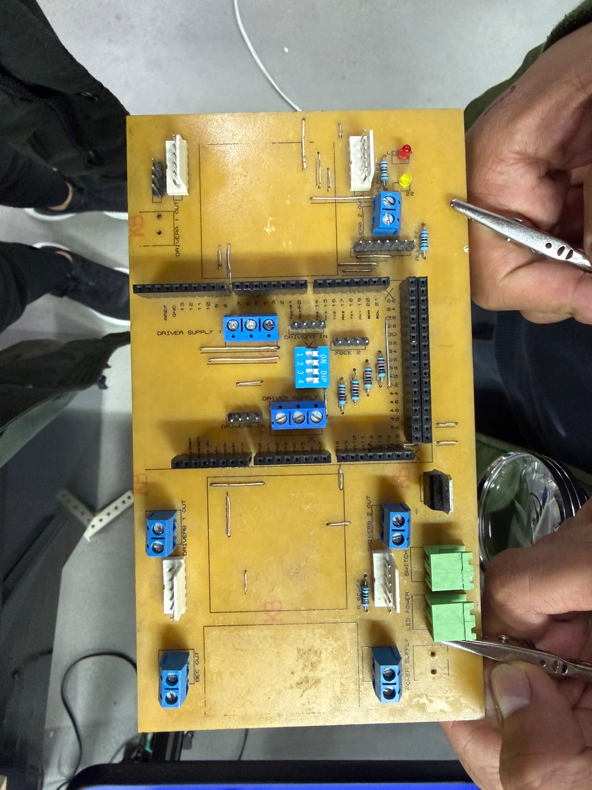
Building and wiring the custom control board.
I designed and assembled this custom PCB as the central integration board for the robot's electronics, and these two images show its two faces. In the first I'm checking the copper trace side — the milled routing that carries all the power and signal connections, with the soldered joints and a couple of jumper wires I added to bridge nets — probing it with test clips to verify continuity before powering it up. This testing step mattered because my earlier board was short-circuiting: traces left too close together were bridging and shorting the power and signal lines, so I had to remake the board, correcting the trace spacing and isolation in the design and re-milling it to get a clean, reliable layout. In the second image I'm populating the corrected component side, where I laid the design out around the microcontroller, which seats into the long black header rows so the board distributes every pin to the rest of the system. The white connectors are the outputs for the four motor drivers (with dedicated driver supply and input terminals), the green components are the switches, and I also placed the blue screw terminals for power in/out, a DIP switch bank for mode selection, an XBee header for wireless, the resistors, and the red and yellow status LEDs from my firmware. Working with tweezers and a fine tip, I soldered each part into its labeled position — assembling the single control hub that ties together power distribution, the four-motor drive, sensing, signalling, and configuration for the assistant, this time without the shorting problems of the first version.
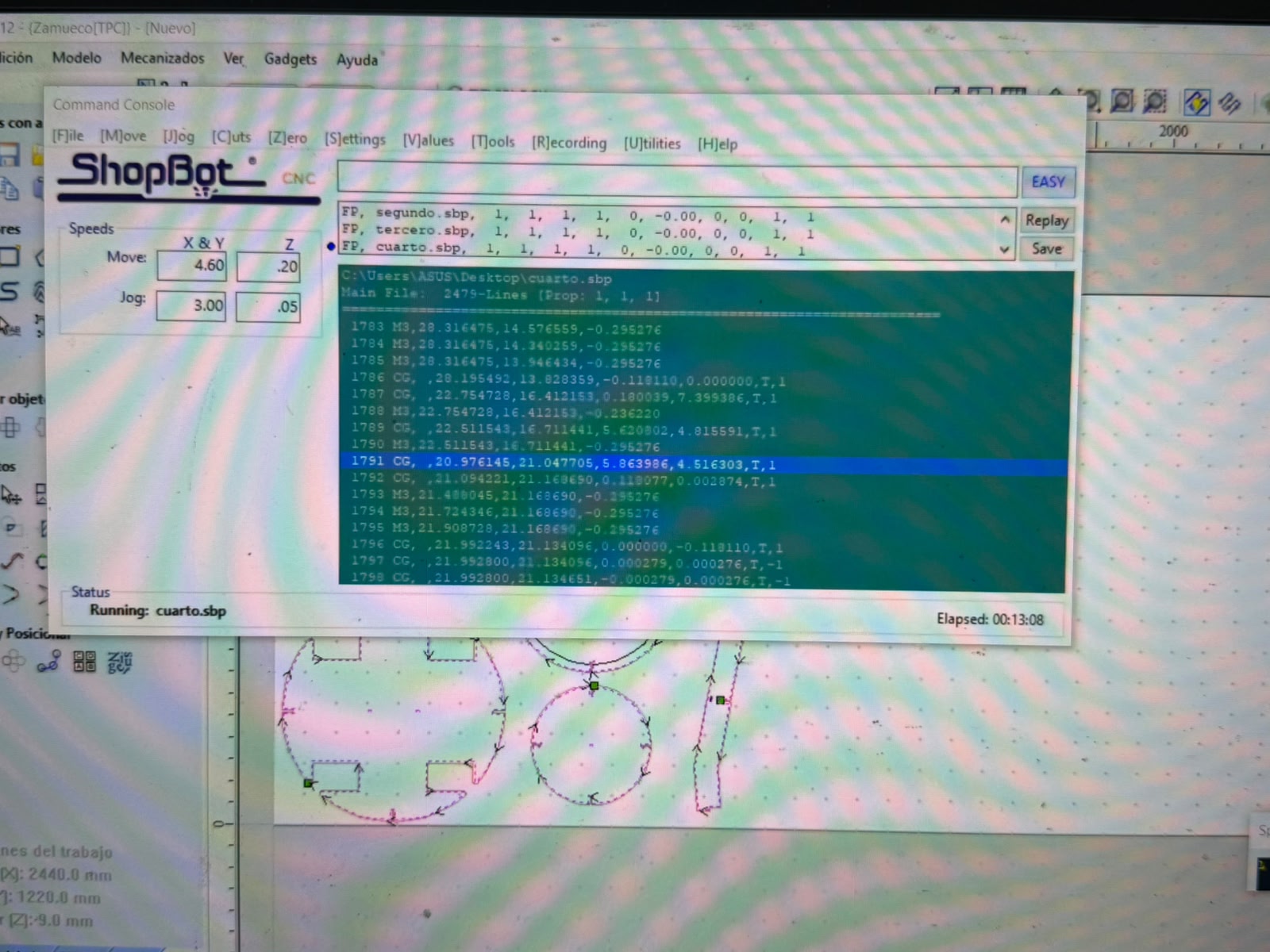
CNC routing of the plywood structural parts
This is the ShopBot CNC control software running the toolpath that cuts the robot's plywood components. The Command Console is actively executing the part file cuarto.sbp (status reads Running: cuarto.sbp, elapsed 00:13:08), one of a sequence of files (segundo.sbp, tercero.sbp, cuarto.sbp) corresponding to successive cut jobs. The main file holds 2,479 lines of G-code-style commands, and the scrolling list shows the machine working through them line by line — M3 moves positioning the cutter and CG commands tracing the circular/arc segments — each with its X, Y, Z coordinates and feed parameters. The Speeds panel sets the cutting and jog rates for the X/Y and Z axes, and the job dimensions at lower left (2440 × 1220 mm sheet, Z −9.0 mm) confirm a standard full plywood sheet with the cut depth matching the board thickness.
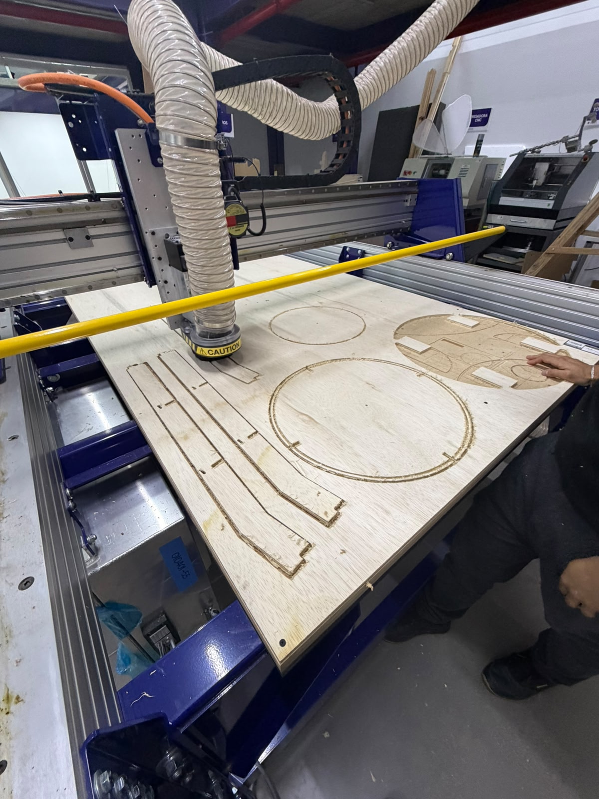
Wood Integration
These CNC-cut panels form the secondary structure that mounts onto the steel base frame, and the precision of the routing is what makes that integration possible. Because the parts are cut from the same digital model that defines the frame's geometry, their mounting holes, slots, and edge profiles can be dimensioned to align directly with the frame's members and fixing points — so the plywood decks and body sections drop onto the welded structure and bolt up without rework. The rounded outlines and internal cutouts seen in the preview correspond to the platforms and shell that close over the chassis: they create the flat mounting surfaces for the electronics bay, the Raspberry Pi, the motor driver, and the wiring, while also forming the visible body of the assistant. In this way the steel frame provides the rigid, load-bearing skeleton and the CNC-routed plywood provides the lightweight, accurately fitted enclosure and mounting decks built on top of it — the two structural layers referenced to a common geometry so they assemble together cleanly.
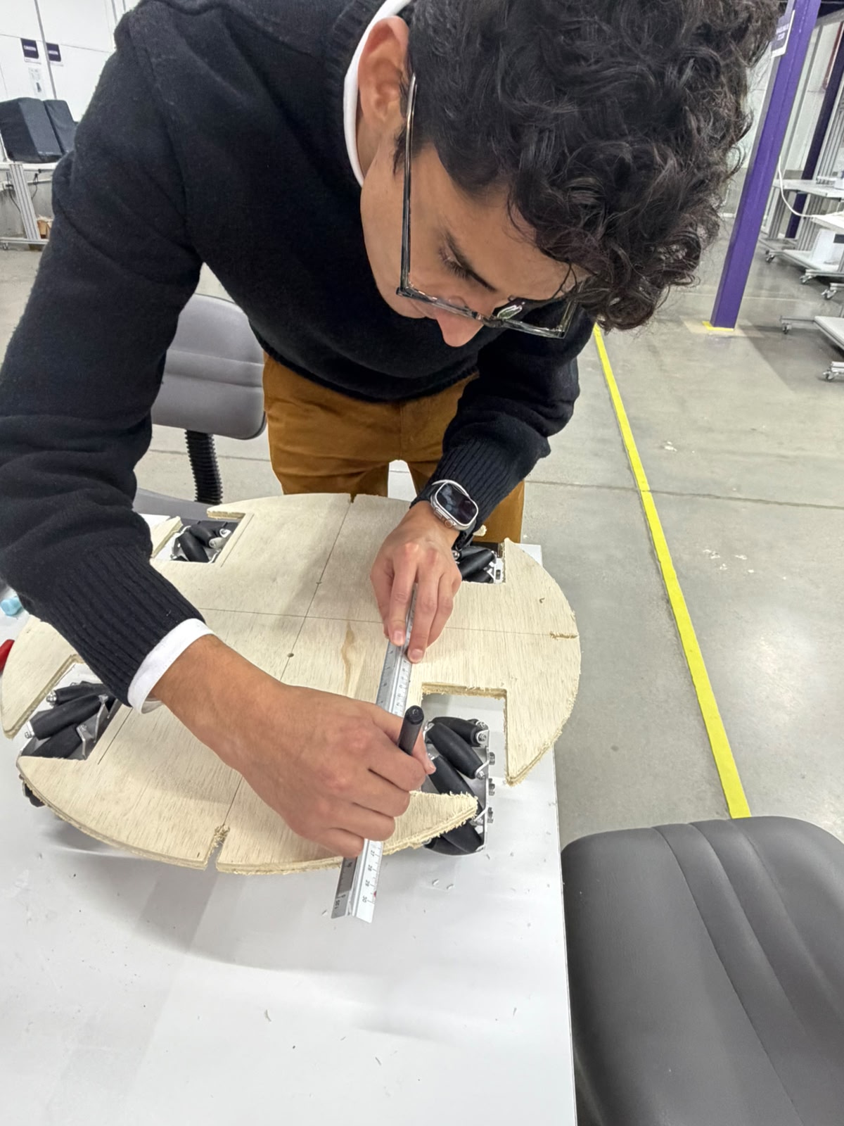
Wood Integration
In this step the CNC-cut circular plywood platform — the secondary structure that mounts onto the steel frame — is being measured and marked by hand to lay out reference lines and component positions. Using a steel rule as a straightedge and a marker, I´m drawing precise guidelines across the disc, establishing the center axes and the locations where the upper subsystems, fasteners, or section joints will be placed. The platform already shows its defining features from the routing stage: a circular outline with corner cutouts that clear the four mecanum wheels and a seam splitting the disc into segments for assembly and access. This manual layout complements the digital fabrication — the panel is cut automatically for accuracy, then marked on the bench to register the exact mounting points and alignment references needed to integrate the deck cleanly with the wheels and the base frame beneath it.
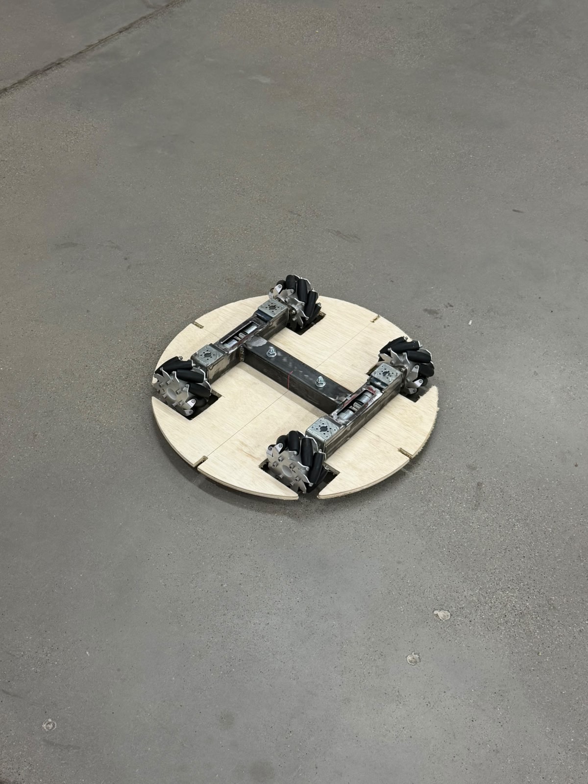
Integrated drive base - steel frame and plywood deck assembled.
This shows the two structural layers fully integrated: the welded steel H-frame (primary load-bearing structure) mounted beneath the CNC-cut circular plywood deck (secondary structure), with the four mecanum wheels seated at the perimeter — the finished rolling base of the assistant, resting on its own wheels. The steel frame carries the gearmotors and wheels in the symmetric, coplanar layout required for omnidirectional motion, while the plywood deck — routed to its circular profile with four corner cutouts that clear the wheels and split into segments for access — is bolted down flush as the mounting platform. Together they form a single, accurately fitted chassis in which the steel skeleton resolves load, balance, and wheel geometry, and the plywood deck provides the flat, ready surface onto which the electronics bay, compartments, and upper body will be built.
Electronics integration onto the drive base.
This top-down view shows the locomotion electronics mounted and wired onto the assembled chassis — the steel H-frame and circular plywood deck with the four mecanum wheels at the corners. The custom copper-clad control board sits at the center carrying the Arduino-class microcontroller, status LEDs, and terminal blocks, flanked by the red MOSFET/H-bridge motor drivers and a step-down converter that feed the four gearmotors. Each motor's power leads and its quadrature encoder ribbon run inward to the board and drivers, distributing drive commands and returning encoder feedback for closed-loop PID control, while the blue USB cable links to the perception side and the battery leads enter from the upper right. This is the stage where the mechanical base, drive electronics, control board, and power distribution are all mounted on the deck and interconnected — turning the rolling chassis into a functional, command-ready drive system, with deck space left for the Raspberry Pi, sensing, and upper body still to come.
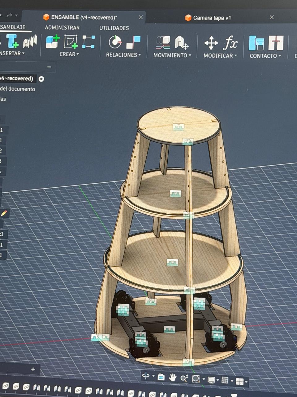
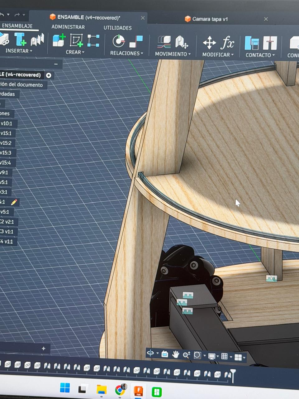
Parametric design of the body structure in Fusion 360.
The assistant's tiered body was developed as a parametric 3D assembly in Autodesk Fusion 360 before any material was cut, making the CAD model the central reference from which the entire physical build is derived. The structure is modeled as a stack of circular decks of decreasing diameter, separated and held by curved vertical ribs that rise from the drive base and define the robot's tapered silhouette. Each deck, rib, and frame element is modeled as an individual component and constrained to the others through assembly joints and relations, so the whole tower is built around a single coherent geometry rather than improvised part by part. Working parametrically also allows the design to be iterated through successive versions, refining proportions, clearances, and mounting positions while keeping every part dimensionally linked. This digital-first approach is what guarantees that the fabrication chain holds together. The same model that defines the form also generates the flat part profiles exported as ShopBot CNC toolpaths, fixes the deck diameters and rib geometry that establish the common datum for stacking, and locates the mounting points for subsystems such as the signalling LEDs and the electronics. By verifying fit, alignment, and dimensions in software before cutting, the design ensures that the routed plywood parts assemble cleanly with one another and integrate accurately onto the steel frame and drive base. In effect, the Fusion 360 assembly is where the assistant's body is engineered and validated, and the workshop stages simply materialize that validated geometry through digital fabrication.
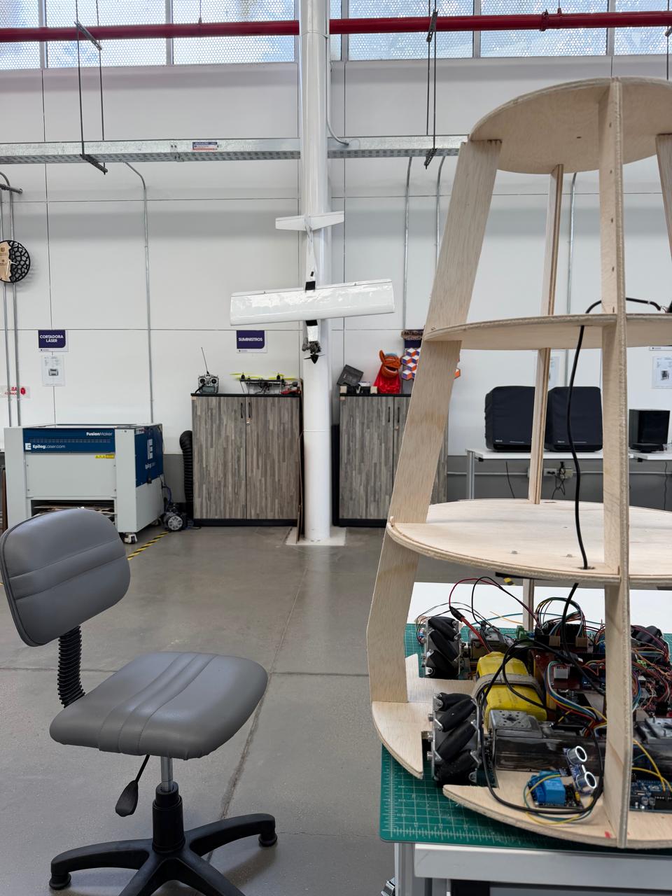
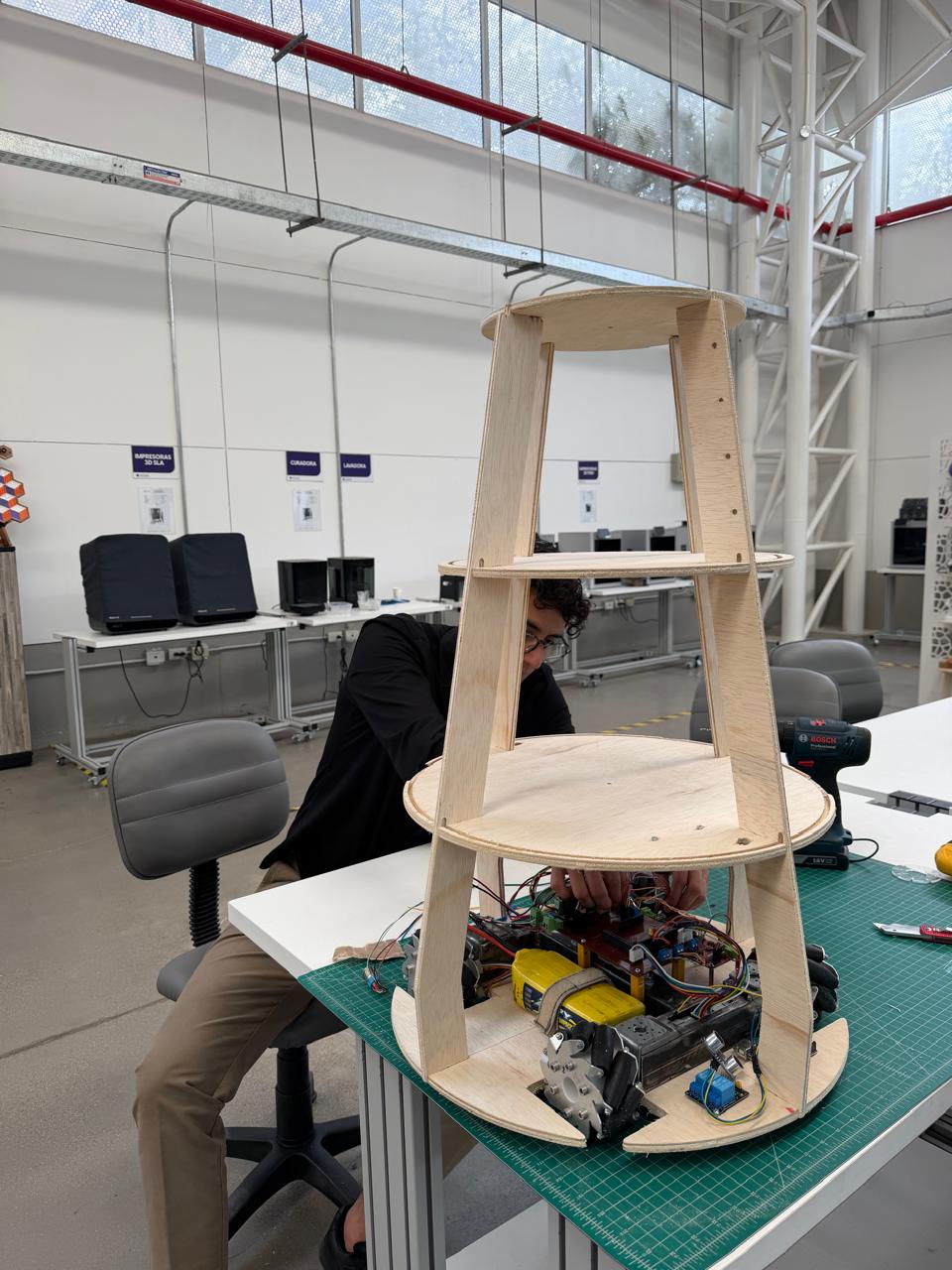
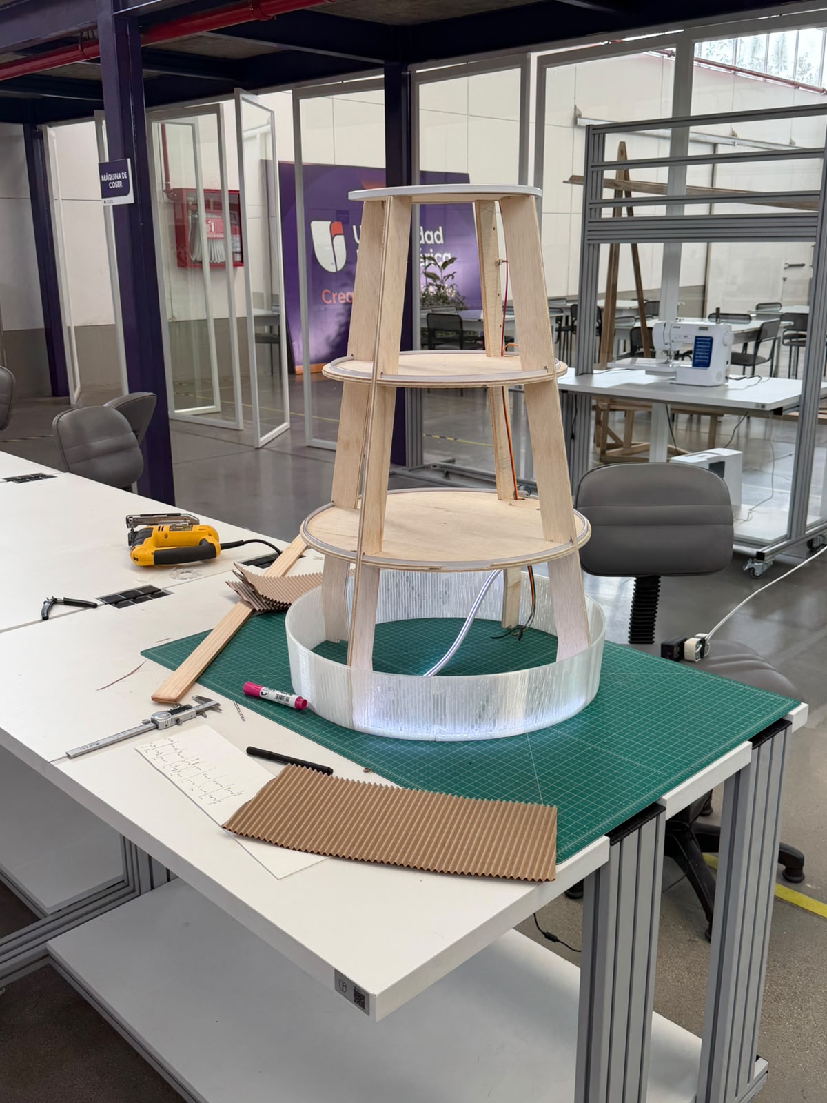
Vertical body structure integrated to driven base.
The body integrates with the chassis through the layered-deck logic established earlier: the lowest CNC-cut deck is the same platform bolted to the steel frame, and each successive level is referenced to it by the vertical ribs, so the whole tower rises from a common geometric datum. This tiered arrangement does the structural and functional work of the body at once — the bottom level houses the drive and power electronics close to the floor for a low center of gravity and stability, the curved ribs provide the vertical spine and define the tapered silhouette while leaving the sides open for wiring access, cooling, and sensor placement, and the upper decks create dedicated platforms for the higher subsystems still to be added (the Raspberry Pi, the cargo/courier compartments, the signalling top). In effect, the plywood superstructure transforms the flat rolling base into the full three-dimensional volume of the assistant, organizing the subsystems by level while keeping everything mounted to the single accurately-fitted structure built up from the steel frame.
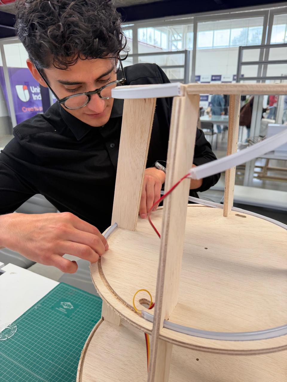
LED signalling system into the body structure.
At this stage I'm fitting the addressable LED strip lighting around the plywood body of the assistant, routing and seating the flexible strip along the circular edges of the tiered decks. Working by hand on the assembled superstructure, I press the LED strip into place along the rim of a deck while feeding the red and yellow power/signal wires through a pre-drilled hole in the platform, so they run down toward the control electronics below. I've already wrapped the white diffuser-channel strips along the upper deck edges and one of the vertical ribs, so the lighting follows the contours of the body rather than sitting on it as a separate fixture.
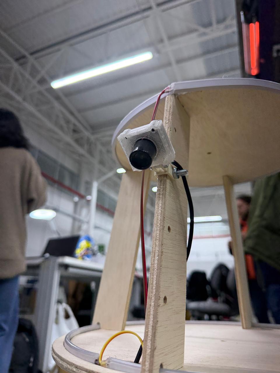
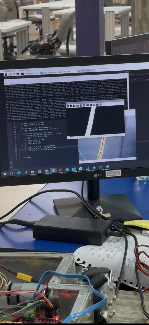
Integrating and testing the vision system.
In this step I brought the camera-based perception subsystem online and validated it in real time. I mounted the camera onto one of the vertical ribs of the body using a 3D-printed bracket bolted to the plywood, so the lens sits at the right height and angle, and routed its ribbon and power leads down along the rib toward the electronics below. I enabled and drove the camera through the Raspberry Pi — the same onboard computer that integrates all the operational logic — so the Pi captures the video stream and runs the image processing on board. To test it, I worked over a remote desktop session into the Pi (through RealVNC) and ran the line-detection routine on the camera feed. I checked exactly what the vision system was seeing — the raw camera image of the floor, a processed/masked view isolating the guide line, and the detected line overlaid with tracking points — and worked in the control code where the robot's mode logic lives, switching between states like STOP, MANUAL, and AUTO_LINE and computing the steering command from the line-detection outputs (line confidence, lateral error, and angle error) that feed into the drive system, with the chassis powered up beside me for the test. In doing so I enabled the webcam through the Raspberry Pi, confirmed it was capturing and processing the image correctly, and tested the line-following logic end to end — closing the loop between the perception subsystem (camera + Pi vision processing) and the locomotion subsystem (microcontroller + motor drivers), which is the core of the assistant's autonomous navigation.
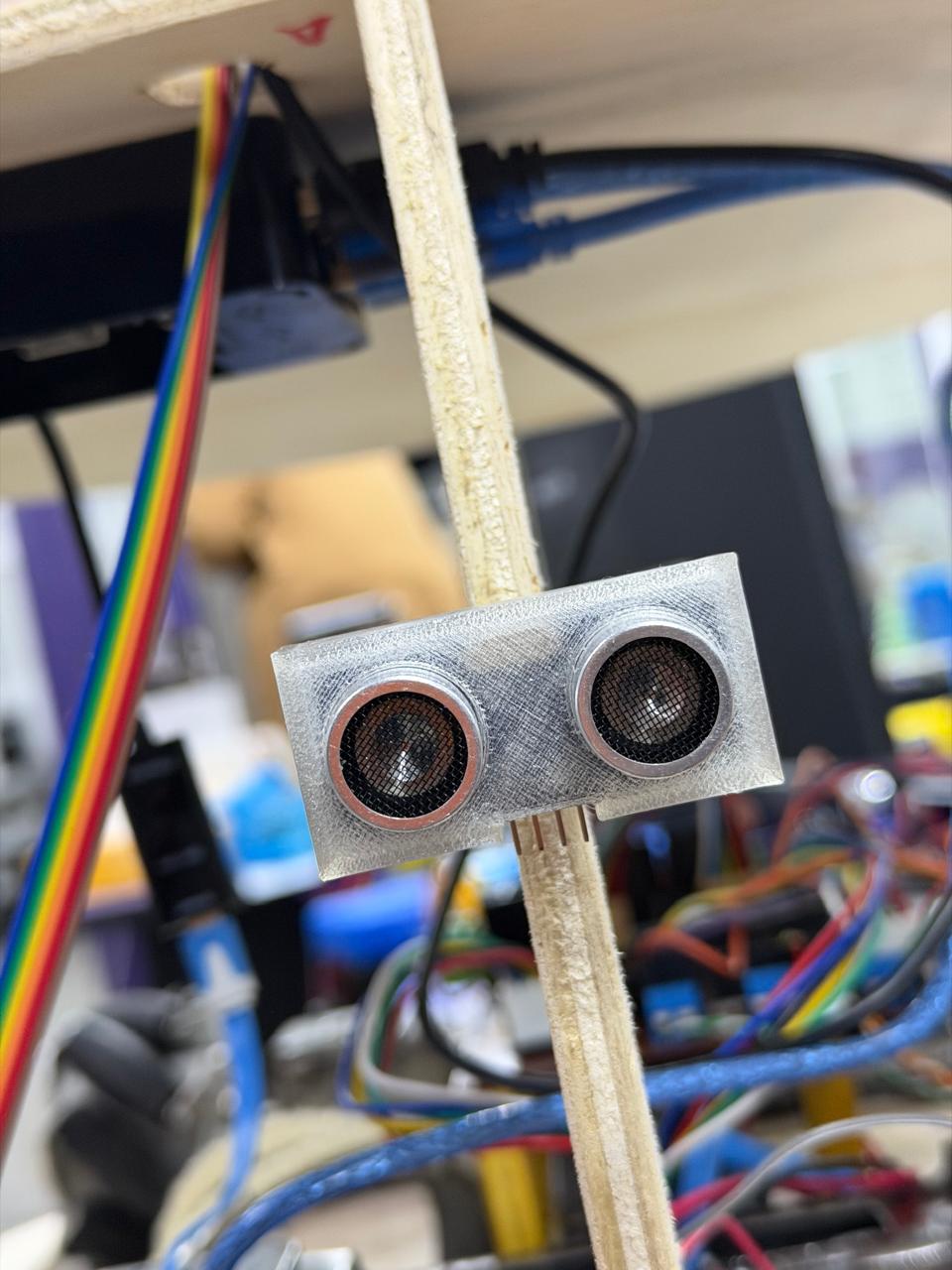
Ultrasonic proximity-sensing subsystem.
This is the HC-SR04 ultrasonic sensor mounted onto the assistant's body as the front-facing obstacle-detection input. The sensor is held in a 3D-printed bracket fixed to one of the plywood vertical ribs, positioning its two transducers — the T (transmitter) and R (receiver) metal-mesh cylinders — facing outward at the front of the robot so they have a clear line of sight ahead. Its four pins (Vcc, Trig, Echo, Gnd) are connected through the rainbow ribbon cable, which routes down along the structure to the control electronics on the lower deck, where the microcontroller and drivers sit. Functionally, this subsystem measures distance by time-of-flight: the controller pulses the Trig pin, the T transducer emits an ultrasonic burst, the R transducer picks up the echo reflected from any object ahead, and the sensor returns a pulse on Echo whose width is proportional to the round-trip time, from which the distance is computed. Mounted here at the front of the integrated body — alongside the camera, LEDs, drive electronics, and the wheels visible below — it gives the assistant its primary proximity sense, letting it detect objects in its path, evade obstacles, and brake when something comes within its safety threshold, complementing the camera-based navigation as part of the robot's perception layer.
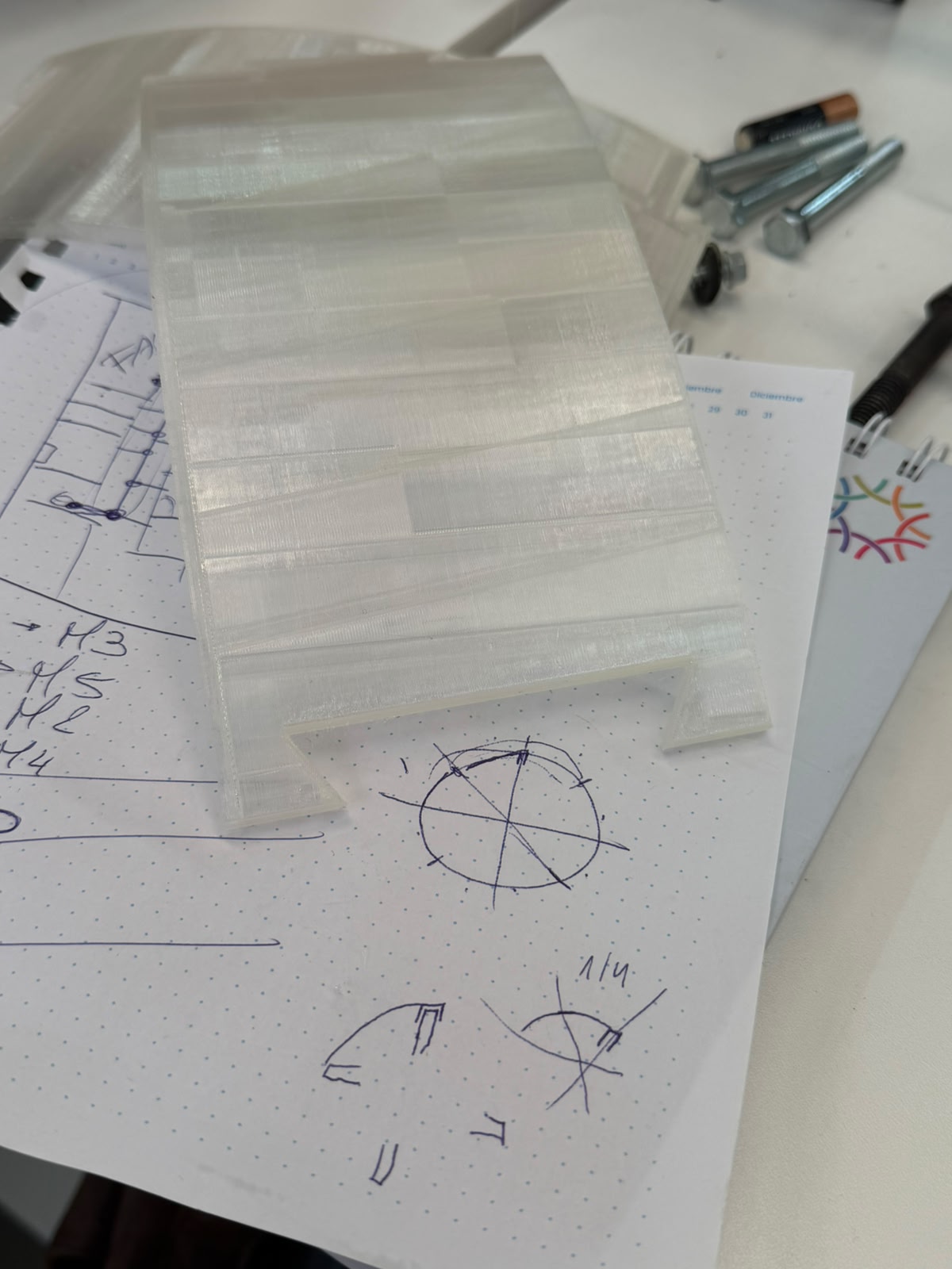
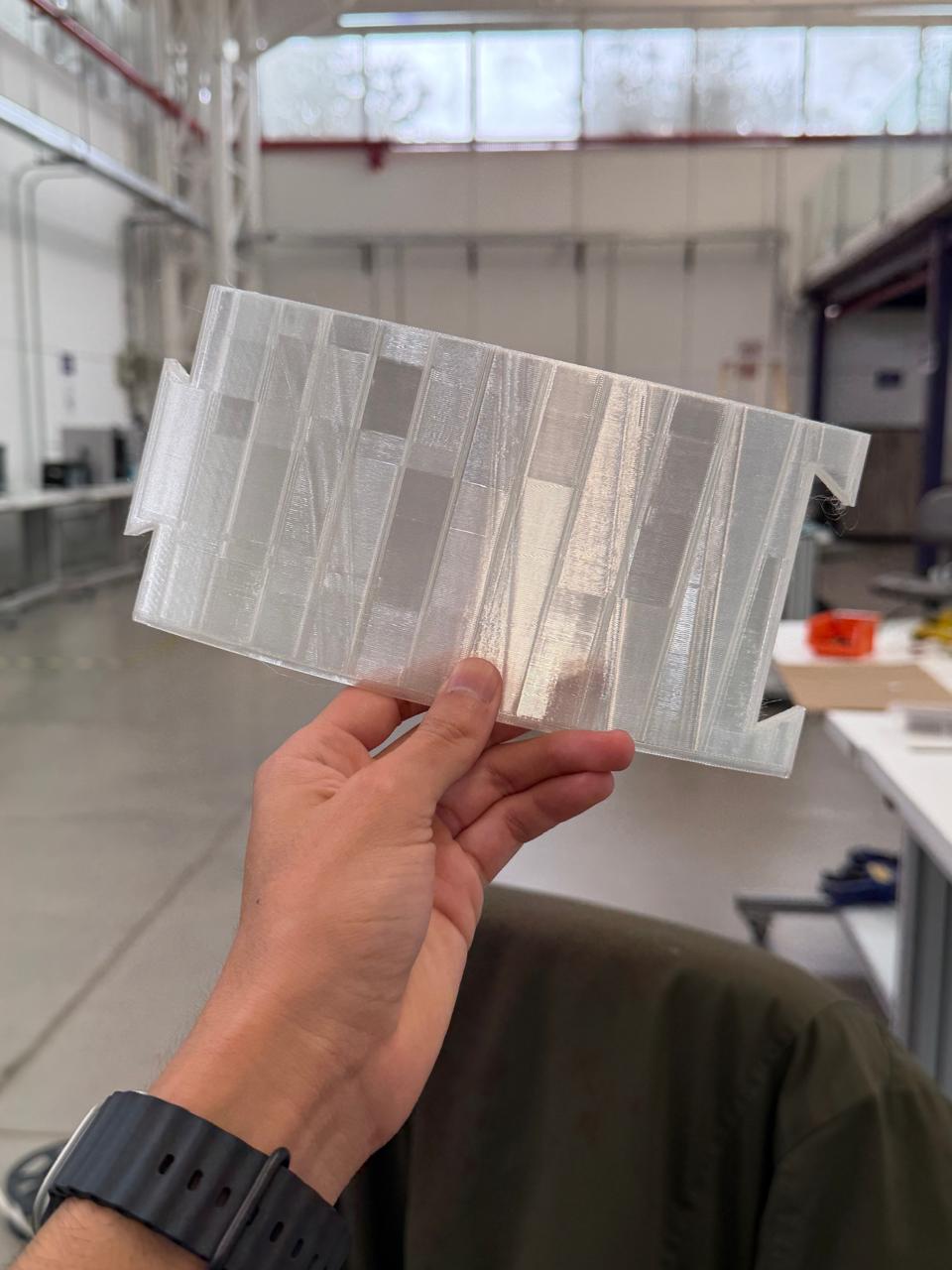
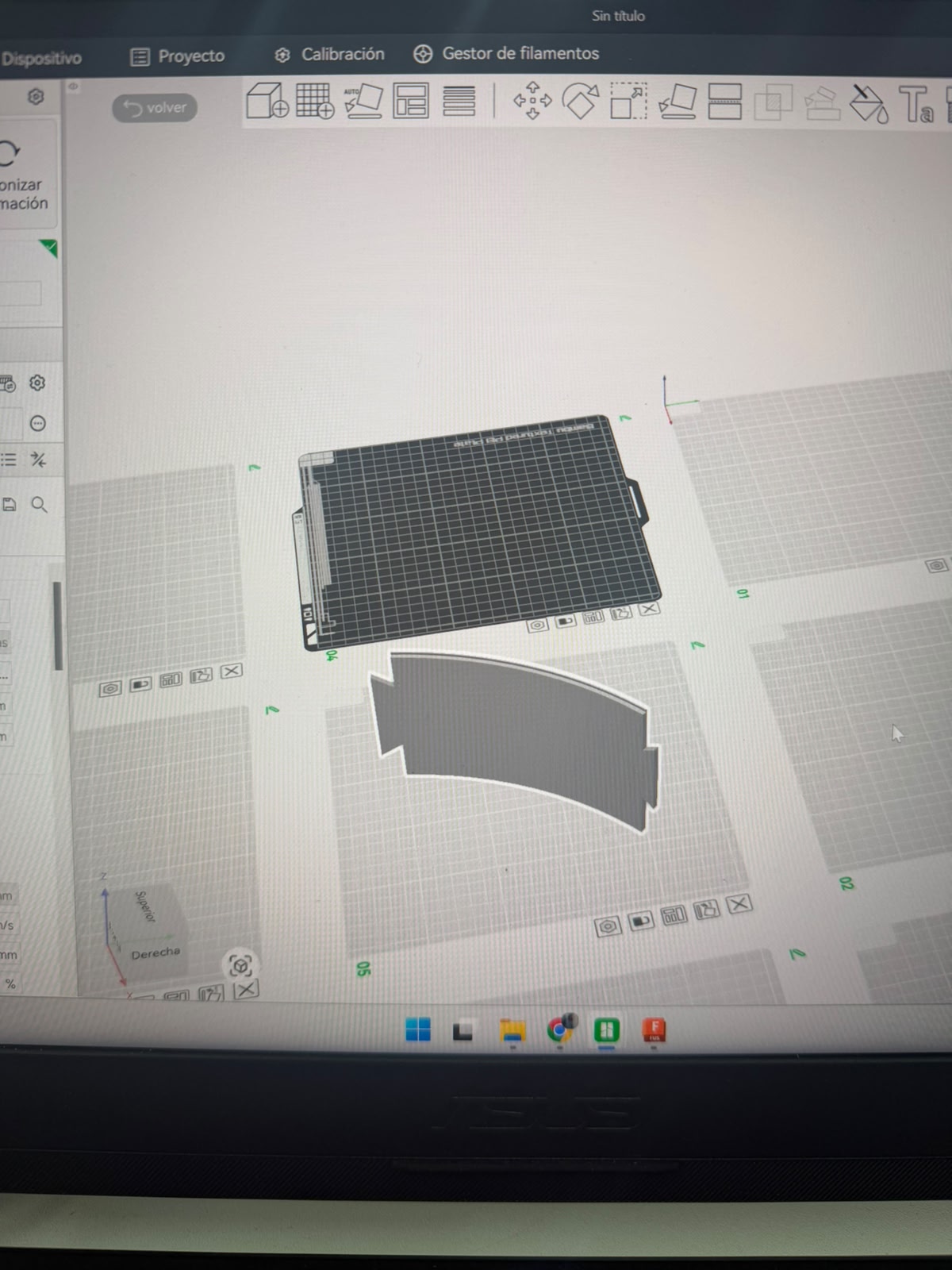
3D-printing the chassis parts — design and infill exploration.
At this stage I'm modeling the printed components in Autodesk Fusion 360: the viewport shows the base shell — the circular ring/collar part that wraps around and covers the power and control systems at the bottom of the robot - In the second image I'm holding one of the printed results up to the light — a translucent part printed in clear filament — and you can clearly see the internal structure through the walls. That's exactly what I've been studying: the different infill and wall patterns and how they show through and affect the finish. Printing in a transparent material makes the layer lines, the rectilinear infill grid, and the varying density regions visible, so I can judge how each pattern looks and feels on the surface, how light passes through it (useful since the body also carries the LED signalling), and how print quality and strength trade off. By exploring these fill patterns I'm dialing in the print settings — infill type, density, wall thickness — to get the surface finish and translucency I want for the base shell and the other final chassis parts before committing to the full prints.
Final Assembly
Here the first PLA-printed component — the base shell — is mounted in place at the bottom of the assistant's tiered plywood body, wrapping around the lowest deck where the power and control electronics live. Printed in clear filament, this ring forms the enclosure that covers and protects those systems while closing the base of the robot, and the LED strip sitting just inside it is already visible through the translucent wall. On the bench around it are the rest of the parts and tools mid-process — offcuts of plywood, the corrugated kraft paper samples, the caliper, markers, and notes — as I work through the finishing of the body. The intention behind the clear filament is to let the shell act as a diffuser rather than a solid opaque cover: because the body carries the LED signalling system, a translucent enclosure lets that light glow softly and evenly through the surface, turning the shell itself into part of the "how it talks" language of light rather than hiding the LEDs behind a wall. This is also why I tightened the infill spacing earlier — a finer, denser pattern diffuses the light more uniformly across the printed surface. For the final finish I'm considering wrapping or laminating the shell with sketch/tracing paper. The idea is to give the assistant a warmer, softer, paper-like skin — a matte translucent surface that still passes the LED glow but reads as light, handmade, and approachable rather than plastic. It would unify the look of the printed shell with the natural plywood structure, soften the visual weight of the body, and reinforce the human-centered, friendly character I want the assistant to project, while the corrugated paper samples on the table are part of testing how those paper textures look and feel against the form.
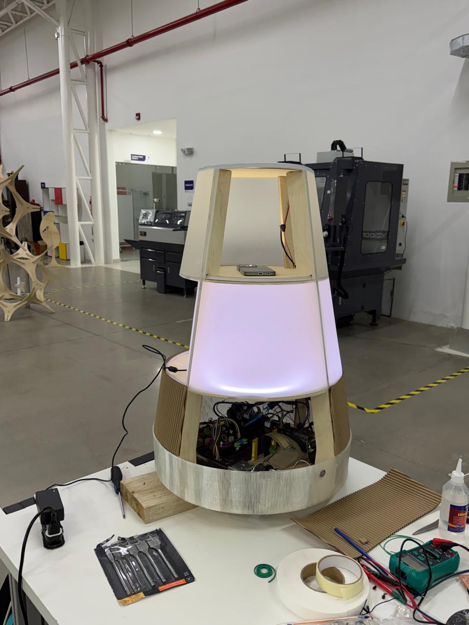
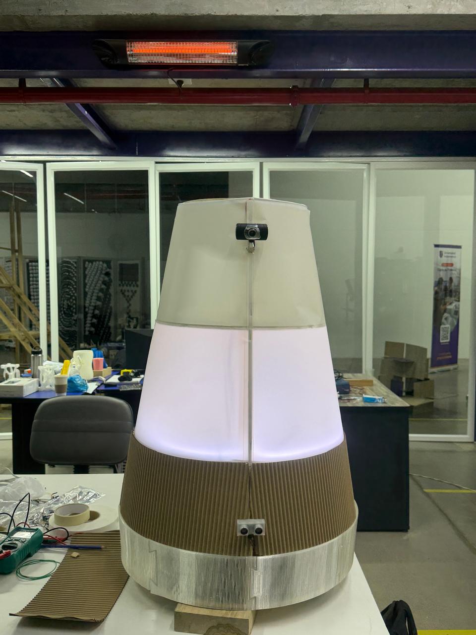
3D-printing the chassis parts — design and infill exploration.
These two images show the Automated Assistant brought together as a complete, working object, with the body now skinned, the lighting installed, and all the subsystems housed inside the tiered structure. The tapering cylindrical silhouette designed in Fusion 360 and built up from the steel frame and plywood decks is now closed in, and for the first time the robot reads as a single, intentional product rather than an open skeleton of parts. The finish combines the three material languages I'd been testing. The PLA-printed shell forms the lower enclosure that wraps and protects the power and control electronics at the base, the sketch/tracing paper skins the mid and upper body as a soft, matte, translucent surface, and the corrugated cardboard wraps the lower band as a warm, tactile texture — together giving the assistant the light, handmade, paper-like feel I was aiming for instead of a hard plastic look. The natural plywood structure and the kraft tones keep it visually warm and approachable, consistent with the human-centered character of the project. With the LED signalling system installed inside, the translucent paper-and-PLA midsection now glows from within — visible here as the soft lilac/white light diffusing evenly across the whole surface, exactly the "language of light" the design was built around. The first image shows the body still partly open at the base, with the electronics bay and wiring visible inside before final closing, while the second shows the assistant fully assembled and lit, with the camera mounted at the front of the upper section as its "face." The result is the integrated assistant: the mechanical drive base, the control and power electronics, the perception and signalling subsystems, and the finished translucent skin all unified into the glowing, approachable, screen-free robot the project set out to create.
1The body
A 70 cm cylinder of stacked sections — drive base, cargo compartments, an electronics-and-power bay, and a signalling top — each with its own job, plus access panels and tidy placement of compartments, lights, and sensors.
2How it moves
An omnidirectional drive on four omni wheels for smooth, holonomic motion: drive deck, motor and wheel mounting, and the geometry that lets it glide and turn predictably along routes it remembers.
3The compartments
Secure, lockable cargo spaces at the heart of the courier role — sizing, dividers, latching, open/closed sensing, and the screen-free way you pick a destination.
4How it "talks"
Since it's screen-free and quiet, a whole language of light (colour, motion, status) and minimal sound that signals what it's doing — drawing attention, guiding, waiting, delivering, alerting. This is where the friendliness lives.
5How it behaves
The system that records, stores, and replays routes from memory, coordinates the drive with the sensors, and sequences its functions and cues — how it carries itself across a whole day.
6The electronics
The architecture that ties compute, motor control, power, sensing, and signalling into one reliable — and importantly modular — system, so future teams can add new functions without redesigning everything.
7Its identity
A name, a character, a presence — what turns a machine into a member of the campus and makes people want to say hi. This is what drives the whole goal of feeling natural rather than novel.
The ingredientsMaterials & components
1Compute & control
Raspberry Pi 3 (high-level, runs the webcam & vision), Arduino Mega (real-time), 2× motor drivers (BTS7960 / Cytron / Pololu VNH), level shifters, jumper sets, protoboard.
2Movement
4× omni wheels (100–150 mm), 4× geared DC motors with quadrature encoders, mounts and shaft couplers / hubs.
3Navigation & sensors
USB webcam (vision, on the Raspberry Pi 3), IR line / reflectance array, floor markers, ultrasonic ring (HC-SR04), IR proximity sensors, IMU (MPU-6050 / BNO055), bump switches.
4Power
LiFePO4 pack (12 V, ~7.5–20 Ah), BMS, 2× DC-DC buck converters, main switch, inline fuses, matched charger.
5Compartments
Solenoid / servo latches, reed / door sensors, momentary buttons or rotary selector (destination input), trays and dividers.
6Communication output
Addressable LEDs (WS2812B / NeoPixel), top status ring, DFPlayer Mini + small speaker (or piezo buzzer), microSD card.
7Chassis & structure
Aluminium base / drive-deck plate, 2020 / 2040 extrusion frame, shell panels (PETG / acrylic / 3D-printed — Fab Lab), fasteners, cable management, access panels.
8Tools & consumables
Connector kits (JST, XT60 / XT90, Dupont), heat-shrink, solder, thermal paste / heatsinks. Soldering station, multimeter, bench supply assumed in the lab.
9Software
Pi OS / firmware environment, Arduino IDE / PlatformIO, VS Code, motor / encoder libraries, optional ROS 2 — all open-source.
The numbersWhat it will cost
Estimated budget by category. These are planning figures, not quotes — replace Low / High with real local supplier prices. Custom structure and shell parts are fabricated in the Fab Lab; only filament / sheet cost is counted.
| # | Category | Low (USD) | High (USD) |
|---|---|---|---|
| 1 | Compute and control | $180 | $320 |
| 2 | Movement (omni drive) | $220 | $450 |
| 3 | Navigation & sensors | $80 | $180 |
| 4 | Power system | $200 | $320 |
| 5 | Compartments | $80 | $160 |
| 6 | Communication output | $50 | $110 |
| 7 | Chassis & structure | $120 | $280 |
| 8 | Build tools & consumables | $60 | $140 |
| 9 | Software / non-physical | $0 | $0 |
| TOTAL | $990 | $1,960 | |
| Contingency (15%) — import markup + replacement parts | $149 | $294 | |
| PLANNING TOTAL (incl. contingency) | $1,139 | $2,254 |
Hands-onWhat gets made, not bought
One of the best things about this project is how much of the assistant is made rather than bought. The purchased components — motors, controllers, sensors, batteries — are the organs, but the body that houses and connects them is designed and fabricated in-house, most of it right in the Fab Lab. That's what makes it a genuine community build, not an assembly of off-the-shelf parts.
🦴Structural skeleton
The internal frame everything mounts to — aluminium cut and assembled in the lab, with fabricated plates defining each level of the cylinder.
🛢️Sectional body
The shell built as stacked sections rather than bought as a casing: laser-cut ribs and panels, 3D-printed rings and connectors, and segmented skin — each section made, tested, and revised on its own.
⚙️Drive deck
The base plate carrying the wheels and motors, fabricated to hold the precise holonomic geometry, with printed or machined mounts and hubs.
📦Compartment system
Lockable cargo boxes, doors, dividers, and trays sized for real cargo, with mounts for latches and door sensors built into the printed or cut parts.
🔩Mounts & housings
Sensor brackets, controller and battery trays, the LED-ring housing, button panels, the speaker mount, cable guides, and access panels — fast, cheap 3D-printed pieces.
💡Interface surfaces
The screen-free destination panel, the surfaces that carry notices and QR cards, and the diffusers that shape the LED light into a clear, friendly language.
🔗Integrated systems
Wiring and power distribution, the compute-and-control architecture, and the route-and-behaviour logic written specifically for this assistant — built here, not shipped in a box.
The howProcesses I'll use
The build draws on a focused set of digital-fabrication processes from Fab Academy — the ones genuinely needed to design, build, and bring the assistant to life.
🧊 CAD
Modelling the whole assistant as one assembly before any material is cut — proportions, stacked sections, component clearances — and generating every file downstream.
✂️ Computer-controlled cutting
Laser-cutting flat structural and surface parts: level plates, ribs, press-fit joints, skin panels, and light diffusers — fast and cheap to iterate.
🖨️ 3D printing
The bespoke 3D parts: structural rings and connectors, motor mounts and wheel hubs, and the many small housings that adapt bought parts to the custom body.
🛠️ CNC machining
The larger load-bearing parts — chiefly the drive-deck base plate that holds the wheel geometry rigidly under the weight of the whole assistant plus cargo.
📟 Embedded programming
Firmware on the microcontroller: driving the four Mecanum wheels through inverse kinematics, reading encoders, polling sensors, and running the route record-and-playback logic. See the full deep-dive ↓
🎚️ Input devices
Encoders, line / marker sensors, ultrasonic and IR sensors, IMU, and door sensors — each placed to serve a specific function.
🔊 Output devices
Motors for movement, addressable LEDs and a status ring for state and intention, and a minimal-sound emitter — coordinated to stay legible to people nearby.
🔧 Mechanical design
The holonomic drive, the moving compartment mechanisms, and the logic that lets stacked sections combine into one stable, serviceable body.
🌐 Networking & comms
The internal link between the high-level controller (Raspberry Pi 3 — webcam, vision, routes, cues) and the real-time microcontroller (Arduino Mega — motion, sensing) — one coherent behaviour from two boards.
🕹️ Interface programming
The screen-free destination interface and the logic that turns capabilities into the light and sound cues people read.
🧩 System integration
The finale: fitting every subsystem inside one cylinder — power routing, weight balance, maintenance access, and resolving the conflicts that only show up once it's all together.
Embedded programming · deep-diveDriving the Mecanum wheels
One configuration rule first. Mecanum drive only works if the rollers form an “X” pattern on the underside of the chassis. Looking down from above, the top-facing rollers of the four wheels should point inward toward the centre, forming an X. Get one wheel mirrored and the robot will fight itself instead of strafing. The standard layout: front-left & rear-right are one roller handedness, front-right & rear-left are the mirror. This is the single most common Mecanum build mistake — worth checking before any code is written.
The components the firmware talks to
🧠Real-time controller
An Arduino Mega runs the motion loop: it receives a target velocity, solves the wheel speeds, and updates the motors hundreds of times a second. The Raspberry Pi 3 handles the webcam, vision, routes, and decisions; this board handles motion.
🔀Motor drivers ×4
One H-bridge channel per wheel (BTS7960 / Cytron / Pololu VNH). Each takes a direction pin and a PWM speed signal — four independent channels, because every wheel may spin at a different speed and direction at the same time.
⚙️Geared DC motors ×4
Each wheel is driven by its own motor. Speed and direction are commanded individually — the whole Mecanum trick depends on the four wheels not moving together.
🔄Quadrature encoders ×4
Mounted on each motor, they count shaft rotation so the firmware knows how far each wheel has actually turned. They are essential for repeatable routes and for closed-loop speed control.
🧭IMU (heading)
A 6/9-axis IMU (MPU-6050 / BNO055) measures the robot's actual heading, so the firmware can correct the small drift that Mecanum wheels are prone to and keep straight lines straight.
🛑Safety sensors
The ultrasonic / IR ring and bump switches feed the same loop, so the motion controller can slow or stop for people before the kinematics ever command a move.
The kinematics: turning intent into four wheel speeds
The robot is commanded with just three numbers — a body-velocity vector: vx (forward), vy (sideways / strafe), and ω (rotation). The job of inverse kinematics is to convert those three numbers into the four individual wheel speeds. For the standard Mecanum X-layout, each wheel speed is:
What matters in practice is the sign pattern — the +/− combination is what produces each motion. This table is the heart of the whole drive system:
| Motion | Front-L | Front-R | Rear-L | Rear-R |
|---|---|---|---|---|
| Forward | + | + | + | + |
| Reverse | − | − | − | − |
| Strafe right | + | − | − | + |
| Strafe left | − | + | + | − |
| Rotate CW | + | − | + | − |
| Rotate CCW | − | + | − | + |
| Diagonal ↗ | + | 0 | 0 | + |
The firmware, in code
In practice the equations above become one small function that the motion loop calls continuously. A trimmed version of the core looks like this:
// Body command -> four wheel PWM values (Mecanum X-config)
void driveMecanum(float vx, float vy, float w) {
  // 1. inverse kinematics: mix vx, vy, w into 4 wheel speeds
  float fl = vx - vy - w;
  float fr = vx + vy + w;
  float rl = vx + vy - w;
  float rr = vx - vy + w;

  // 2. normalise so no wheel exceeds max (keeps the path true)
  float m = max(max(abs(fl),abs(fr)), max(abs(rl),abs(rr)));
  if (m > 1.0) { fl/=m; fr/=m; rl/=m; rr/=m; }

  // 3. send each wheel its own direction + PWM speed
  setMotor(FL, fl);  setMotor(FR, fr);
  setMotor(RL, rl);  setMotor(RR, rr);
}

// One wheel: sign -> direction pin, magnitude -> PWM (0..255)
void setMotor(int wheel, float speed) {
  digitalWrite(dirPin[wheel], speed >= 0 ? FWD : REV);
  analogWrite(pwmPin[wheel], (int)(abs(speed) * 255));
}
The programming process, step by step
Bring up one motor
Wire a single motor + driver and confirm direction and PWM speed respond correctly. Map which physical wheel is FL / FR / RL / RR and lock down the pin assignments.
Verify the roller X-pattern
Before mixing anything, physically confirm the four wheels form the correct X. A quick "all wheels forward" test should drive straight; if it crabs sideways, a wheel is mirrored.
Read the encoders
Set up interrupt-driven quadrature counting for all four wheels. Confirm counts rise when a wheel rolls forward and fall in reverse — the basis for distance and closed-loop speed.
Implement inverse kinematics
Add the driveMecanum(vx, vy, w) mixing function and normalisation. Test each motion in isolation: forward, strafe, rotate, then diagonals.
Close the loop (PID)
Use the encoder feedback in a per-wheel PID controller so each wheel actually reaches its commanded speed under load — essential when the robot is carrying cargo.
Fuse the IMU for heading
Feed IMU heading into a correction term so straight lines stay straight and rotations land on target, compensating for Mecanum's natural slip.
Record & play back routes
Log the velocity commands (and encoder distances) over time to memory; replay them to repeat a memorised path through the park — the foundation of every route-based function.
Layer in safety
Gate the whole motion loop behind the obstacle sensors so any commanded velocity is scaled to zero when a person or object is detected — the kinematics never override safety.
Being honestQuestions still to answer
A good project names what it doesn't know yet. These are the open questions across the technical, human, and institutional sides — the things still to test, decide, or design.
🛞 Movement & navigation
Will the holonomic drive move reliably across real floors and thresholds? Is the memory-based route system repeatable over distance, or will drift need correction waypoints? How does it stop for people while still finishing its routes?
🛢️ Form & fabrication
Will the stacked cylinder stay rigid and balanced once loaded? Is the centre of gravity low enough to avoid tipping in turns? Can each section be made and revised independently within the Fab Lab's capacity?
🔋 Power & autonomy
How long can it run on a charge while doing its routes — and is that a useful working block? How and where does it recharge, and does that fit the campus day?
📦 Compartments & courier
Are the compartments sized for the cargo labs really move? Is screen-free destination-picking intuitive for a first-timer? Are contents secure enough that people will trust the assistant with them?
🤝 Friendliness & acceptance
Is the light-and-sound language clear without instructions? Will the community actually warm to it — or treat it as a novelty and ignore it? Does its presence in shared corridors feel natural or intrusive?
⭐ Real value
Which day-one functions are genuinely useful, and which only look good on paper? Does it measurably save time and trips? Is the platform truly open enough for future teams to extend?
🏛️ Viability
Are parts reliably available locally, and what are real lead times and costs? Is the budget enough once markups and test-time replacements are counted? Who maintains, charges, and owns it once it's running?
Conclusions
← Back to Main Page