Week 15, System Integration
Table of Contents
- Overview
- Resources
- Final Version
- 3D Design
- Assembling
- Files
Overview
This week, I created the body of my robot, which includes the place to put my PCB, the screwing holes for my servos etc.
Resources
- I used Fusion 360.
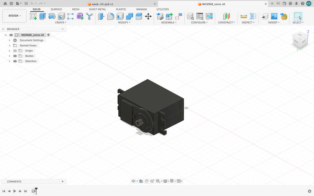
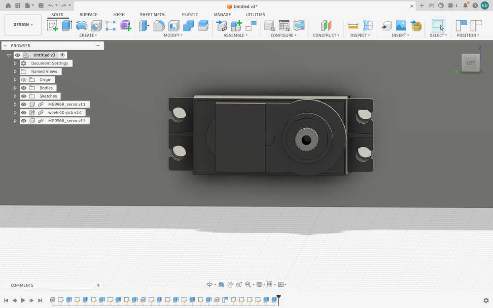
- Here is the 3D model of the servo I used.
Final Version
3D Design
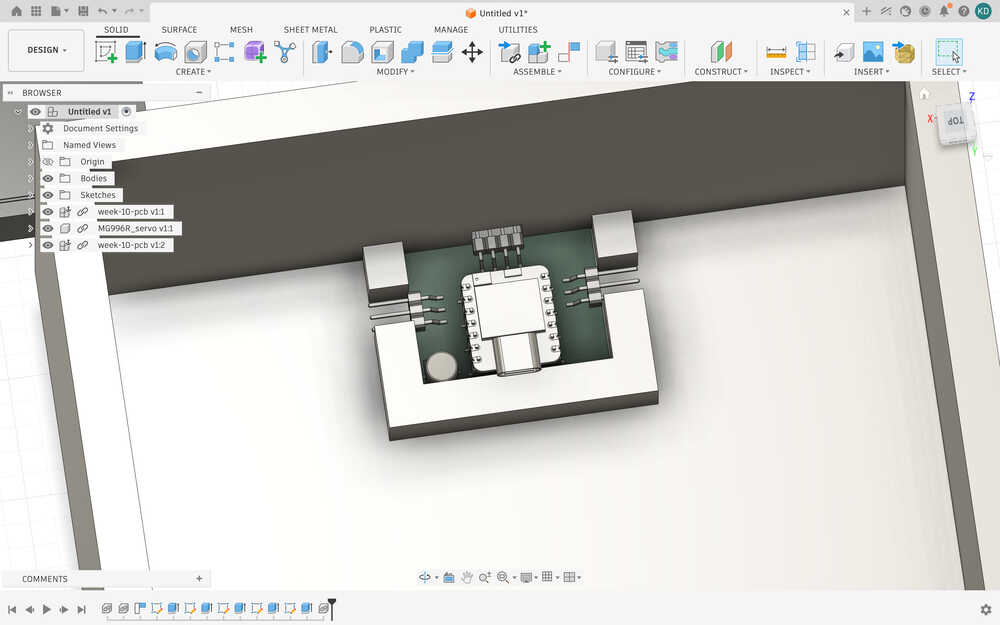
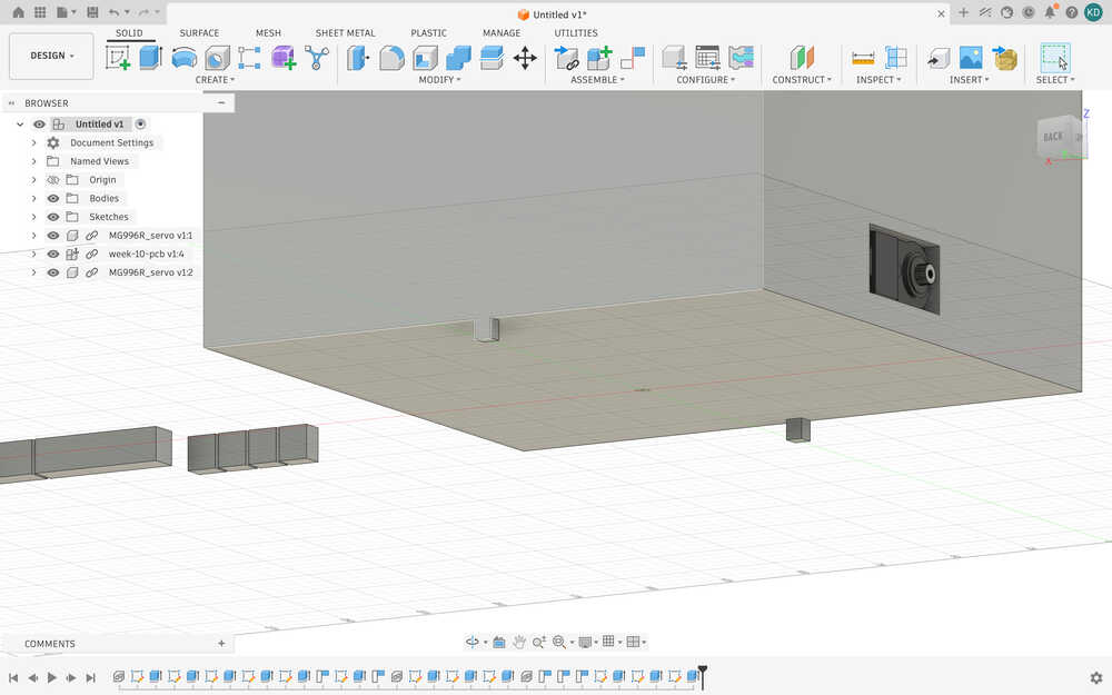
I started by importing my PCB's 3D view into Fusion 360.
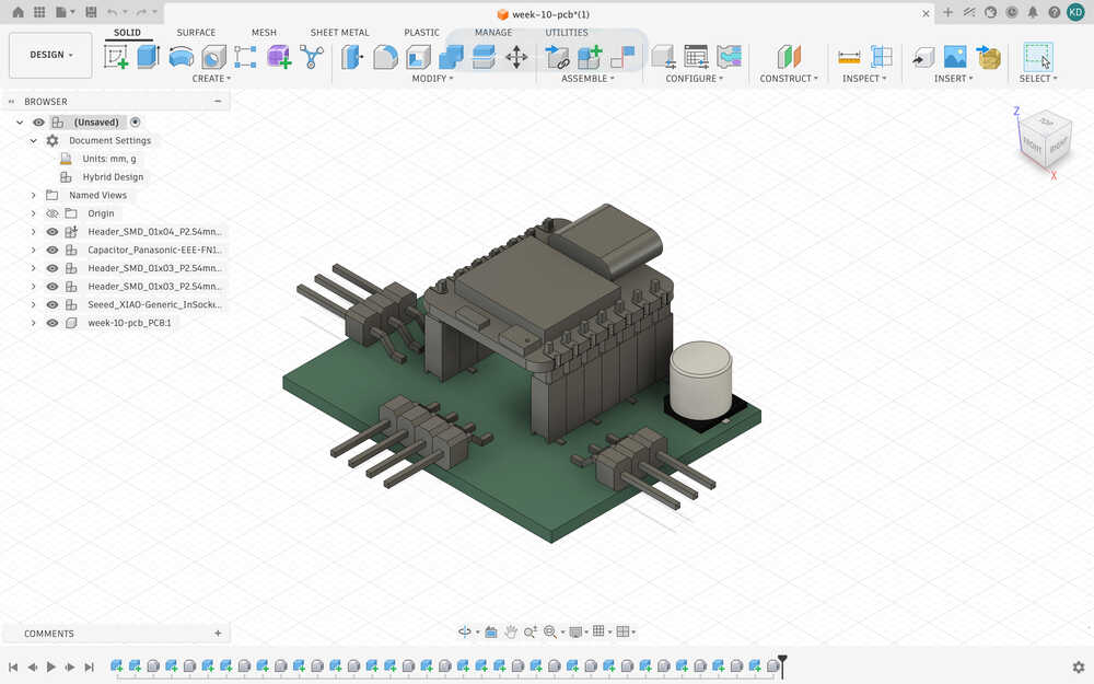
Then, I downloaded the 3D model of the servo I'll use from this link.
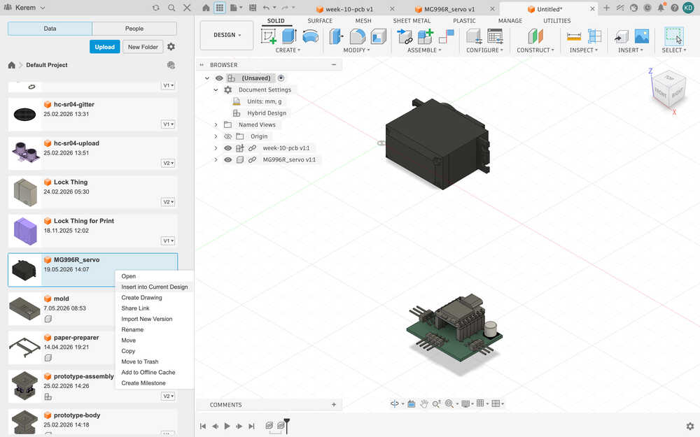
I inserted the two components into a new design I opened.
I created some parameters.
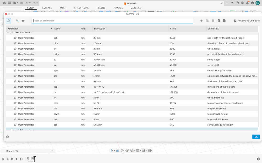
I extruded the bottom part by t (thickness) and gave it a height of wr-t (wheel radius - thickness).
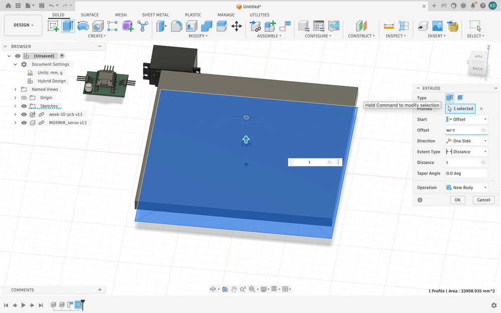
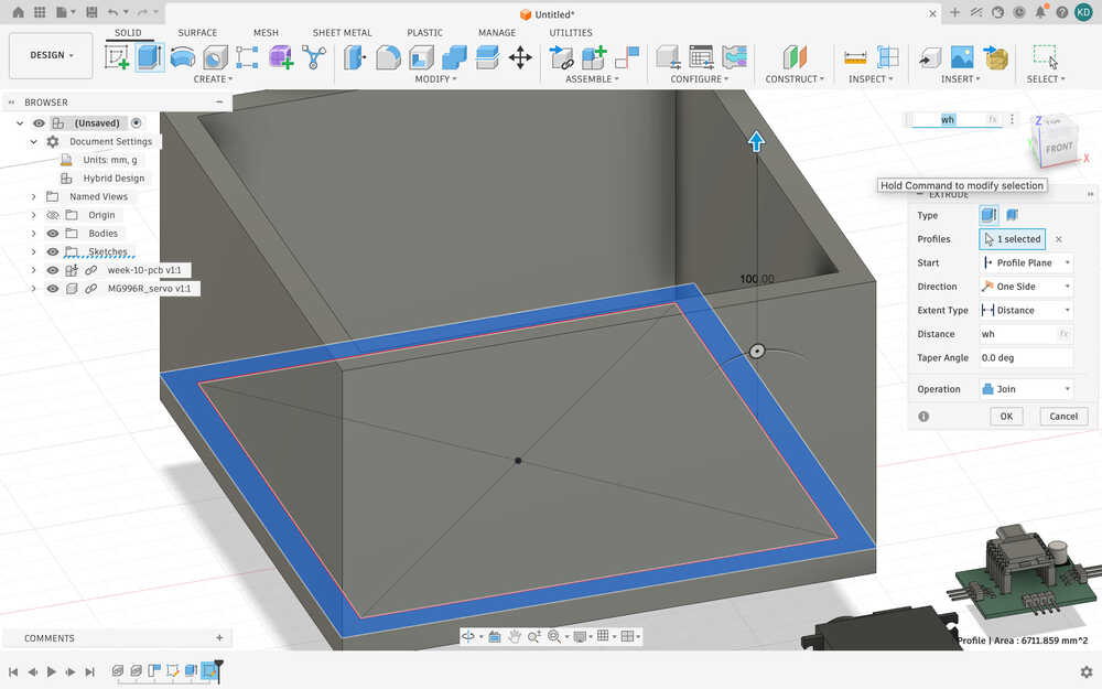
I created walls for the robot. The walls are a height of wh, a new parameter with a value of 100mm.
I created a new parameter named hh, hole height, which has a value of 8mm. It is for making creating access to the VL53L1X from the PCB.
I created a parameter named sh, which is the servo's height, and iwh, the inner wall height, equal to sh/2 (10mm). I also decided to just change hh to iwh. I also created the walls of where the PCB will be.
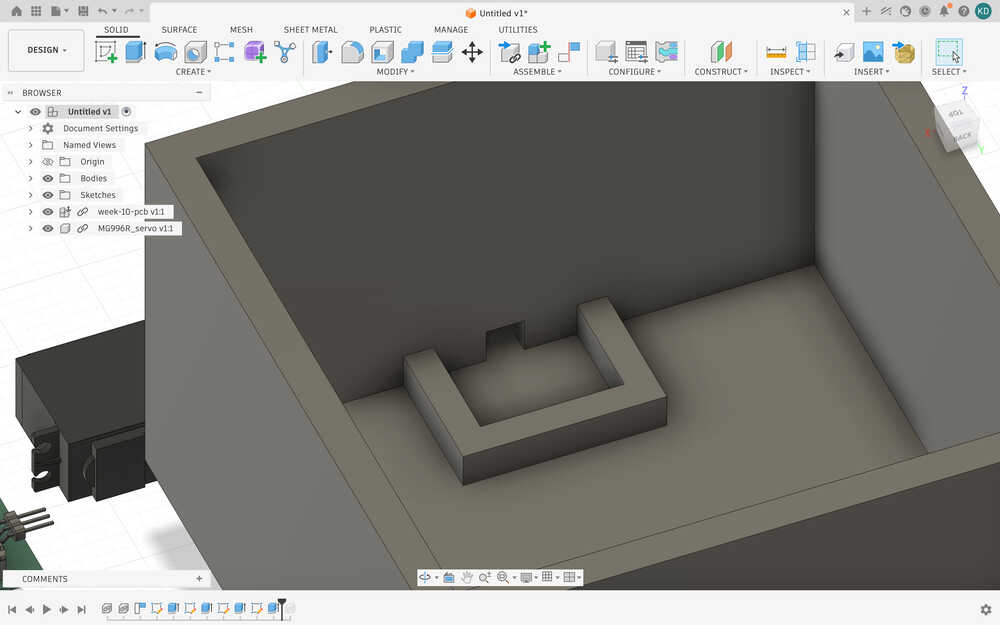
I created holes in the sides and put the PCB to its position.
I created the wall/hole part of one of the servos. I also created some things to fix the servos in place.
I finished the other one. I also created another parameter, sspw, which is the width of the shorter side part of the servos. You see, I realized that one of the side parts was shorter than the other.
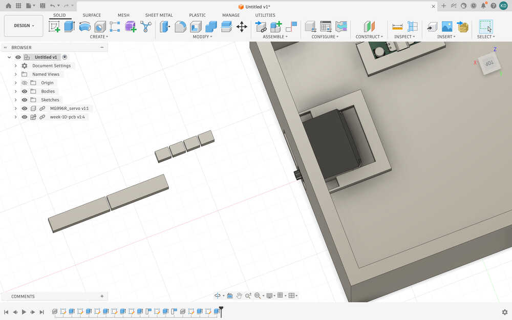
I made the connection part to the top part.
I created two parts to help the robot stand up. They're 5mm by 5mm and have a height of wr - t - sh/2. Without these, the robot would lose balance pretty easily.
I made these two holes so that the cables of the servos can come out.
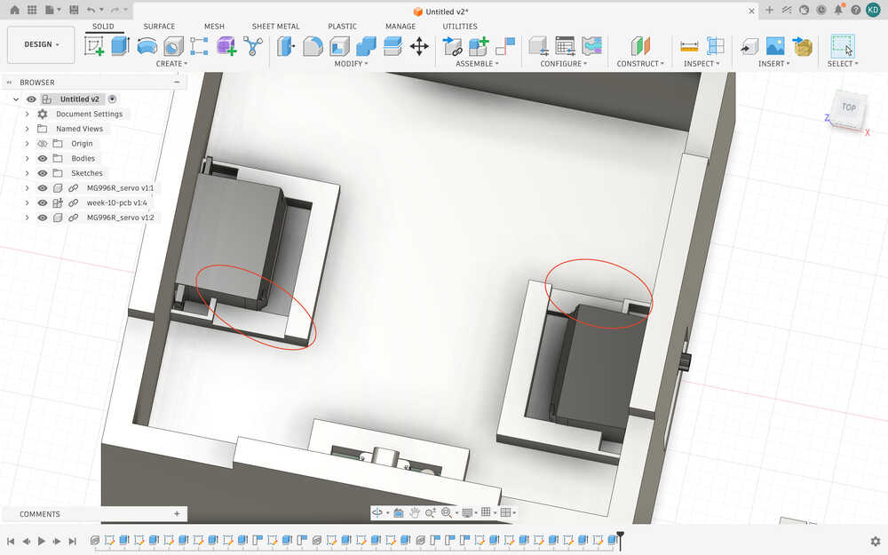
After starting the printer, I realized that the design wasn’t correct; the servo doesn’t fit and probably isn't that stable. I decided to use screws to fix the servo in place.
I reverted the changes I made to the servos.
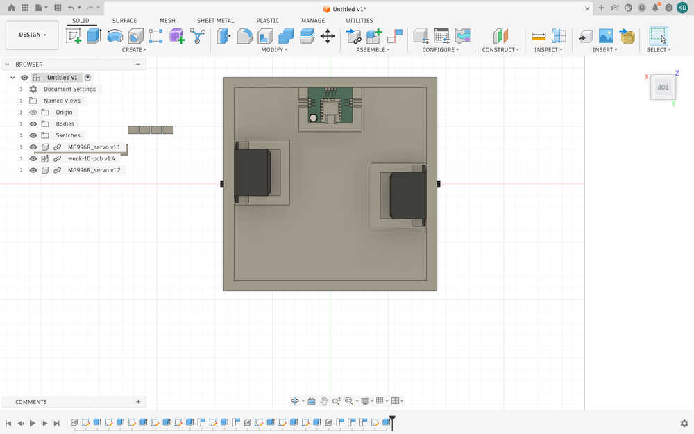
Apparently, the max width of the servo is about 40.698, so I added another parameter named swm, servo with max, which is equal to that value. So, I made the holes the servos will enter by using swm. Also, I added a 0.1 extra wideness to the holes so that the servos can get in easily. Right now, it looks like this.
I put the servos into the holes.
I opened holes for the screws.
Now, the design is finished.
These are the settings for the 3D print.
The design is out.
After comparing the size of the robot to some stuff, I realized that it was too big. So, I decreased some of its parameters.
Also, the parts couldn't really get in.
Here are the parameters I changed to decrease the size of the robot.


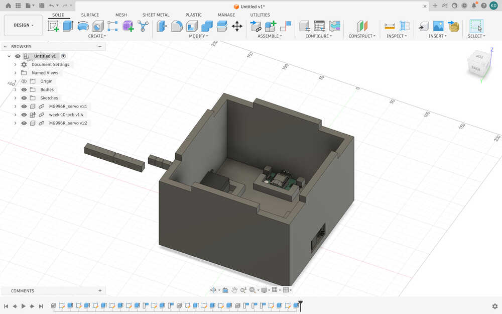
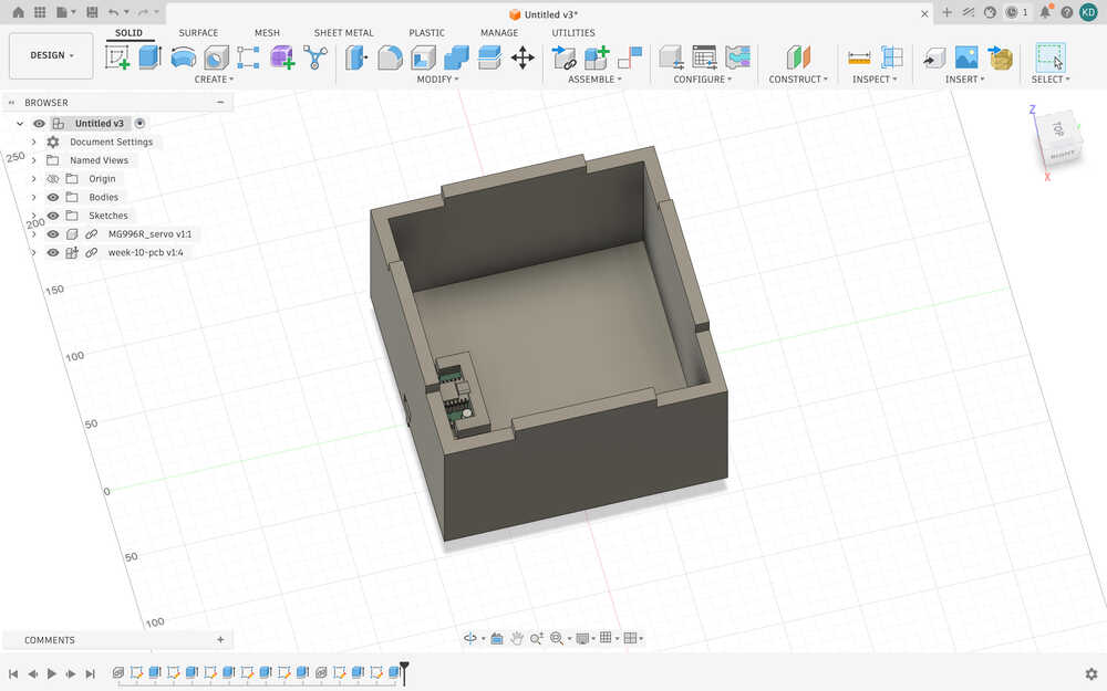
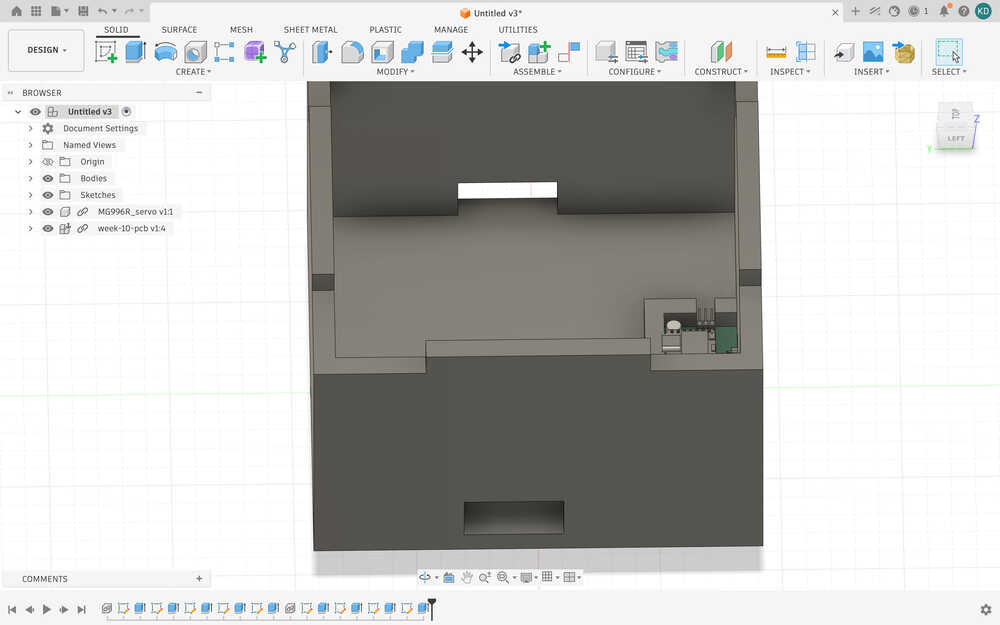
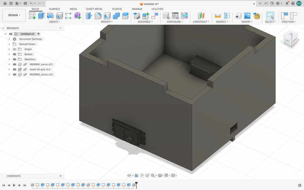
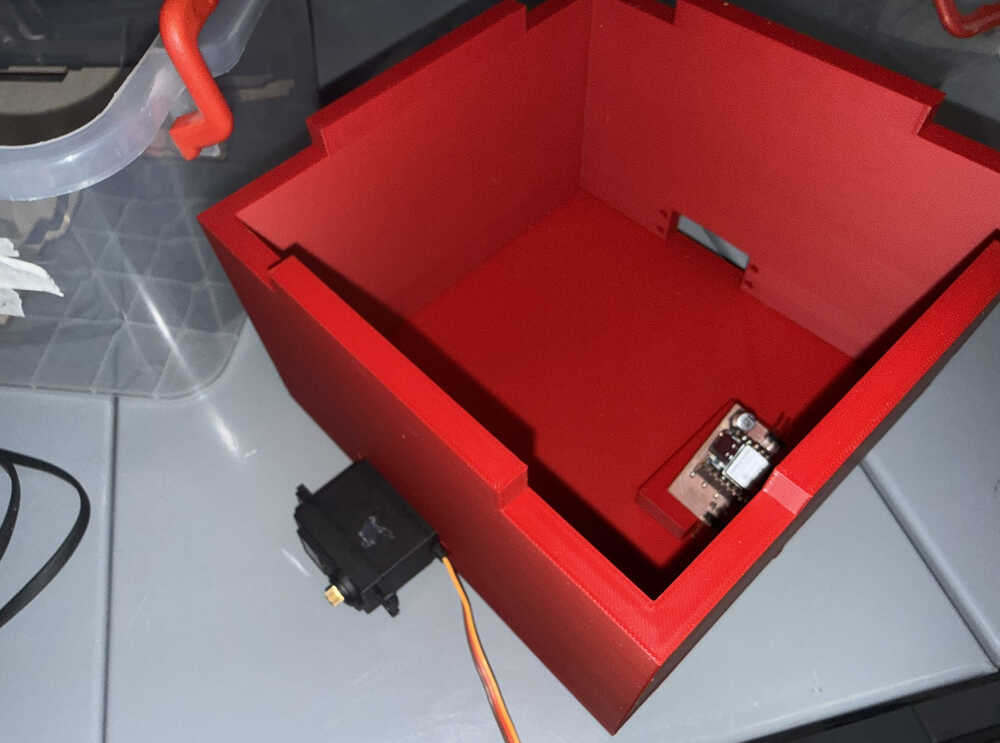
Here is the new design.
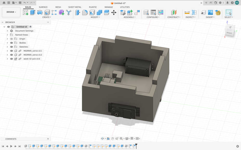
I decreased the overall size of the body, I remade the PCB part after measuring the size of the real PCB, and I increased the size of the servo holes so that they can slot in easily. I also changed the height of the robot to about half of what it was before.
This time, when printing, I didn't check the box for "on build plate only".
I'm really glad I made my design parametric.
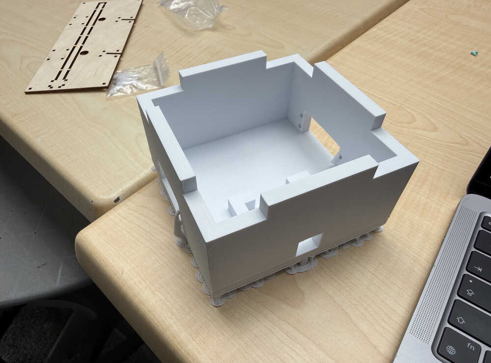
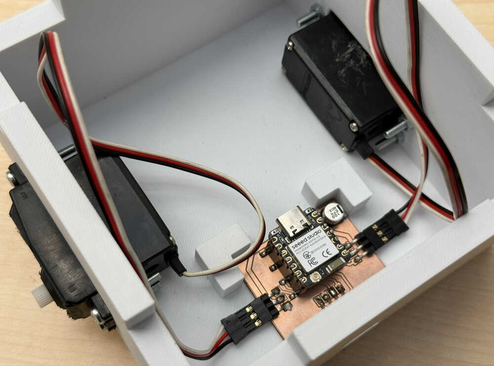
Assembling
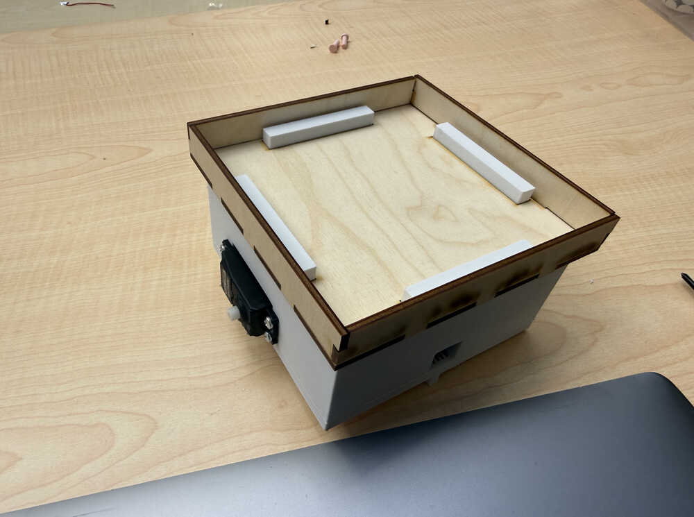
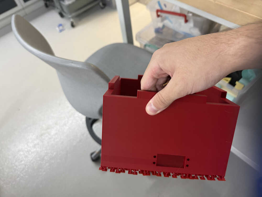
It's out:
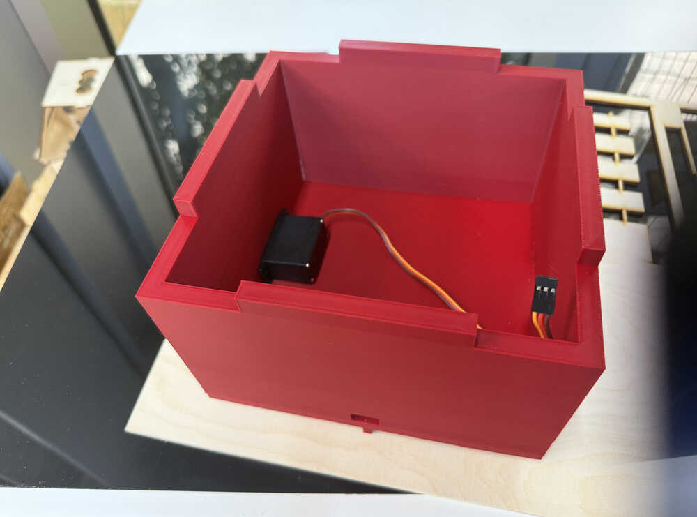
The parts I'll be assembling:
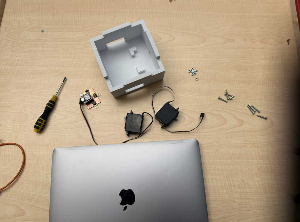
After screwing etc.
Files
Here are the files.