Week 13, Moulding and Casting
Table of Contents
- Overview
- Resources
- Group Assignment
- Mould 1
- Cast 1
- Mould 2
- Wheel
- Files
Overview
This week, I created a mould with the laser cutter and failed to create one with milling. I also tried casting the laser cut one.
Resources
- I used xTool Studio.
- I used Cuttle.
- I used Fusion 360.
Group Assignment
Here is the group assignment.
Mould 1
Idea
For my first mould, I'm planning on using a laser cutter. I decided on creating this icon:

I didn't really know what to create, so I just thought about this icon since it's from the game I played last night. Also, since it's not that complicated, I believe it's a good choice for this week.
Final Version
Process
First, I created the components I'll be using.
I imported the image I'll be using and I clicked "Trace Image".
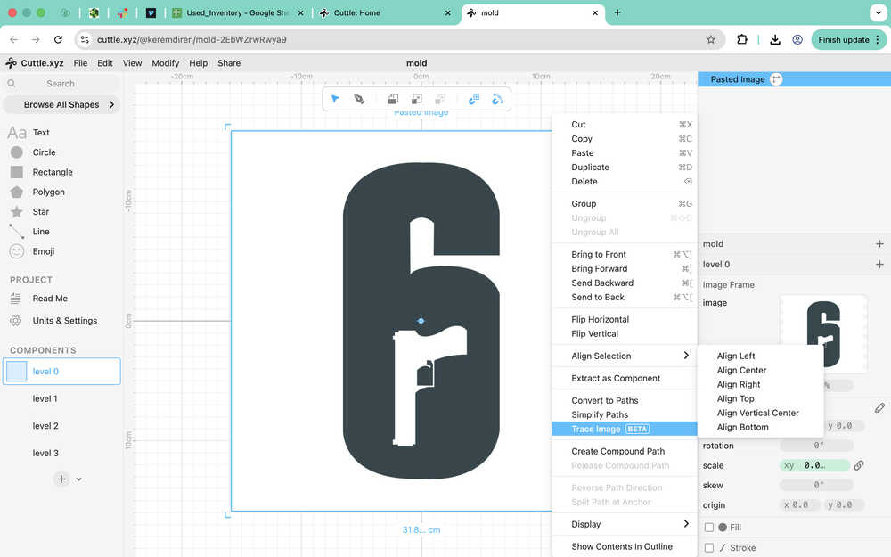
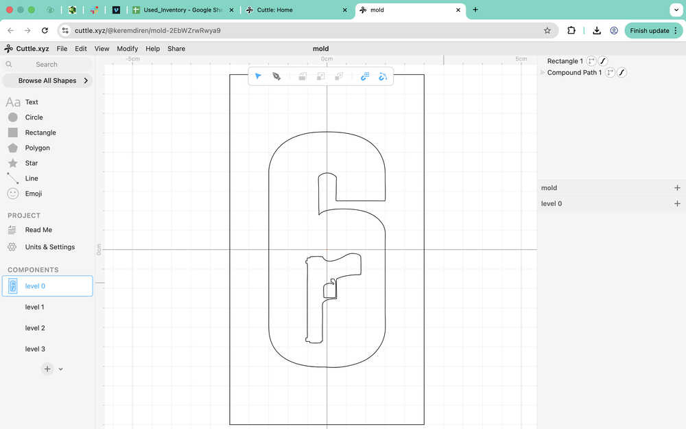
Then, I unfilled the image and deleted the white background. I also turned on the stroke so I can actually see the icon when I'm not looking.
I created the level 0 according to the dimension (after I decreased the dimensions to about 3cm to 6cm).
I added parameters to the design.
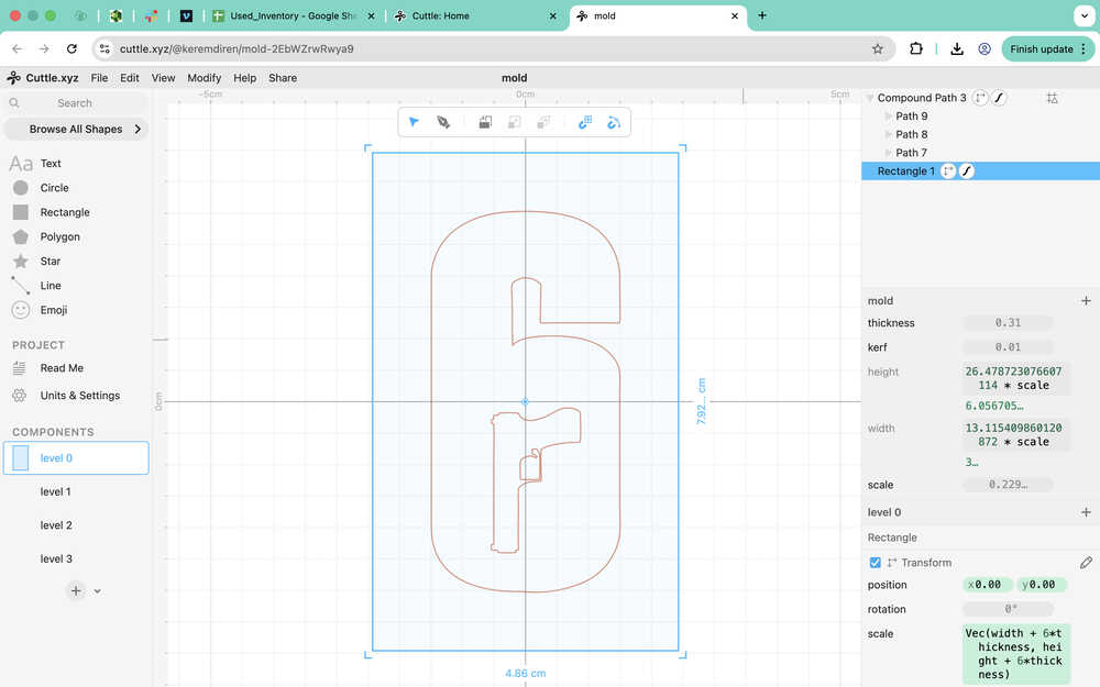
I added four holes that I'll make sticks go through so that the whole thing stays together while I'm casting.
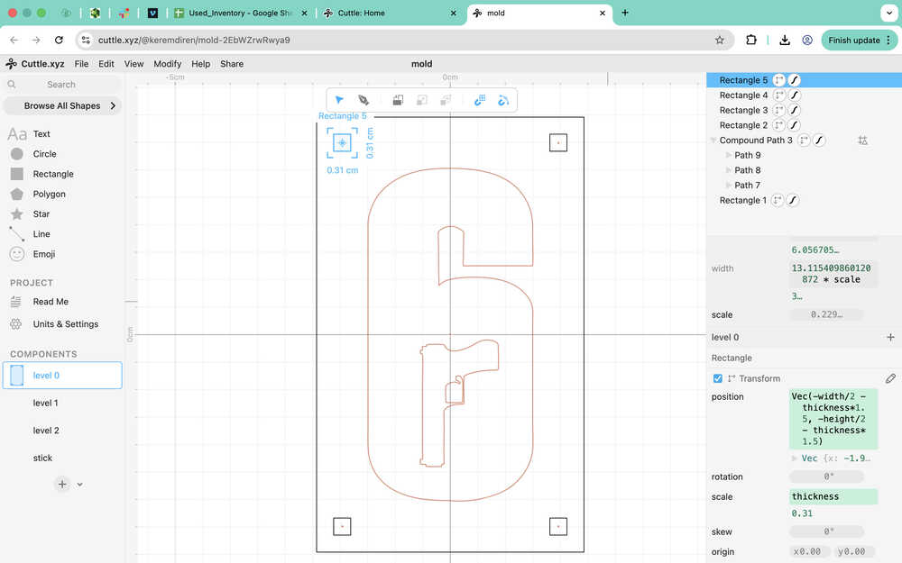
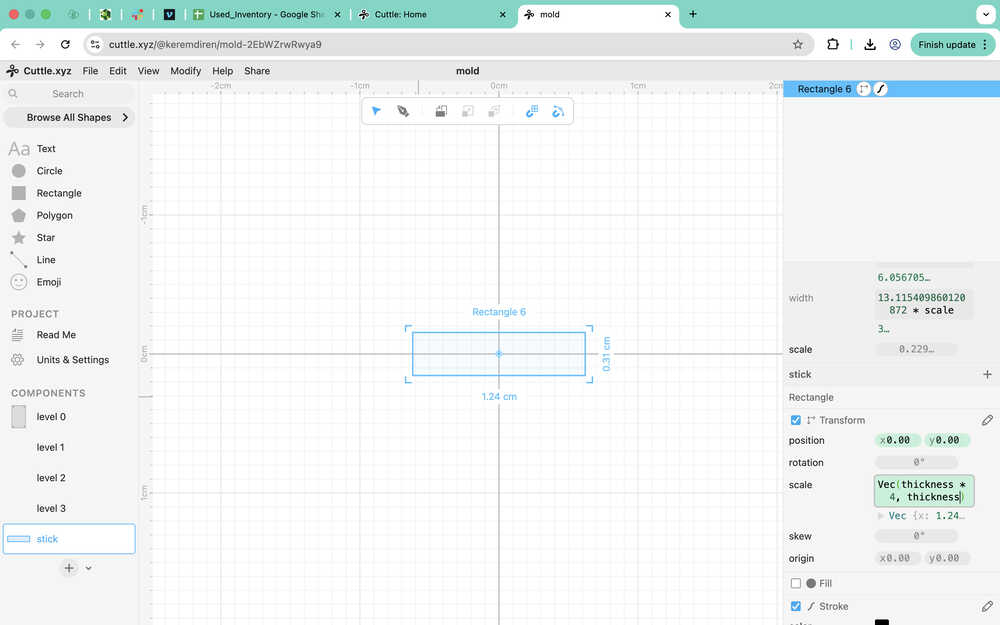
I created the design the sticks.
For the 1st level, I first imported level 0 and turned off the guide selection of the icon.
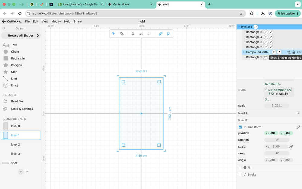
Then, I turned the stroke off and filled the inside of the icon with red.
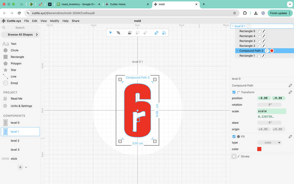
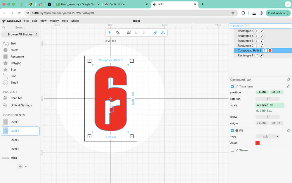
Then, I decreased the scale of the icon to 99% of its current version.
For the third level, I just imported the first layer and flipped it horizontally.
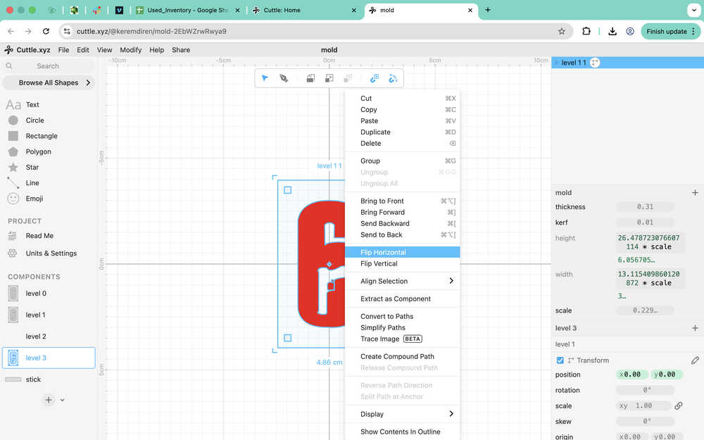
I realized that I should've made a copy of level 0 since the changes also affected it. This is why I took back everything and made the changes after copying the guide icon and pasting it, so that level 0 doesn't get affected.
For level 2, I imported level 0 and copied the icon out of it once again.
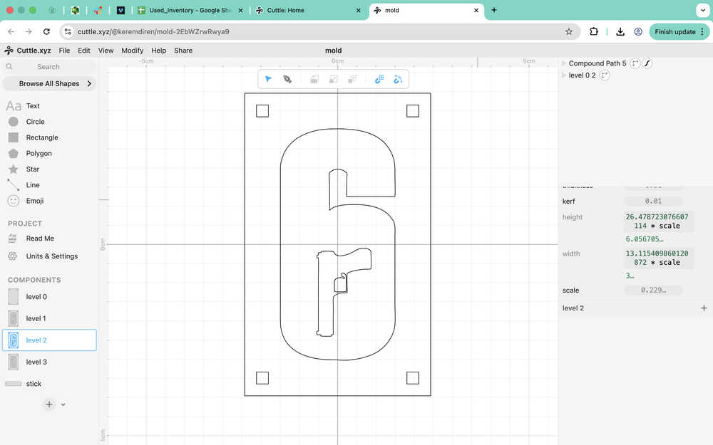
Currently, the gun in the middle of the icon would fall down if level 2 were to be cut. Though, I'll look into it after adding kerf to the design.
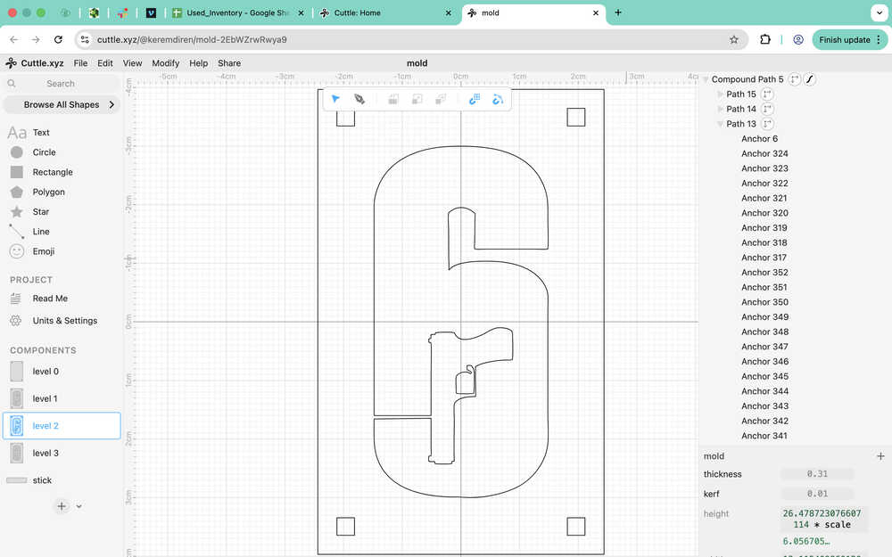
After adding the kerf:
As it can be seen in the video, I had to edit the icon's parts separately so that the kerf works correctly.
I decided to just make a thin line from the gun to the six. There'll be an empty hole on the side of the design, but I'll just fill it after the design's out. Also, I'll need to destroy the middle layer to get the thing out after casting.
After changing the design:
Unfortunately, this does not scale with the kerf, so it needs to be recreated whenever kerf changes.
I realized that I did the kerf wrong, so here's the new version.
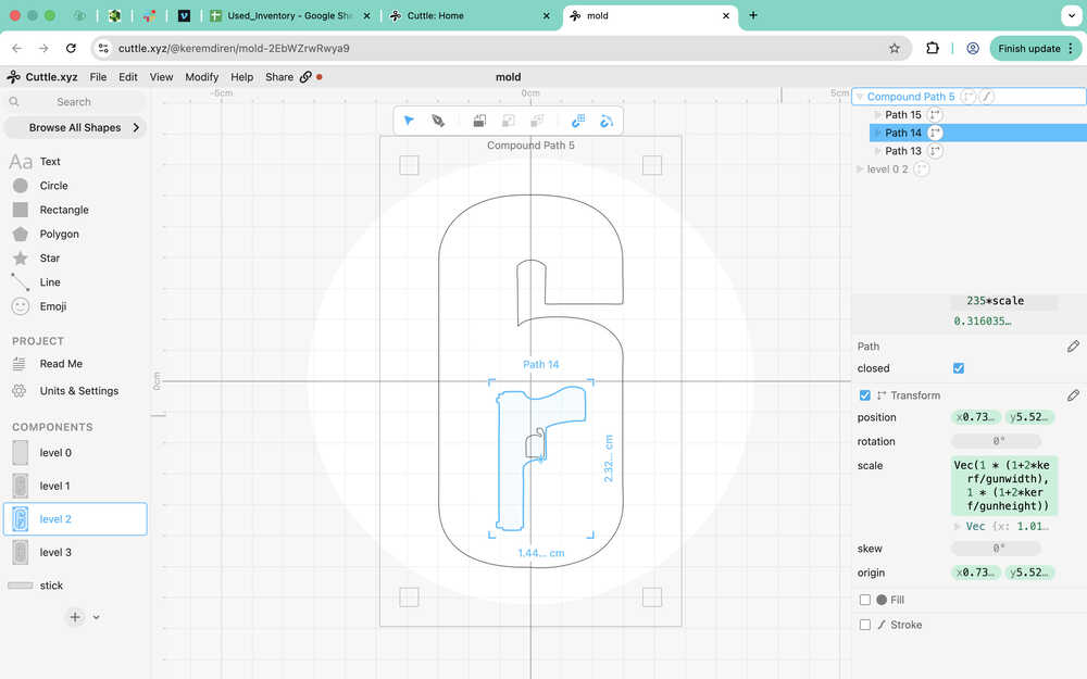
I also had to change the origin coordinates of the parts of the icon since I realized that they acted weirdly when I changed the kerf parameter.
I was able to make the gun-six connection scale according to the parameters after putting the thing shown in the image into the path 13.
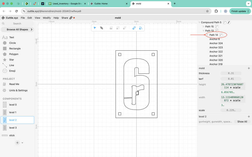
The design part of the first mould is now done. You can find the link to the design in the files part of this documentation.
Now, I sent the project to the printing computer.
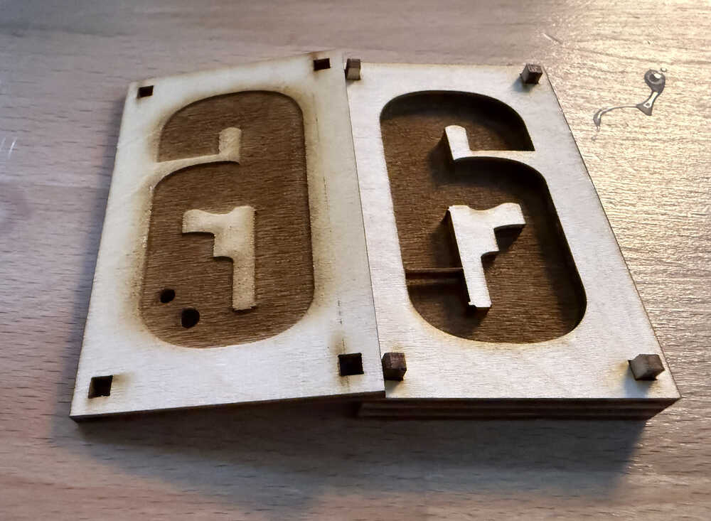
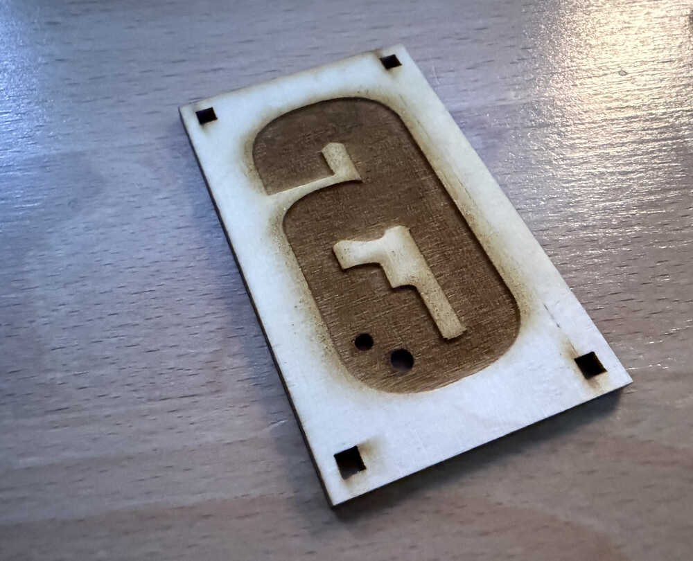
Cutting:
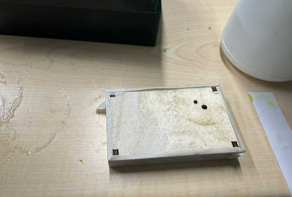
Mould is out.
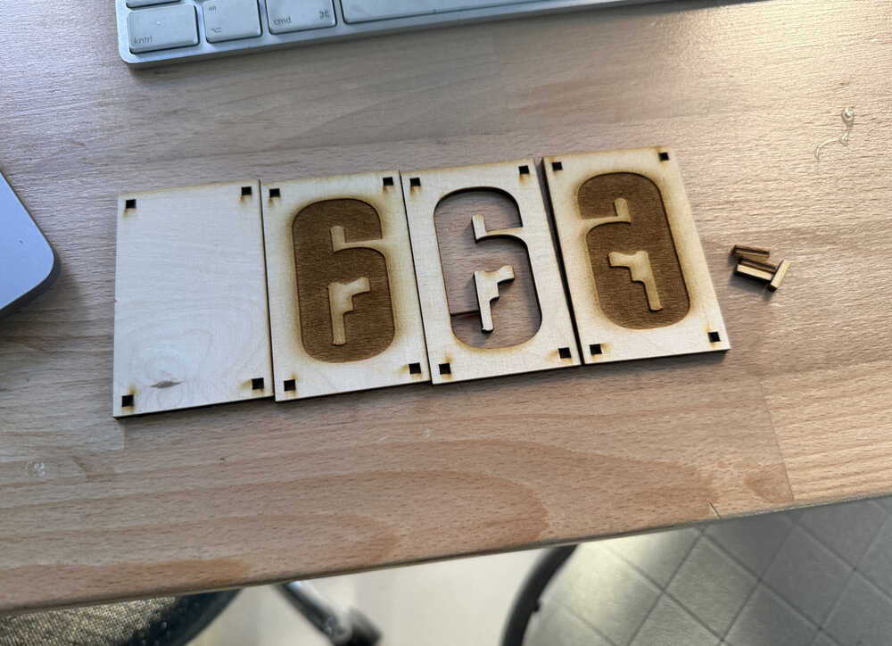
I made a hole to make it possible for me to cast.
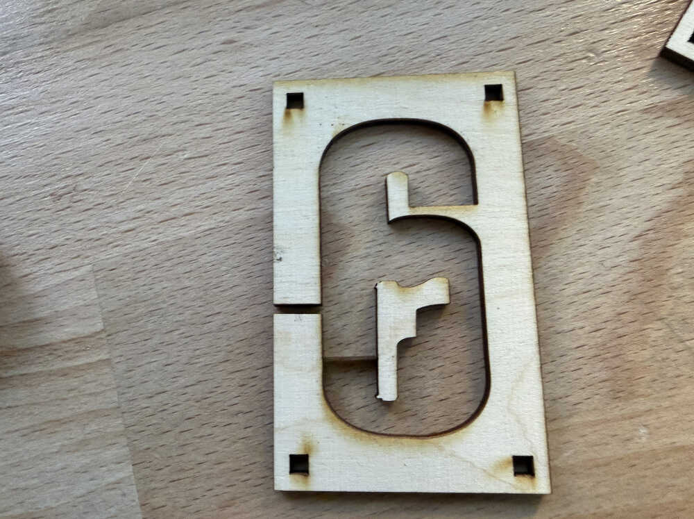
Because I was worried about how the air would exit, I opened another hole on the side. However, while the hole was being opened, I realized that opening another hole would basically cut out the part between the two holes. I was too late, so I cut the middle piece again.
Now, I decided to open the two hole on the back side, so I did that (after re-cutting the middle part).
Cast 1
You can find the safety data sheet here.
After applying pressure from the top and bottom (using a tool), I taped the sides so that the liquid doesn't get out and so that the mould doesn't lose shape.
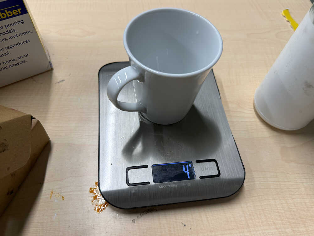
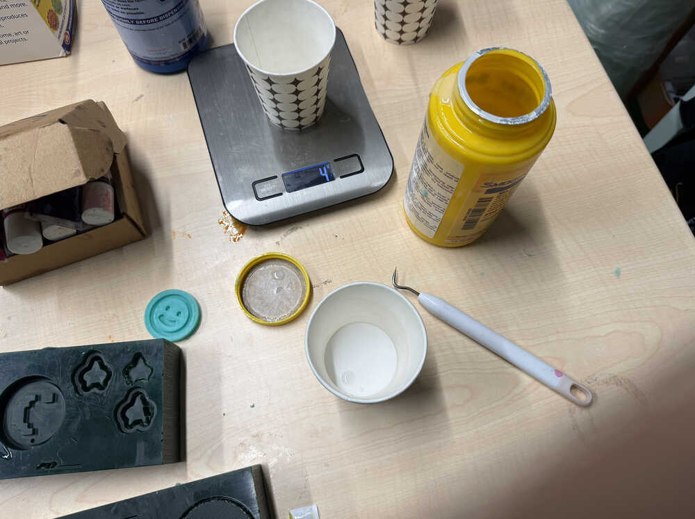
From what I calculated, this mould should have a volume about 15.5* 0.308 * 1.5 = 7.161cm^3. After I sent this information to ChatGPT, it said that I needed about 3.9g of each resin type to cast.
Part A:
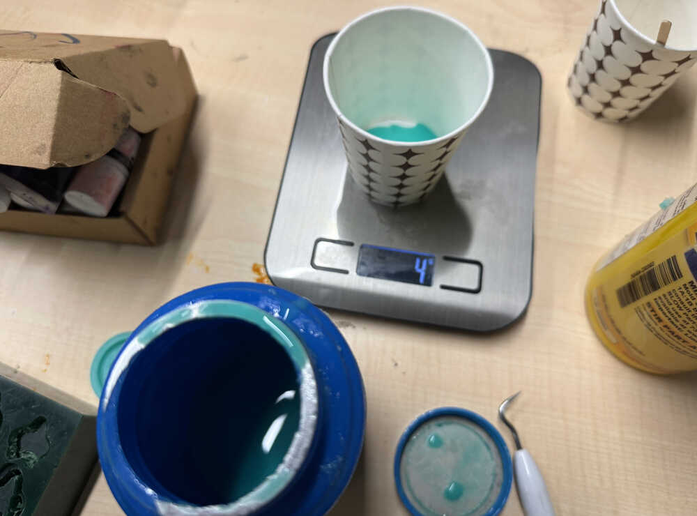
Part B:
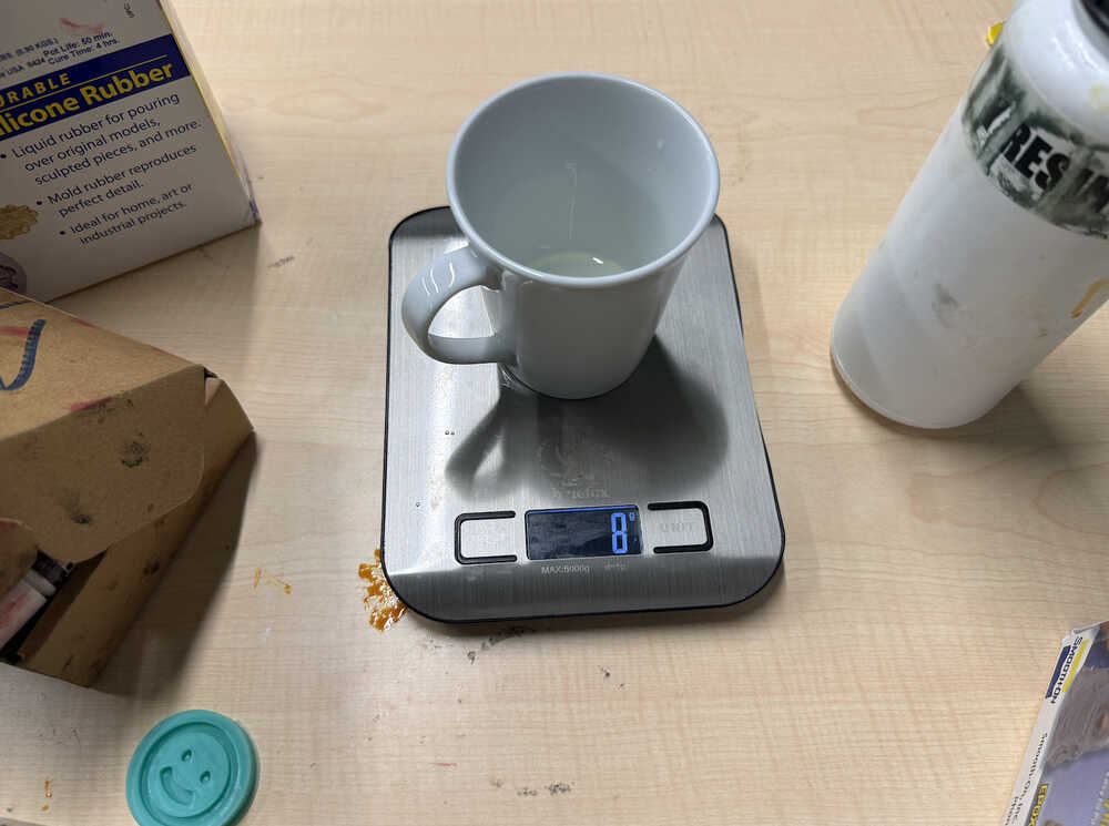
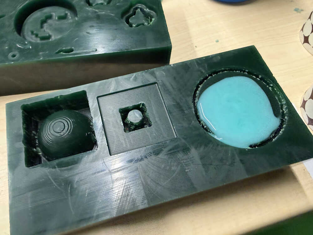
After the mould is filled.
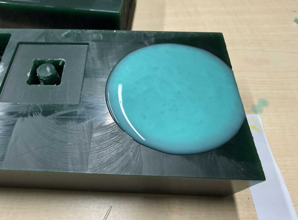
You may have noticed that there's a bubble of resin on top of the mould. I poured some extra so that, in the case that the wood absorbs some of the liquid or some air comes out from inside the mould (which would create some empty space in the mould), the cast doesn't lose shape. What I mean is, the resin in the mould could decrease or the mould's shape could distort, so the extra resin on top of the mould is there to fill the mould back up.
It's out:
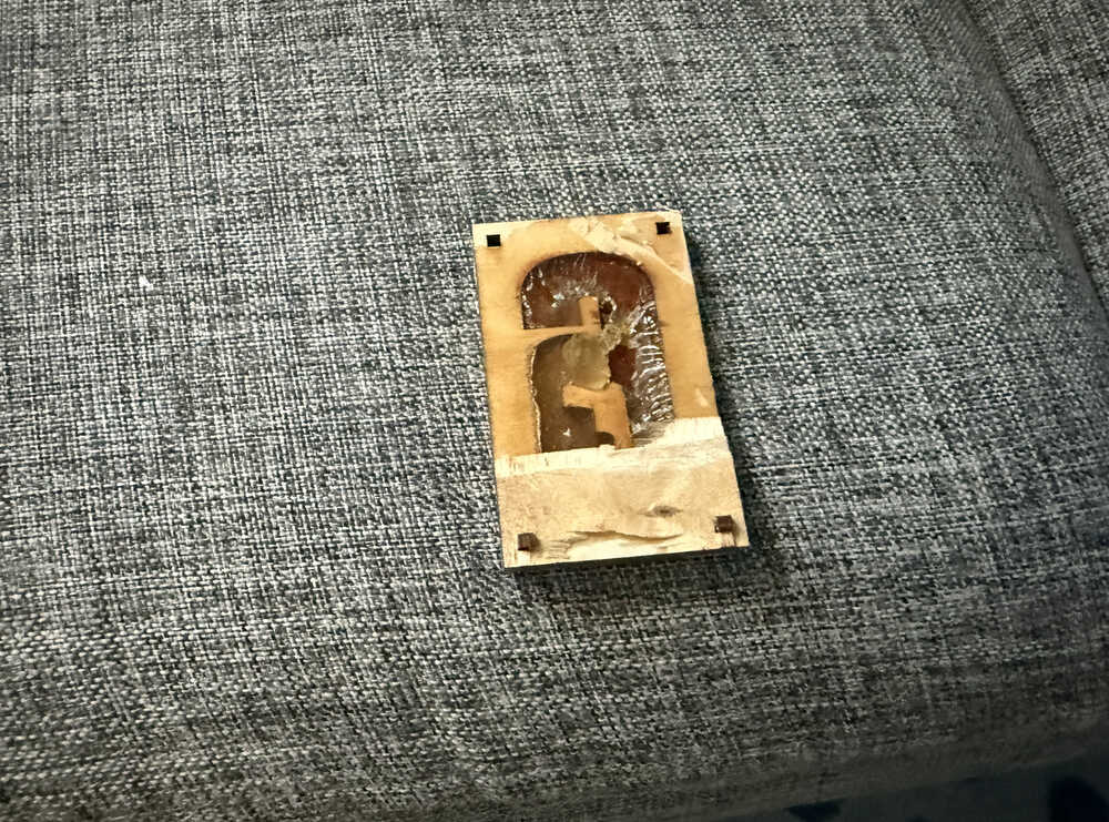
It had some parts stuck to the top layer of the wood. So, when I was taking it out, some of the cast broke of. Also, I had a hard time separating the layers, too.
Mould 2
Idea
For my second mould, I'll be creating a mushroom. I don't really have a reason for this. I just saw a mushroom and decided to create a mushroom mould.
Process
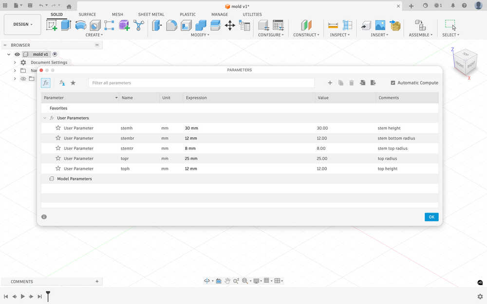
Here are the parameters I'll be using.
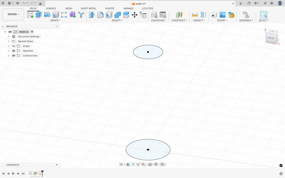
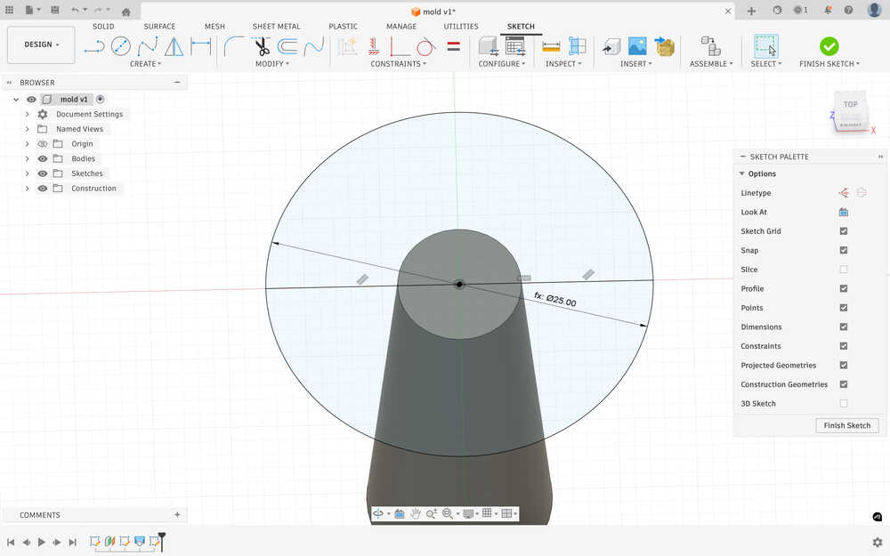
I created a circle sketch equal to stembr.
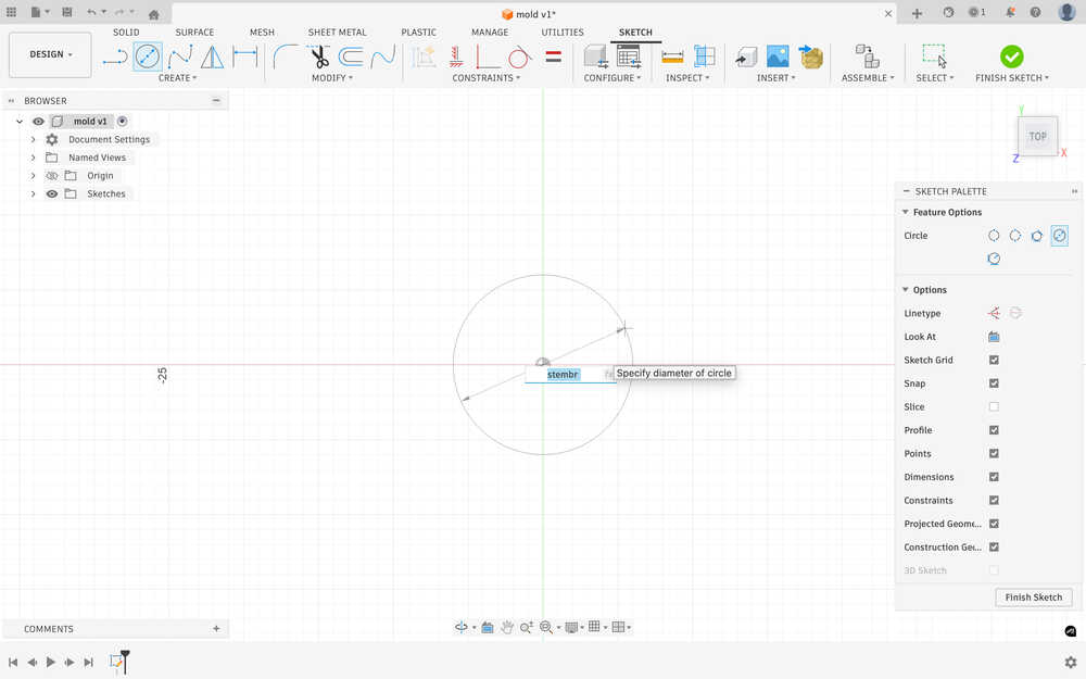
While doing this, I realized that I planned everything according to diameters, so I changed to "radius" in the parameter names to "diameter".
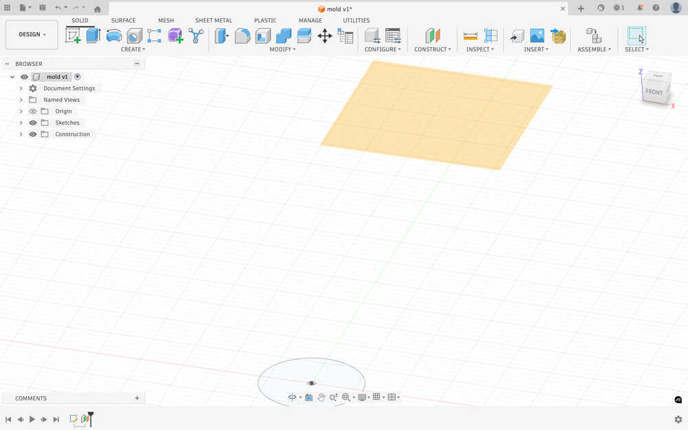
I created an offset plane that is stemh above the ground.
I sketched the second circle.
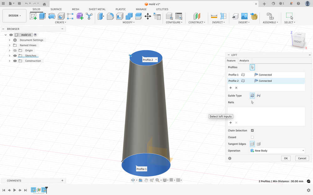
I used loft to make the stem.
I sketched a circle on the top of the stem so I could start creating the top.
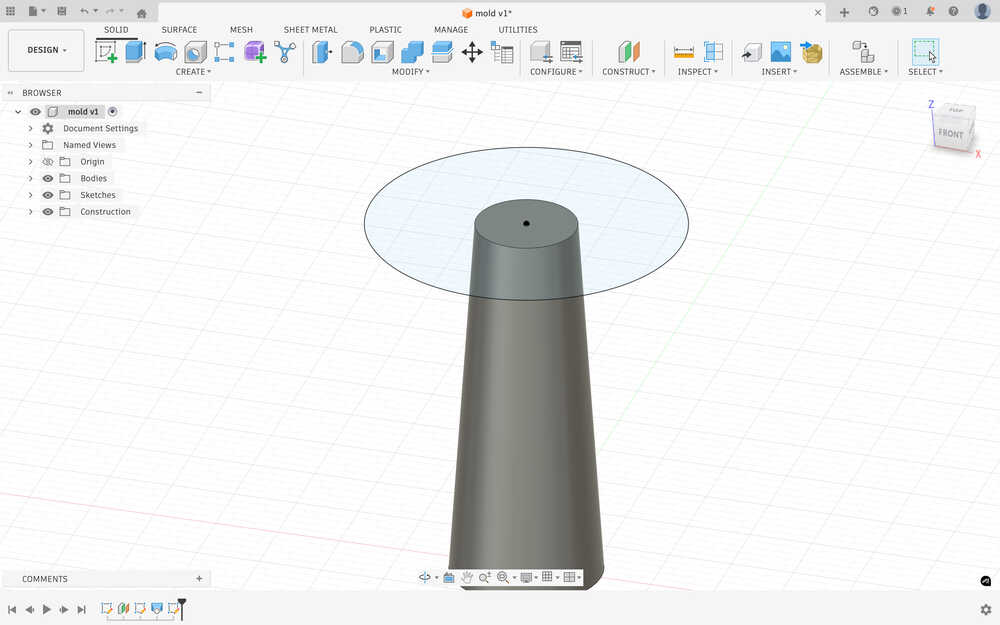
After trying some stuff, I realized that I did the sketch wrong. New sketch:
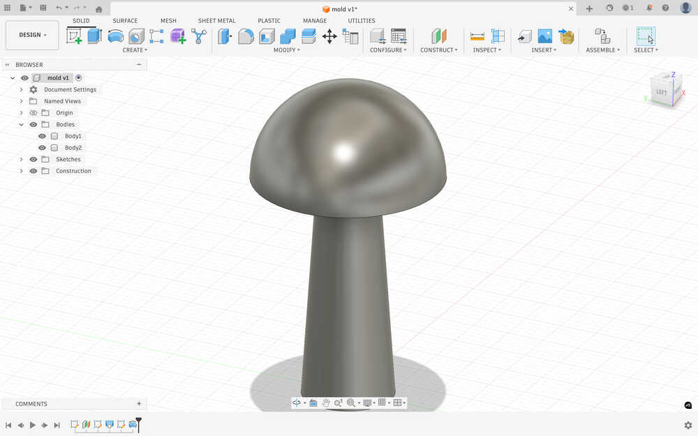
I used revolved to make the top part. As you can see, the two are different parts. You see, I'm planning on creating a two piece mould, so I have to do this to make it easier for me to prepare.
Because I thought the top part was a bit too small in radius, I increased the topd parameter.
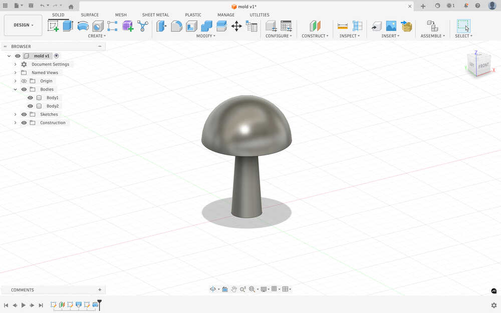
I also deleted the toph parameter since I realized that I didn't need it.
After using combine to make the negative space on a block, this is how my design looks.
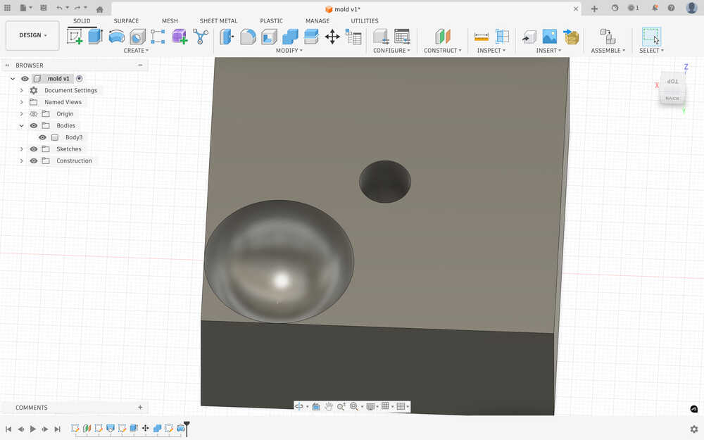
I had to recreate the cap of the mushroom since I couldn't really move it for some reason.
Some time later, I realized that what I've just designed was the mould itself. I was supposed to make something to make the mould, not the mould itself. So I fixed it.
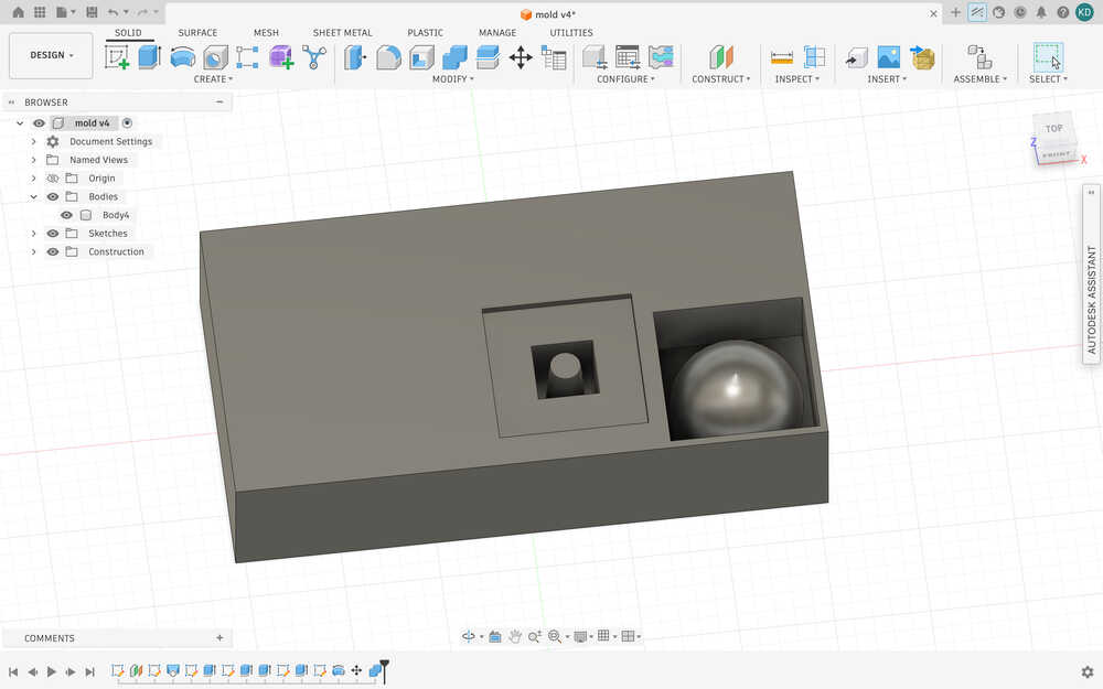
I also set created parameters equal to the material I'll be milling while doing this. Also, I had to put the position of these in a weird way since the material I'll be using was previously milled, so I had to spend some time finding an appropriate position to put my things.
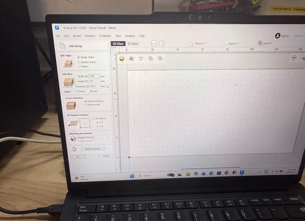
I exported the file as stl and sent it to tje computer with VCarve installed.
I created a new file with this job setup.
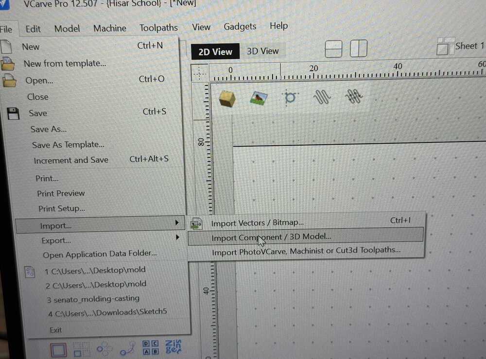
I imported the .stl file.
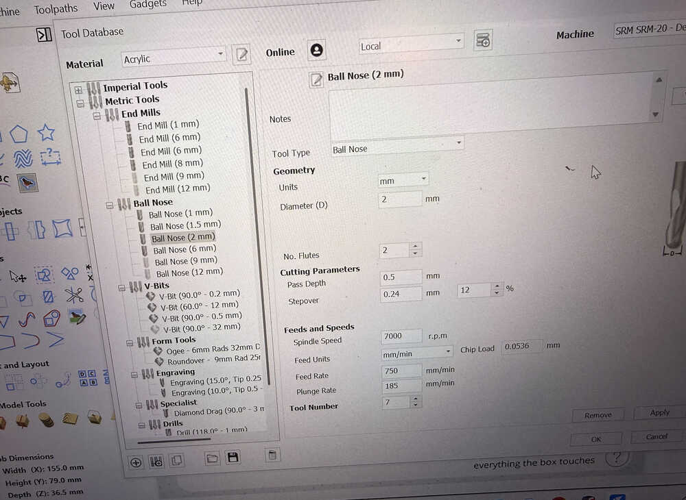
I set the parameters of the tool I'll use.
I generated a roughing and finishing toolpath.
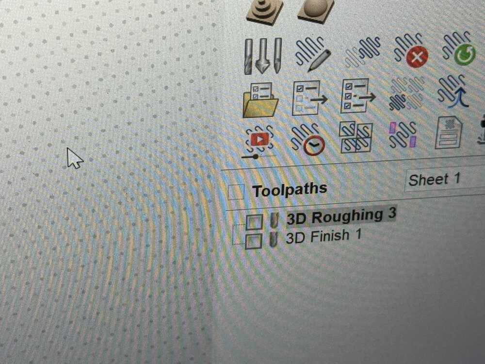
I started the machine.
Because my mould slightly pierced another mould, I had to remake the mould; however, there was no space left, so I used another wax block.
This time, the tool came out while it was milling. The thing isn't completely done. I'll need to mill it again.
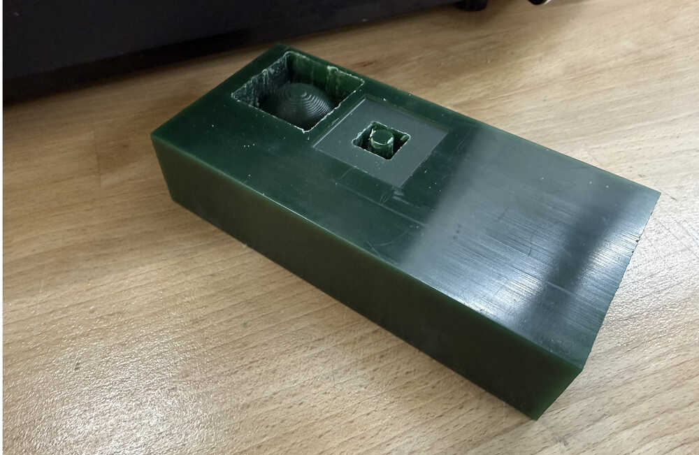
I decreased the size of the mould and started the mill again. However, the tool got stuck in the design once again. I think this happened because the space around the negative part is only 1mm in the design instead of 2mm, which is how much the tool's diameter is.
Wheel
Idea
This is me creating a casted wheel for my final project. I'll cast two wheels and they'll have a 50mm diameter (25mm radius) and will be 10mm thick (though I later changed the thickness to 5.5mm).
Final Version
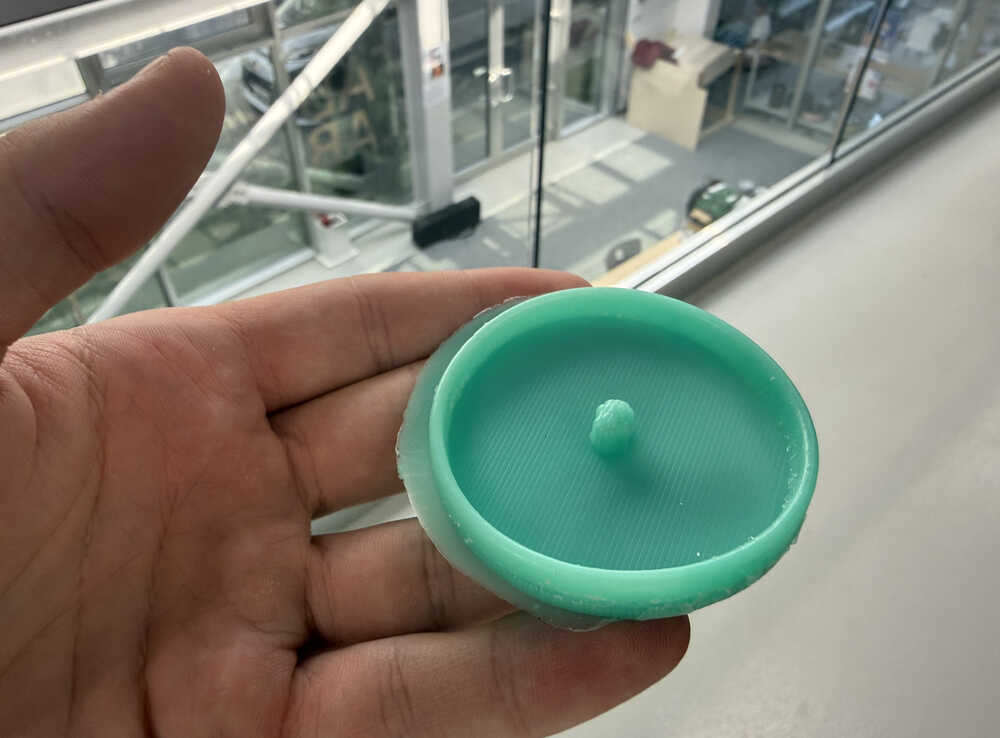
Mould
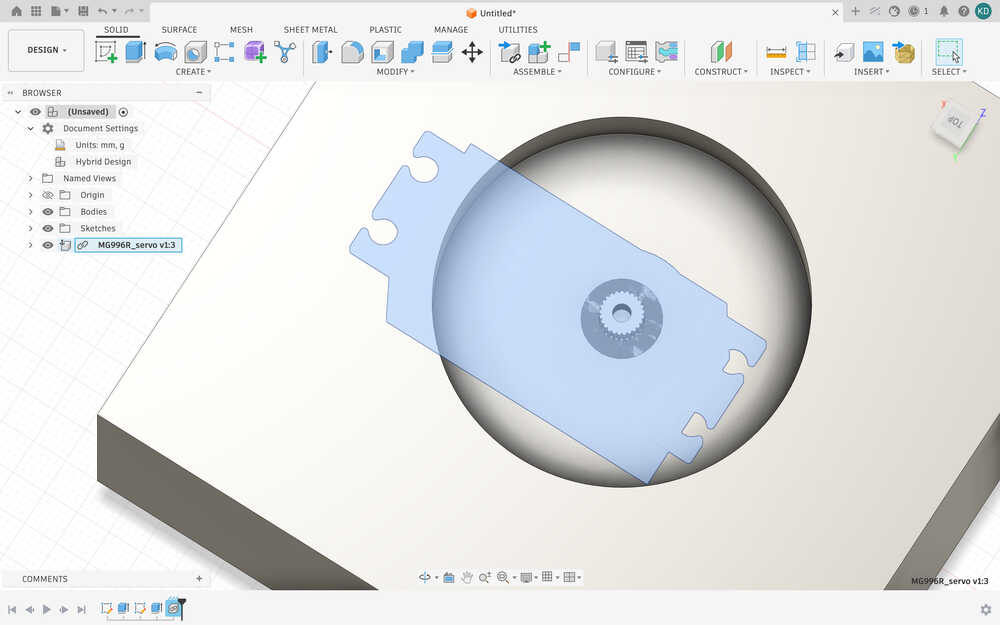
I started by importing the 3D model of the servo I'll be using to turn the wheel.
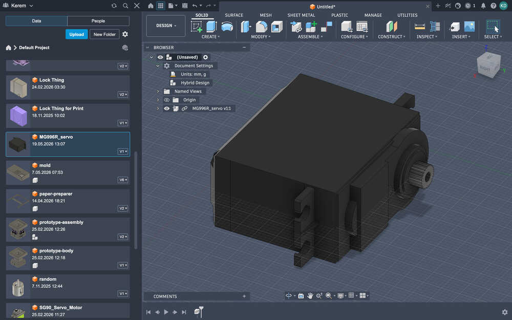
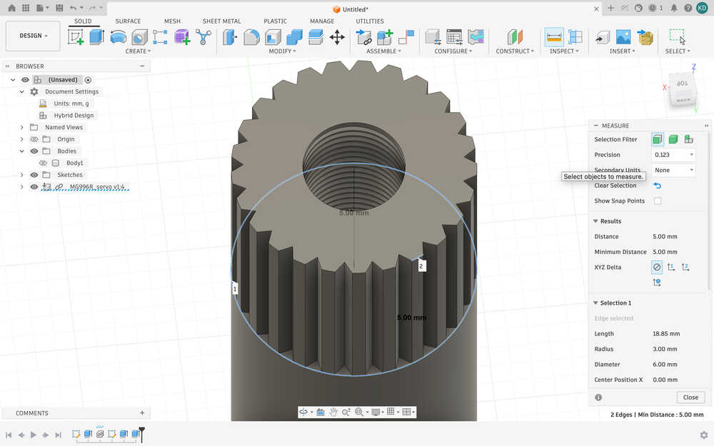
Using "measure", I learned that the diameter of the servo is 6mm and that the length of the turning part is 3.5mm. I added the following parameters along with them.
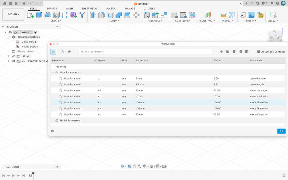
The wx, wy, and wz parameters have temporary values. I want to measure the wax once more before milling it.
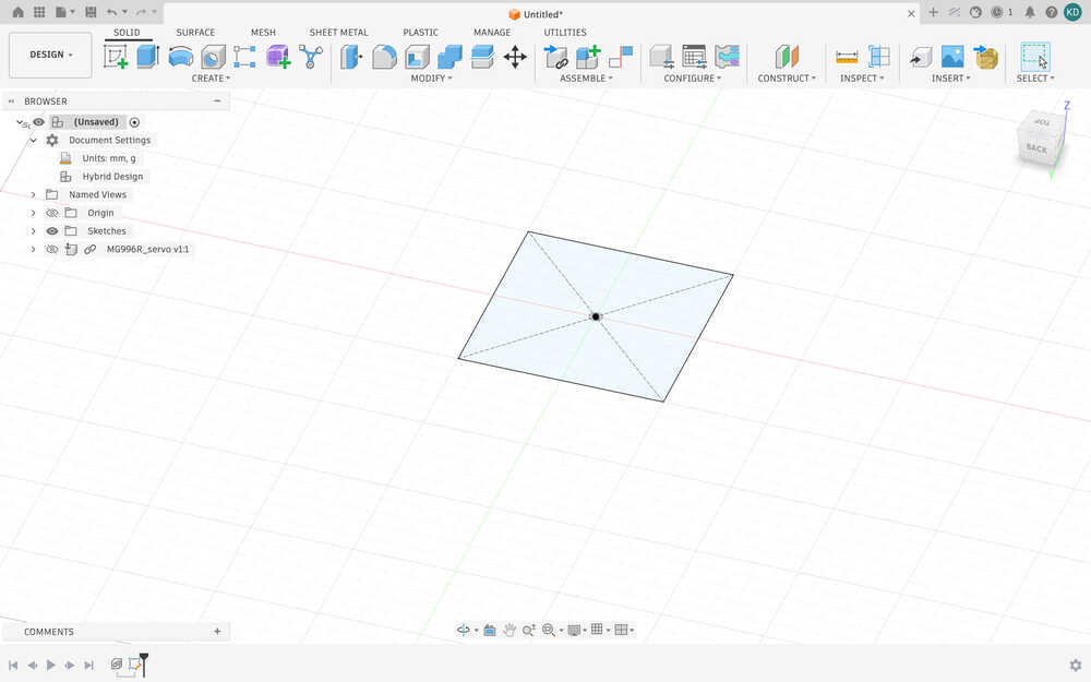
I created a sketch that's wx by wy.
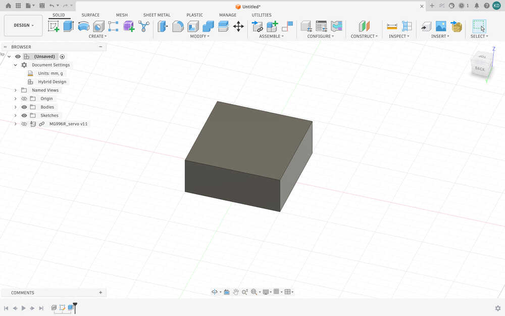
I extruded it by wz.
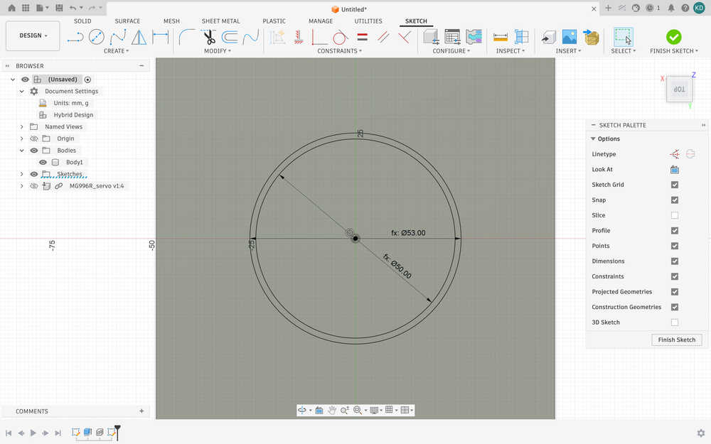
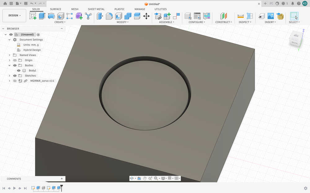
I created another sketch on top of the block. The sketch is a circle with 50mm diameter. I extruded it by -10mm.
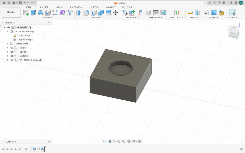
I moved the servo so that its turning part is in the middle of the cut part.
From ChatGPT, I learned that the M3 screw was needed for the servo I'll be using. I decided to make the thickness of the wheel (and thus the wt parameter) 5.5mm.
Also, I realized that I was doing the design wrong. So, I reverted the changes I did and sketched this.
I extruded the inner circle by -2mm and the outer circle by -(wt+2)mm.
I realized that this part is 5mm, so I changed the sl parameter to 5mm.
I also added a parameter called m3, which represents the diameter of the screwing part of the M3 screw, which is apparently 3mm.
Using outline, I made an outline that's 0.05mm larger than the teethed part of the servo.
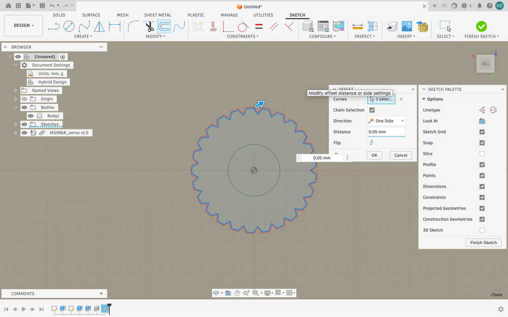
I cut that part by sl (5mm).
I made another hole with m3 + 0.05mm (3.05mm) diameter and wt - sl (5.5 - 5 = 0.5mm) length.
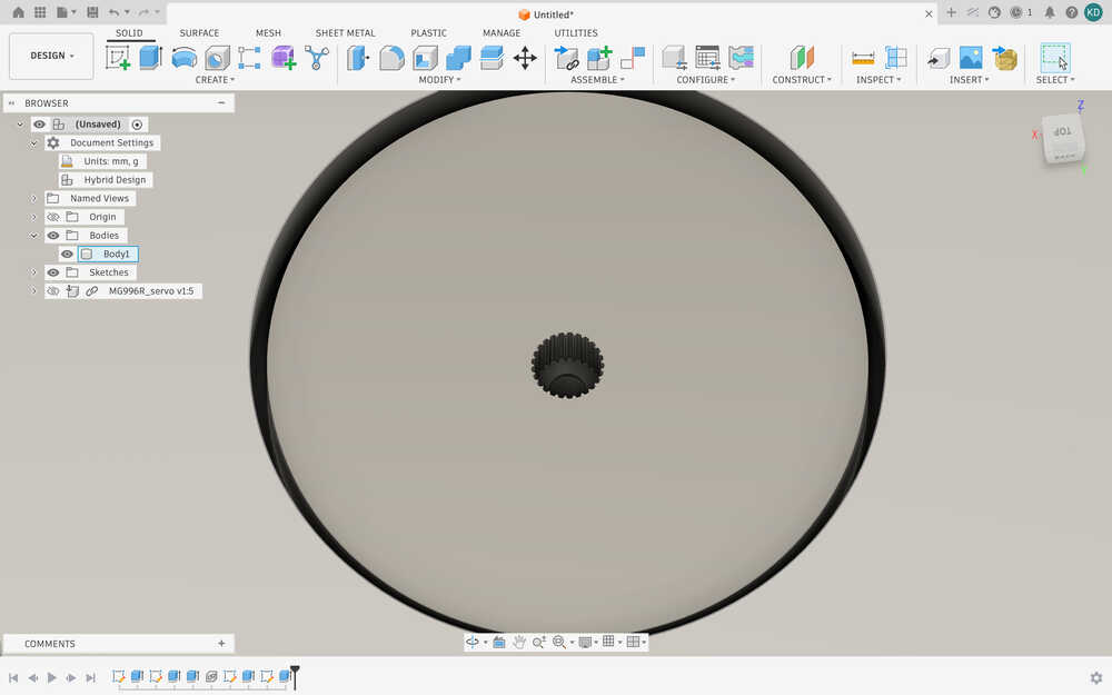
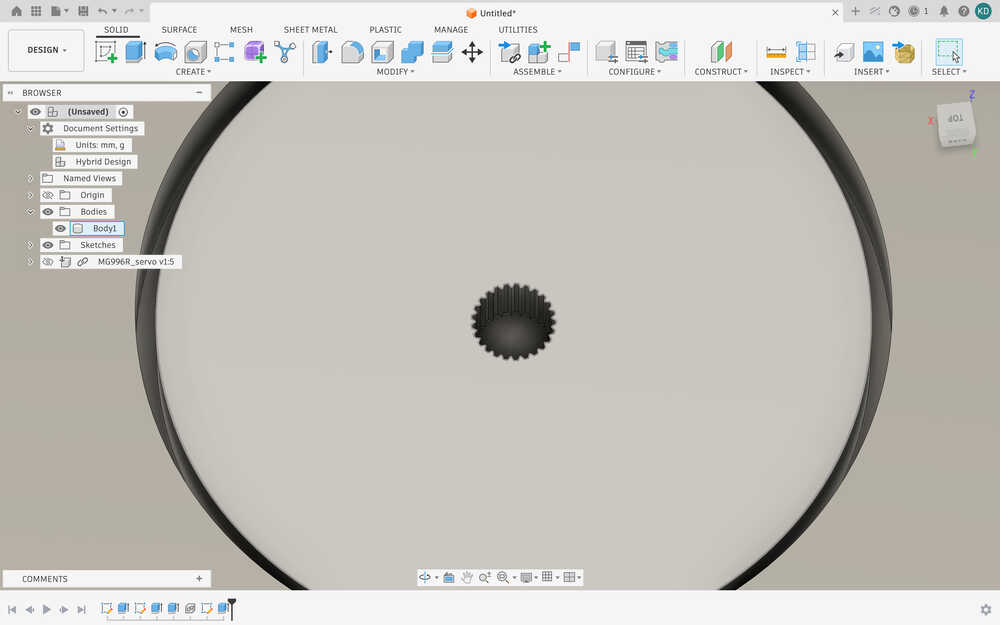
I realized that the hole in the middle was a bit too shallow to be equal to sl, so I checked the sketch and, apparently, the sketch was 4mm above where it should have been. So, I fixed it.
The design is done. I'm afraid, however, that I might need to change the design because the milling machine might not be able to properly cut the teethed part.
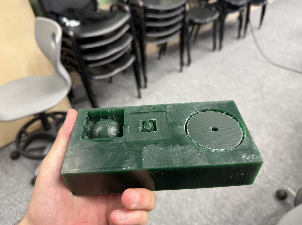
The wax is 79mm by 165mm by 36mm. I changed the design accordingly and cut the wax.
The wax after it is cut.
The thing has a volume of 165x79x36mm^3 - 4.624E+05mm^3 = 6.860mm^3. From ChatGPT, I learned that I'll need about 4.05 grams of each material to fill my mould.
Part A:
Part B:
The substance wasn't enough.
I made a little more and poured it:
Now, it has too much, so I wiped the overflowing parts with a napkin and popped some of the air bubbles.
It is out:
Cast
I poured in the resin mixture.
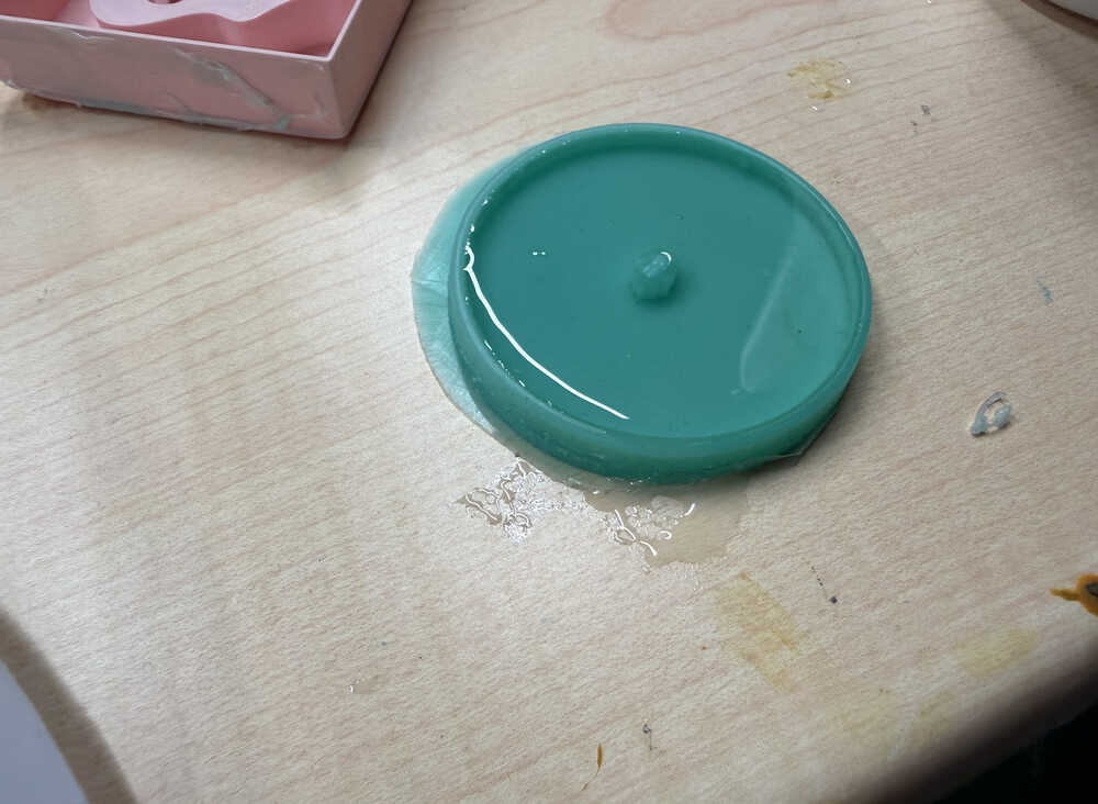
It's out, but probably because I messed up the ratio, only a thin layer was solidified and the remaining was still liquid. I'll try again.
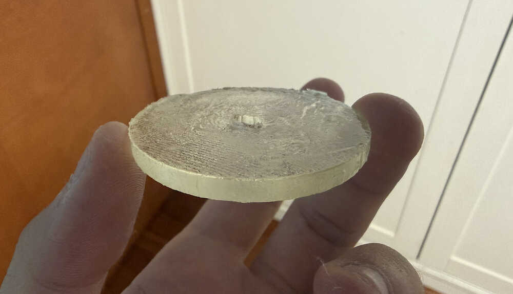
It's out:
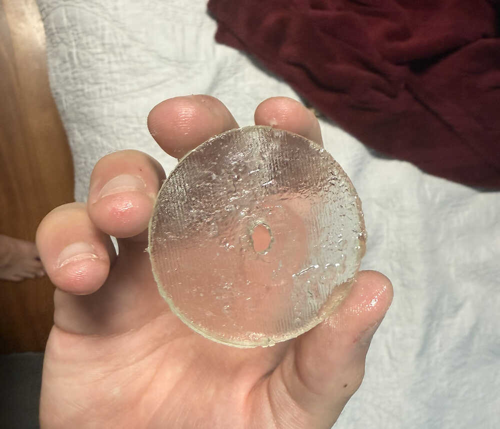
After the cast solidified, I decided to wash it before taking a photo, which caused the surface to look like this since the very top was probably not fully solidified. However, since most parts were solidified the wheel was ok. Basically, most parts still have a thickness of 5.5mm, but some parts have a thickness between 5mm and 5.5mm, so it's mostly fine. Also, the bottom part was fully fine even after washing it, probably because it was the first to solidify. I may or may not use this wheel for my final project. I mean, it works, but, if I have the time, I rather have a proper wheel. Also, I may use a harder casting material than this for the wheel since the wheel will carry the robot; although, this may be hard enough on its own.
Files
Here are the files.
This is the mould I designed from 2D.