Week 12, Mechanical Design, Machine Design
Table of Contents
- Overview
- Resources
- Group Assignment
- Enclosure
- Sticker
- Paper Preparer
- Files
Overview
This week, I created an enclosure for the machine, I created some stickers, and I created a thing with 3D design and the 3D printer to help with preparing paper for the plotter to use. I also learned how to use a machine named BN-20A.
Resources
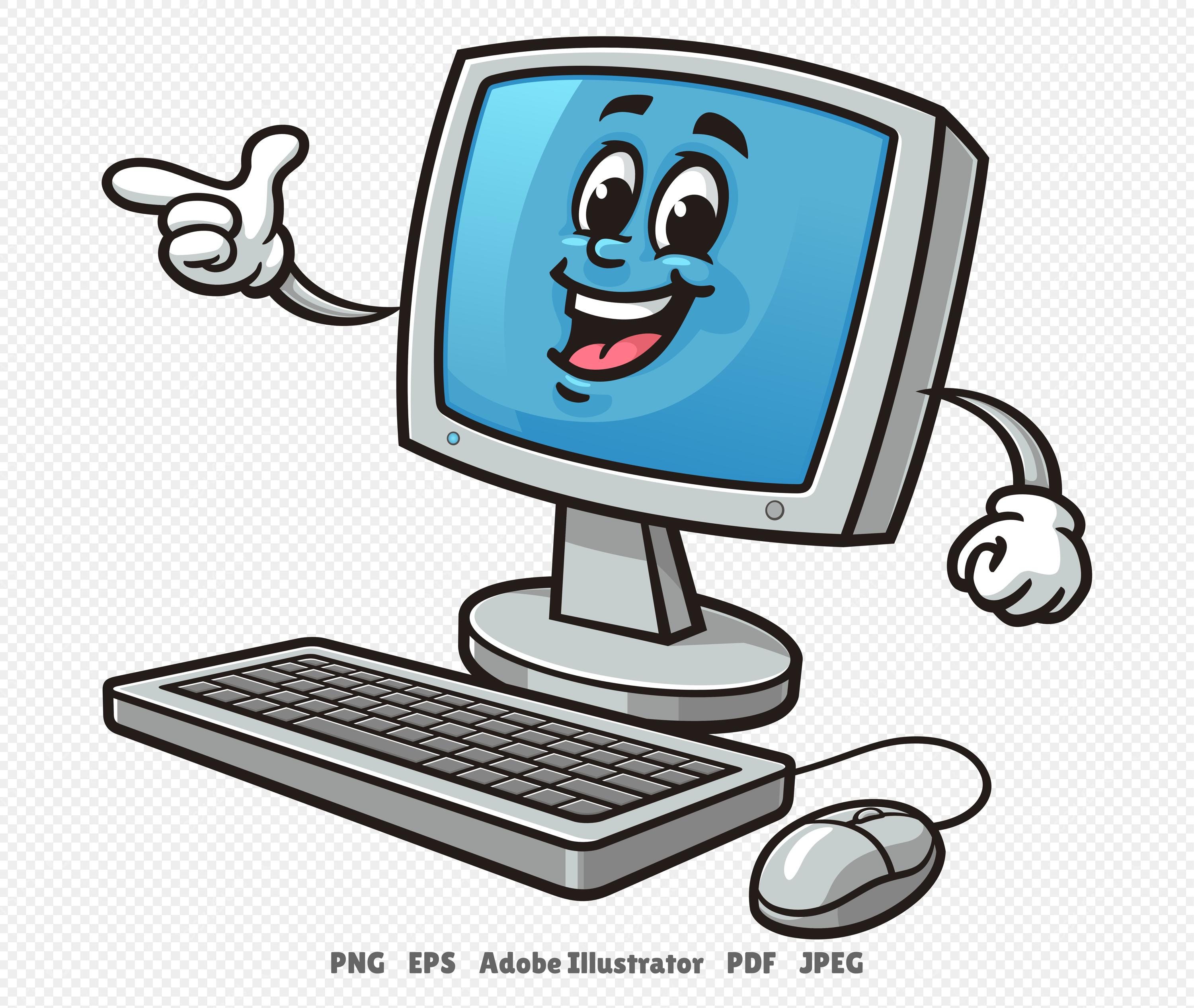
- This is the computer image I used.
- I used Cuttle to create the enclosure.
- I used Inkscape for the stickers.
- I used Fusion 360 for the 3D design.
Group Assignment
This is the website for our plotter machine.
Enclosure
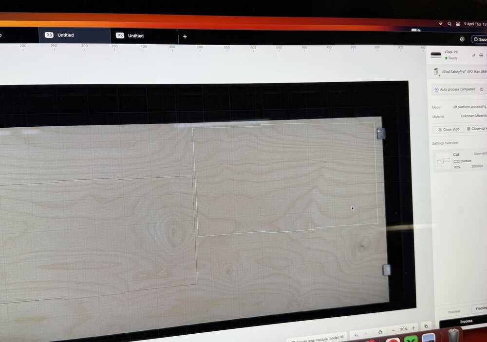
I first sent the design to the laser cutter computer.
I arranged two of the three pieces I'm supposed to cut. I also set the speed and power parameters to 30 and 70, respectively.
The machine is cutting:
I cut the other one with the same parameters. Here are the pieces I just cut:
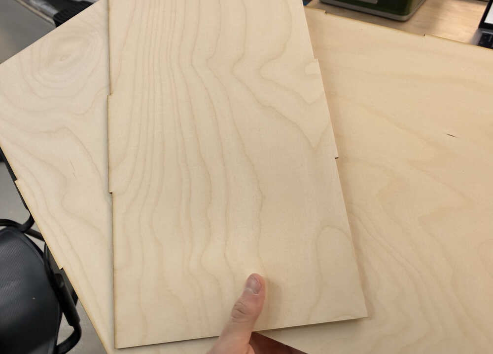
The pieces didn't fit, however.
I added the kerf parameter to the design.
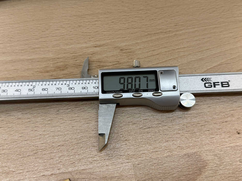
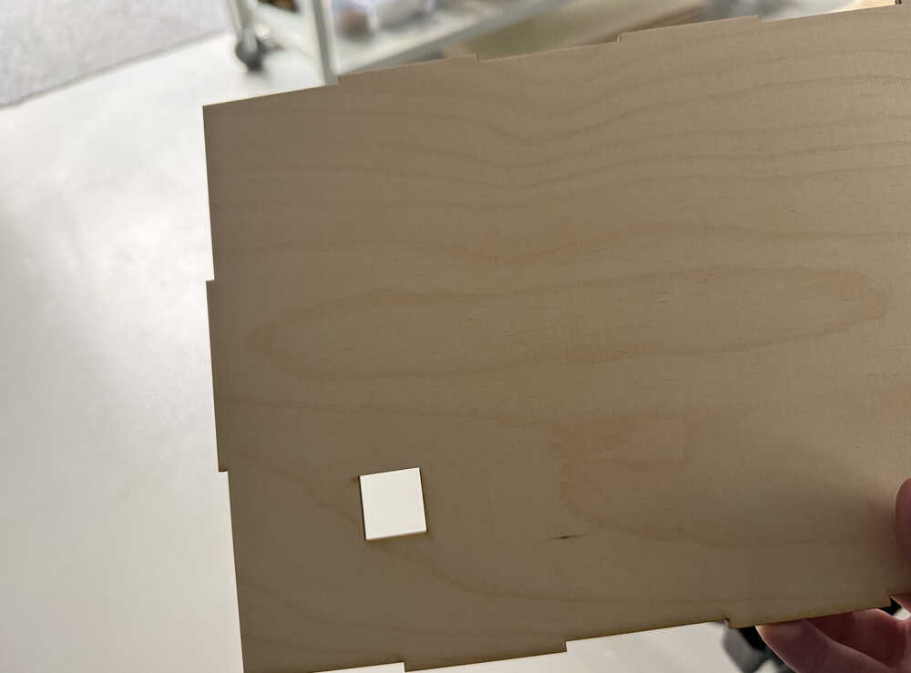
I cut 10 1cm squares to test the kerf of the machine.
The kerf is 1.93 / 20 = 0.0965mm.
I updated the parts and was printing them again. However, just as I was about to print the ones with the female points, I realized that I set the kerf wrong for these specific parts (I accidentally wrote "+kerf" instead of "-kerf" to these parts). So I fixed the design. However, when I tried to put the parts together, they didn't stick to each other.
I started to test with smaller pieces:
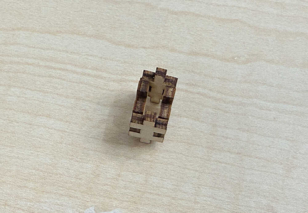
These fit perfectly.
I started to think of the differences of my design from Mehmet's design. I realized that I used points and edited them separately while he used boolean rectangles. Then I realized that, when I was adding kerf to Mehmet's design, I didn't do it properly. Since, when I was adding kerf to the rectangles, I wrote "+kerf" to the parameter of the part, the height and width of the rectangles only expanded by half the amount of kerf I wanted it to have. I had to write "+ 2 * kerf" to the height part (and the width part) to give both the top and the bottom (and the sides) an increase in length equal to the kerf.
I changed Mehmet's design while taking this into account and printed the parts again; however, it didn't work this time as well. That's why I decided to just design another one.
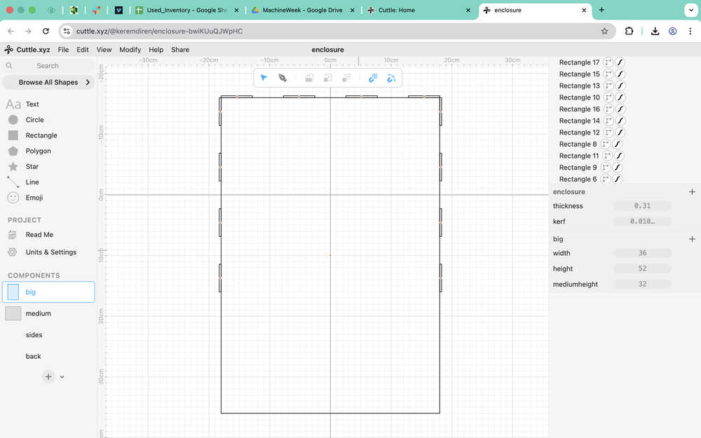
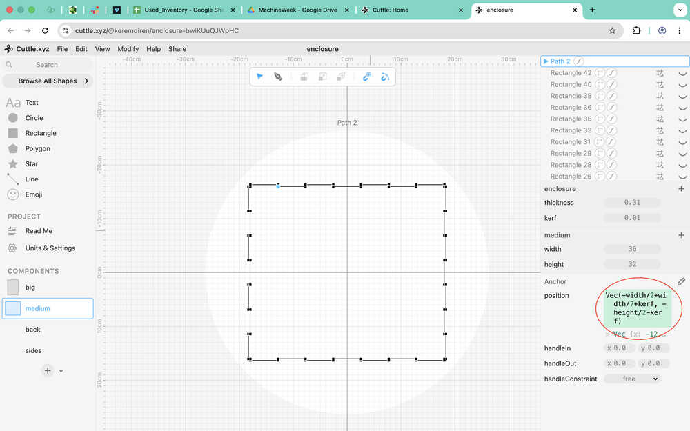
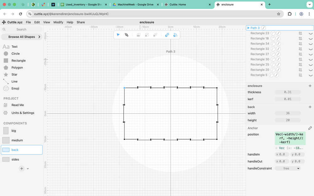
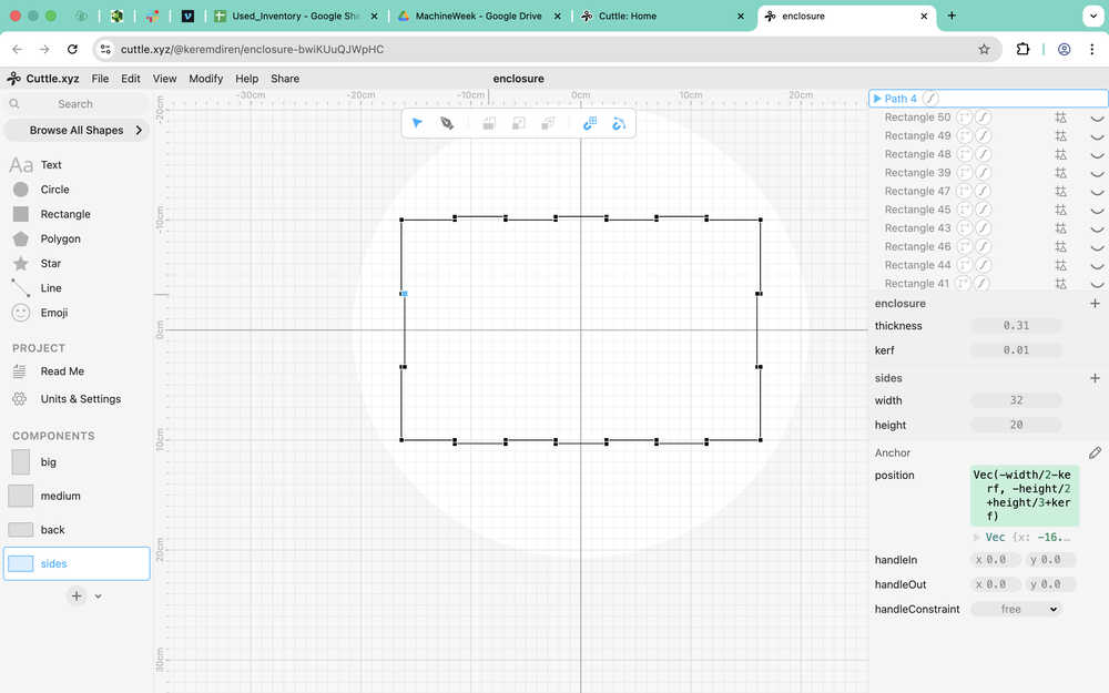
I created some components and parameters. Some of the parameters I've created are global, some are private to the components themselves.
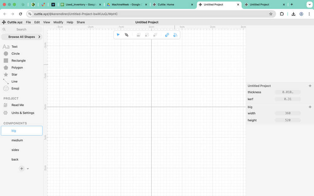
As you can see, I decided to add a total of 3 intersections.
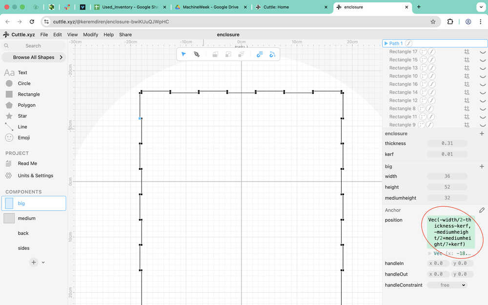
I used the pen and added the parameters to the design.
I did it for the other components as well:
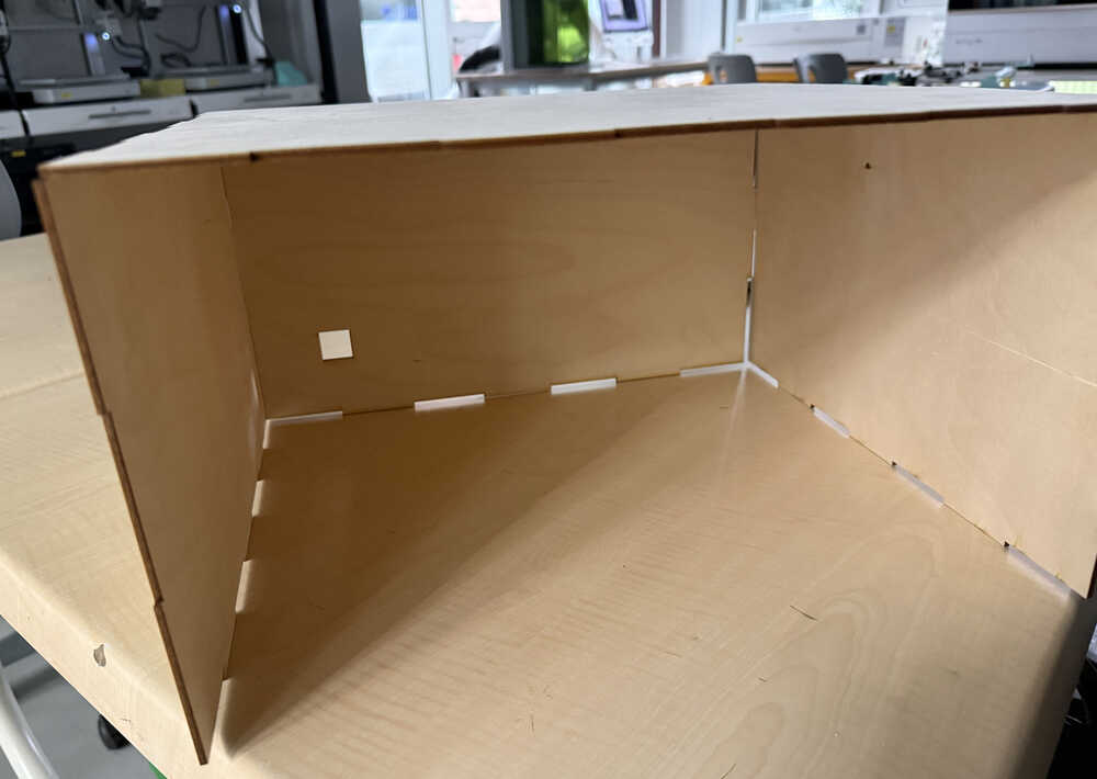
I wanted to test the new design so I only printed some of the pieces. The pieces can finally stay together!
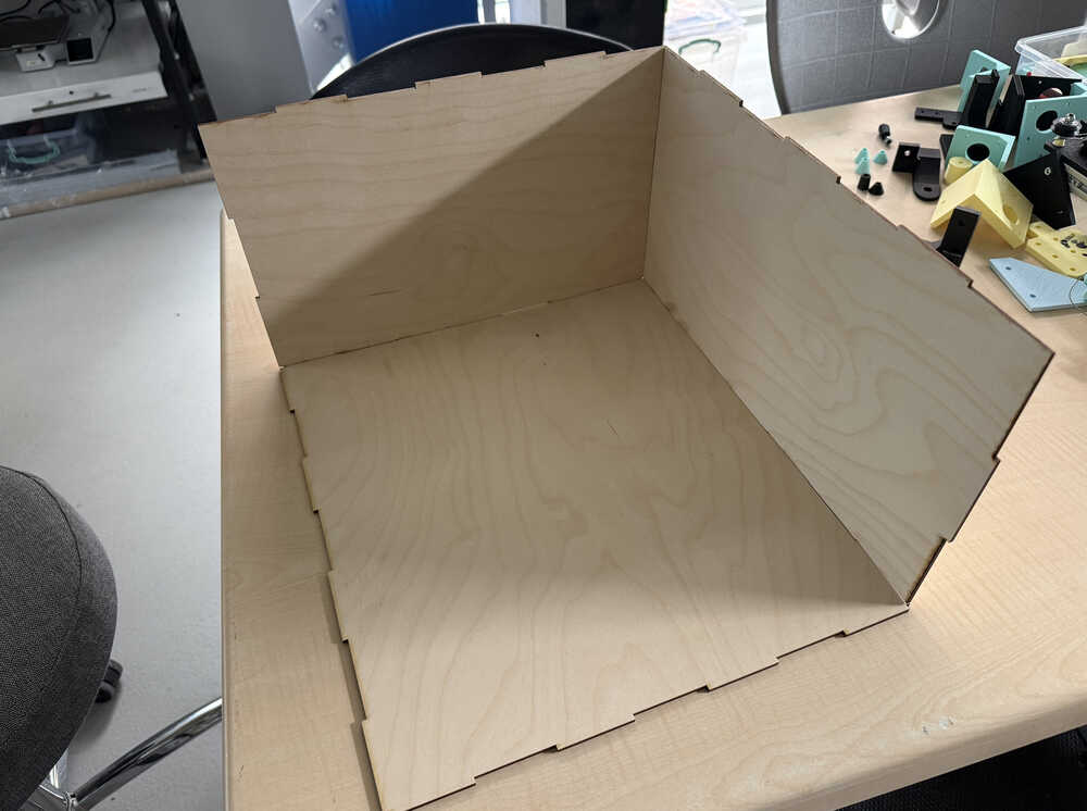
I opened a cable hole in the back of the enclosure.
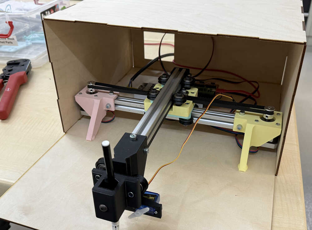
The top part of the enclosure is done.
We printed the bottom part and finished the enclosure!
Sticker
Final Version
Process
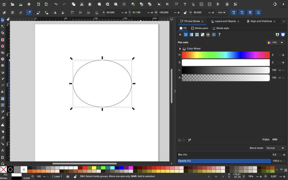
I first started by creating a 100mm by 80mm circle, which will be the sticker's size.
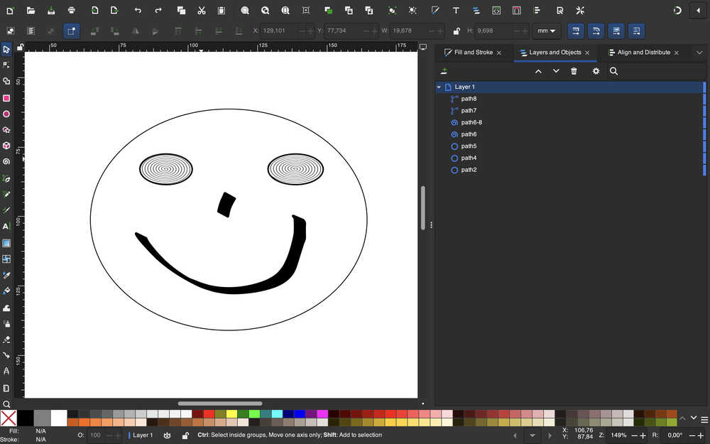
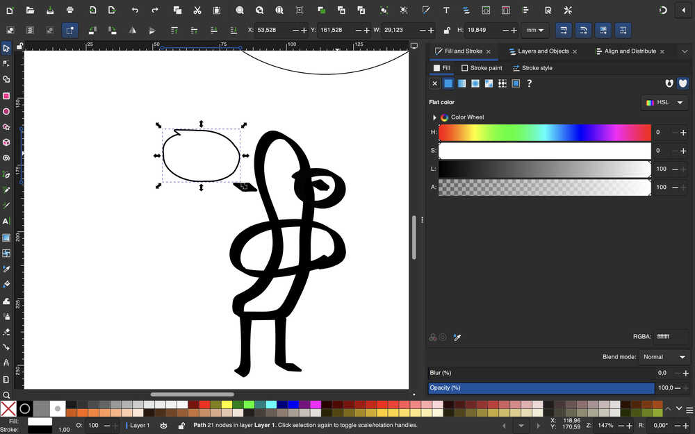
I made the face. The first sticker is done. I used the spiral tool and the ellipse tool to make the eyes. I used the calligraphy tool to create the nose and mouth.
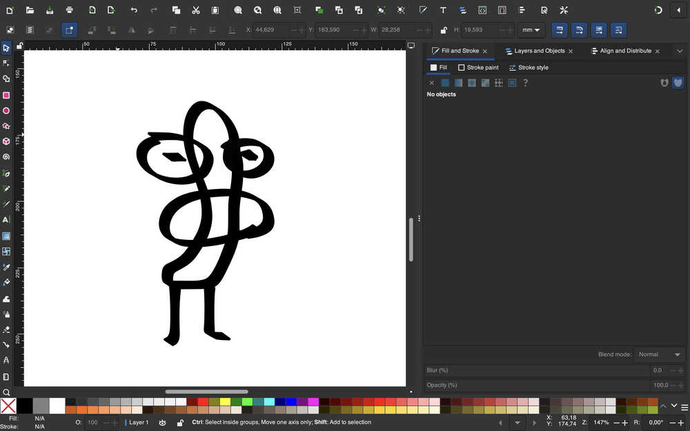
For my second sticker, I drew a weird character using the calligraphy tool.
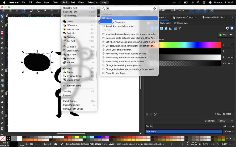
Then, I used union on it with an ordinary circle.
It turned completely black.
Then, I filled the inside with white.
Then, I increased the stroke width.
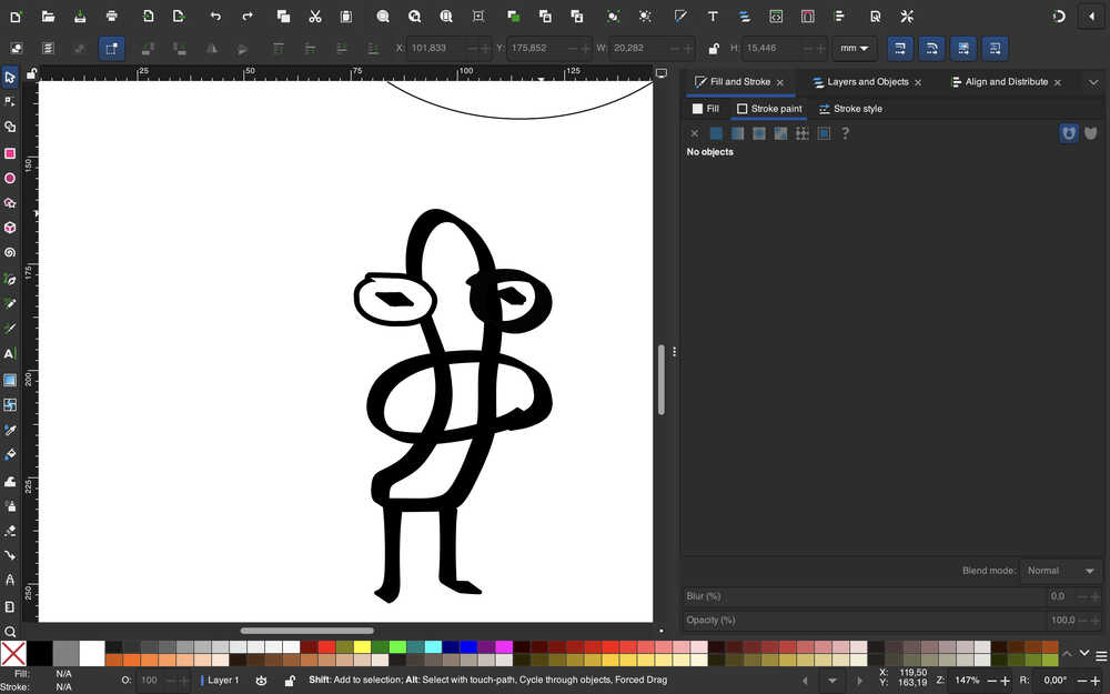
I repeated this procedure for the other eye as well.
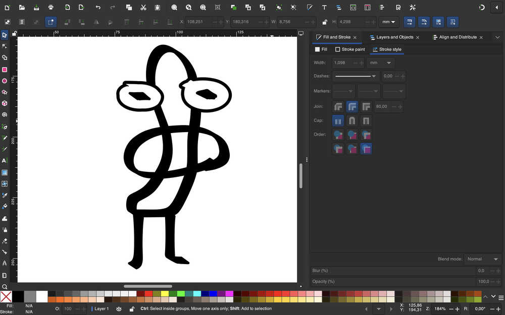
The second sticker is done.
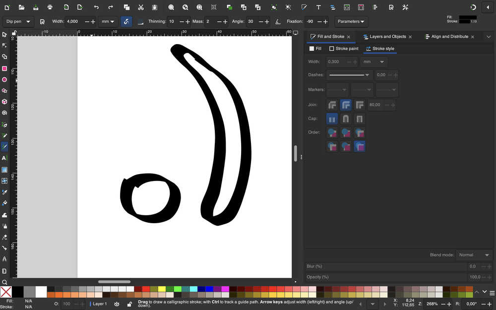
Now, I'll create the third sticker.
I first drew a " .) ".
I gave them faces.
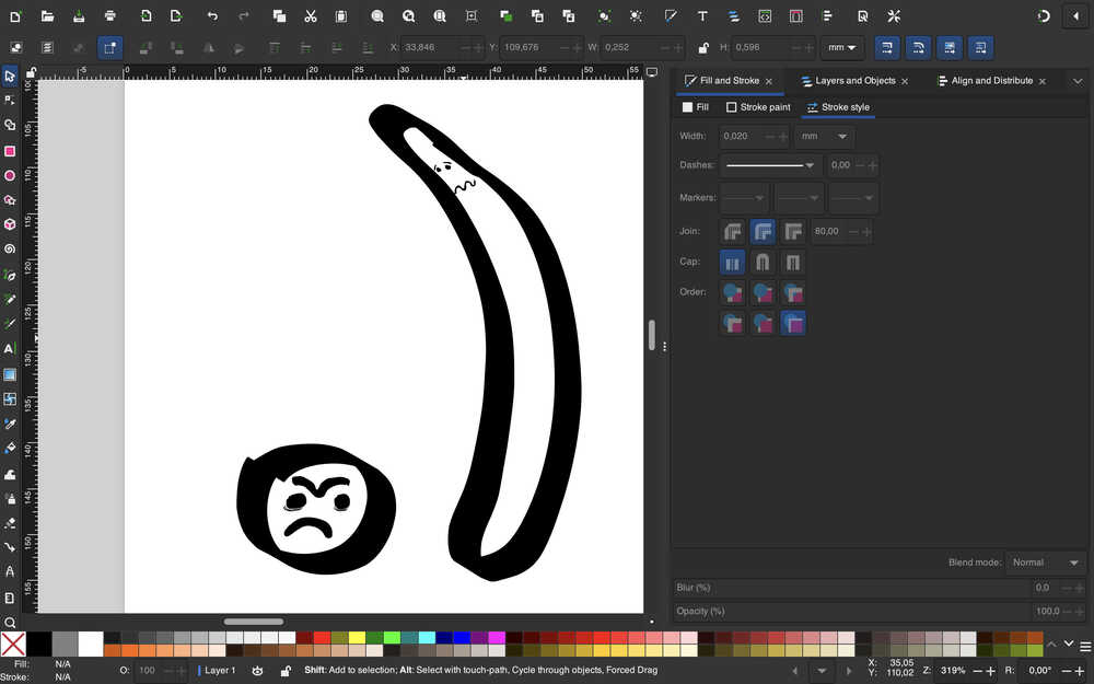
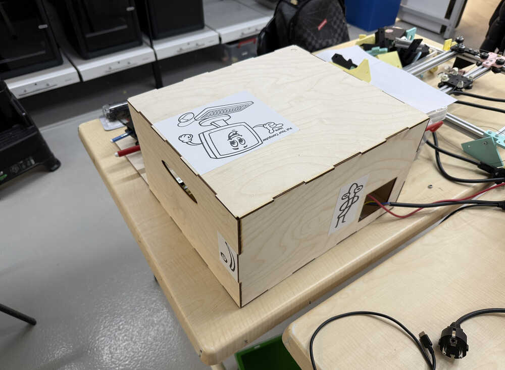
These stickers are all done.
I grouped them accordingly.
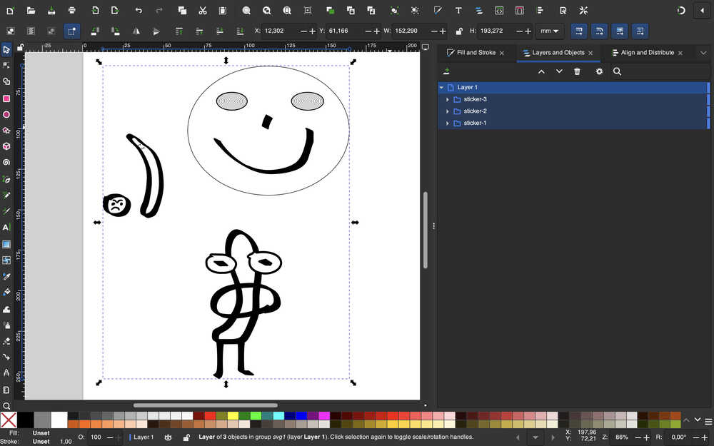
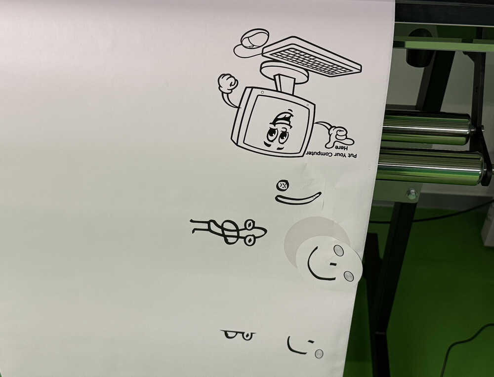
I don't know what the others'll create or whether they'll create some stickers at all, but, either way, the plotting robot needs some goofiness, which is why I drew these goofy stickers.
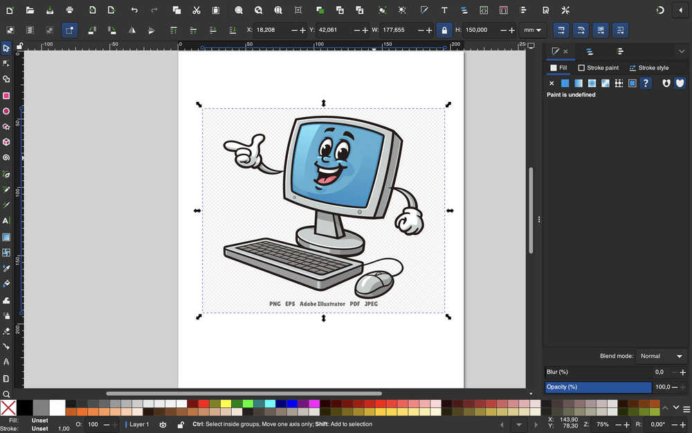
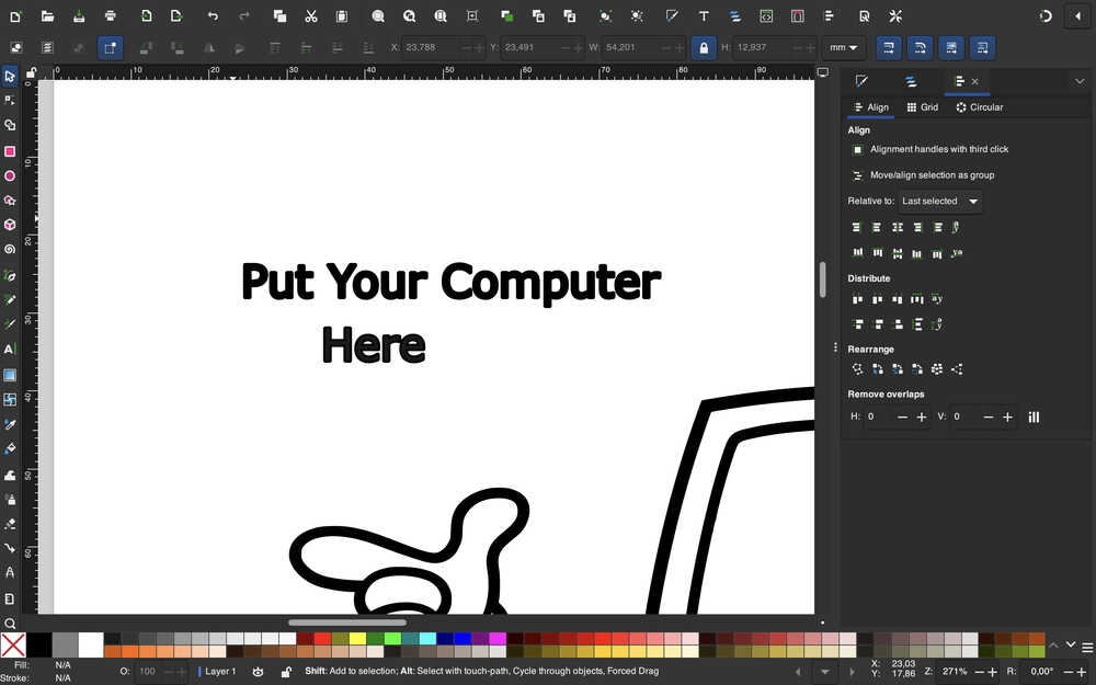
Now, I'll create a sticker to indicate that you can put your computer on the enclosure.
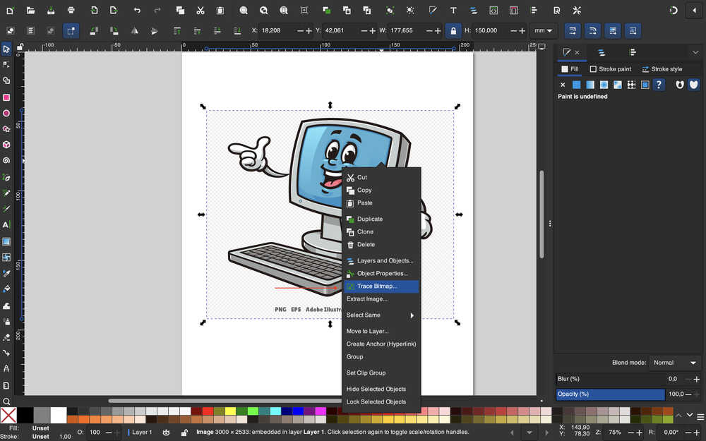
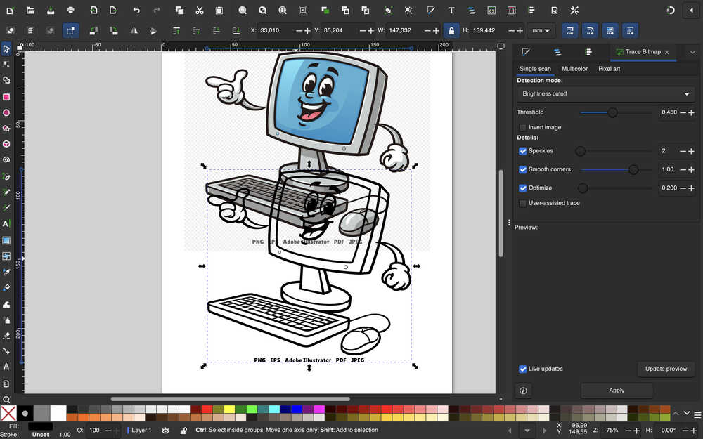
I first imported this image and set its size to 150mm by 177mm.
Then, I right-clicked and selected "Trace Bitmap".
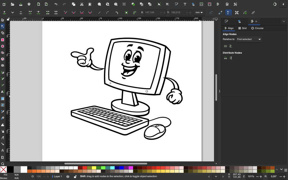
I clicked "Apply" and ended up with this:
I deleted the text.
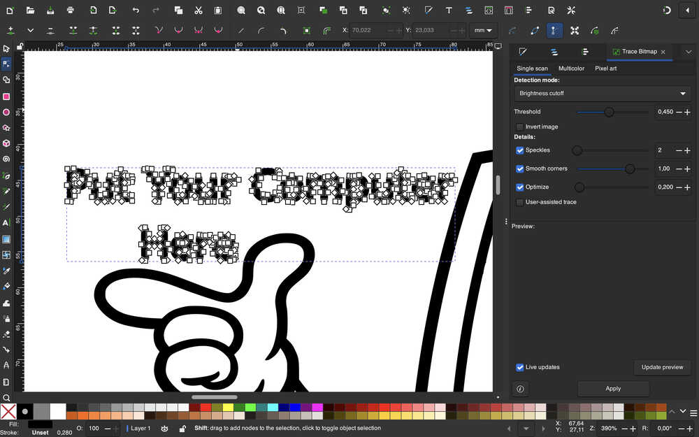
I created a text and took a photo of it. For some reason, text doesn't get generated in the Cricut website, so I'll do the same I did to the computer image.
The text is ready:
This sticker is now finished.
Since I didn't know the password to the Cricut account, I asked for help from my friend Emre Dayangaç (also in Fab Academy); he helped me with using the BN-20A machine instead.
They're out.
As you can see, there was a problem when printing at first. For some reason, the machine stopped halfway; however, after starting the machine again, it was solved.
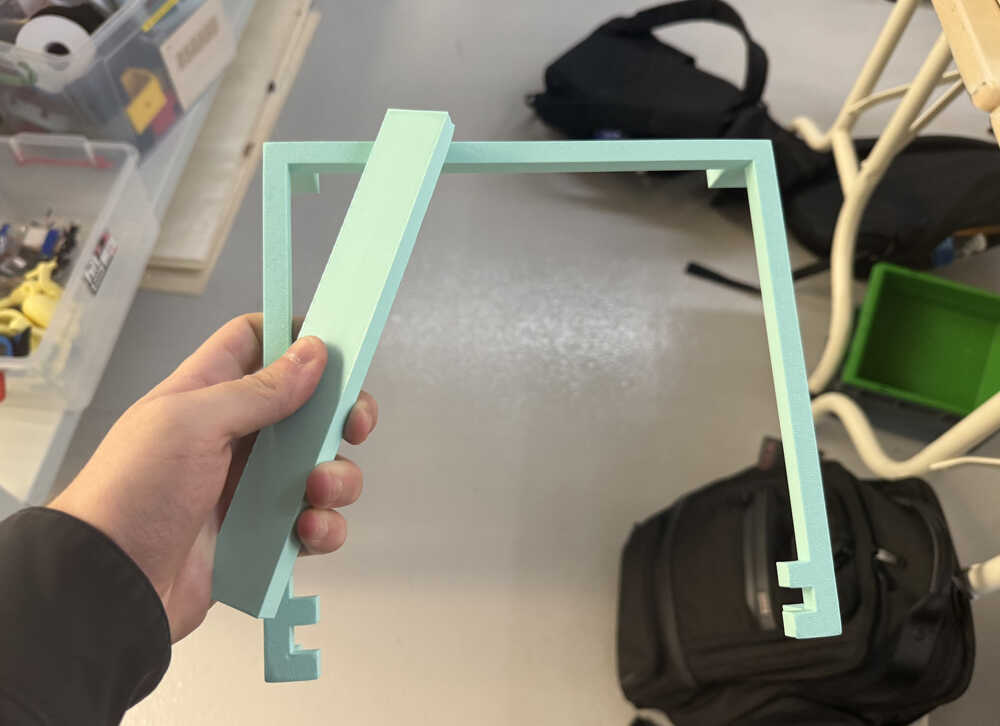
Paper Preparer
Idea
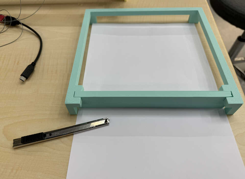
I want to create something so that people can quickly (and with little effort) cut 21cm by 21cm paper, which is needed for our plotter machine.
Final Version
Process
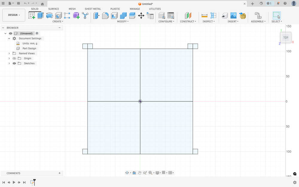
Sketch:
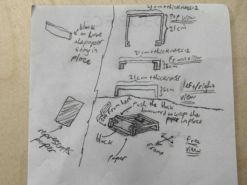
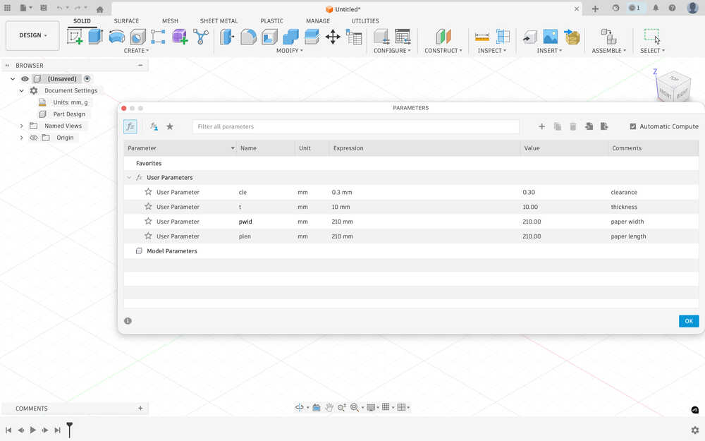
I first set the parameters.
I sketched the four legs of the paper preparer. The four big rectangles represent the desired paper (and, as such, have the parameters pwid and plen in their size equation).
I added the h parameter that I'll use to define the height of the empty space. I made this parameter 2cm less than what I wrote into the sketch.
I extruded the sketch by h.
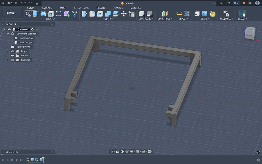
I extruded the connection between the legs by using the t, plen, and pwid parameters.
The block (used h, pwid, t, and cle).
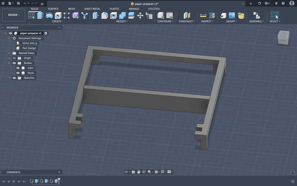
The design is finished.
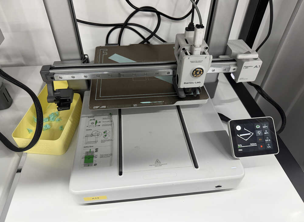
I started the 3D printer.
The thing is out.
Usage video:
Files
Link to the design.
The files.