Week 9, Input Devices
Table of Contents
- Overview
- Resources
- Group Assignment
- PCB Design
- Milling/Soldering
- Coding/Testing
- Files
Overview
This week, I tested some inputs. The ultrasonic sensor input was the most important among these since I wanted to test it for my final project and decided not to use it. I'll probably use VL53L1X.
Resources
- ChatGPT: I want to connect a color sensor, an Ultrasonic sensor, and a Button to xiao_esp32. How many pins do I need exactly? What inputs do these sensors require?
- I used Kicad.
- I used Mods.
- I used SRM-20.
- I used Arduino IDE.
- I used ChatGPT to help with writing code.
Group Assignment
Here is the group assignment.
PCB Design
Idea
I want to create a PCB with 4 inputs. The button input will be used to light an LED while the other two will have something to do with the program I'll write.
Final Version
Process
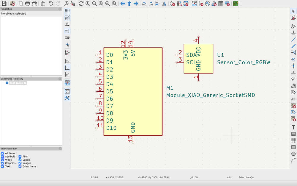
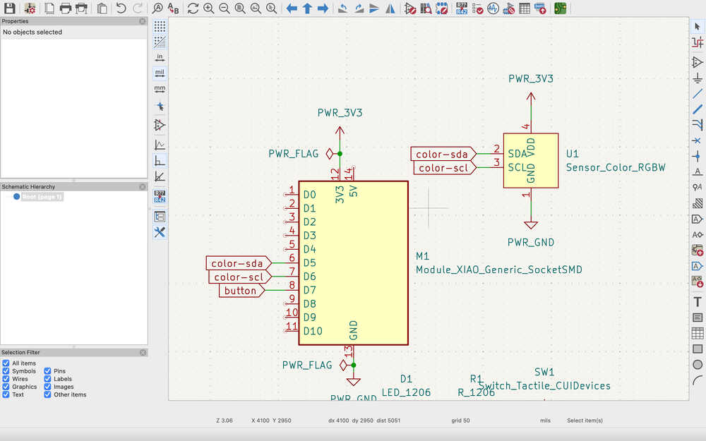
I imported the two main parts I'll stick onto the PCB.
I also added these to the design.
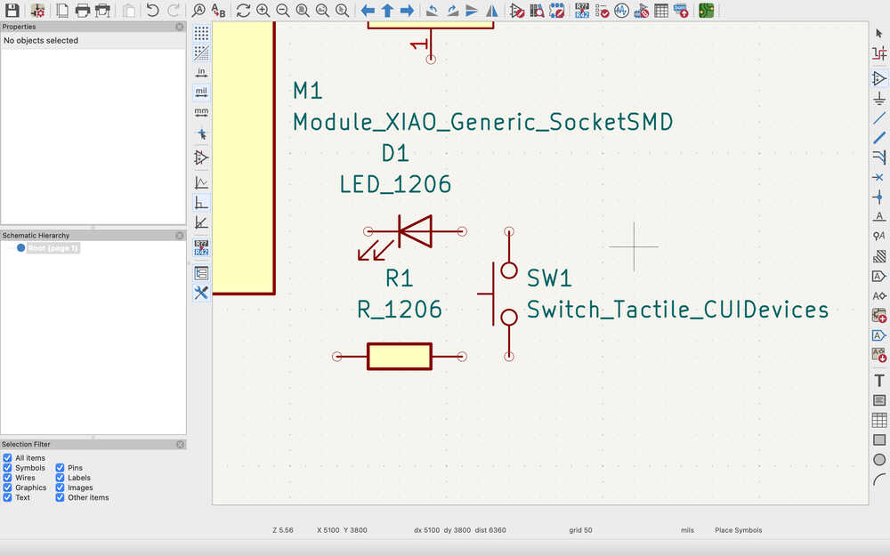
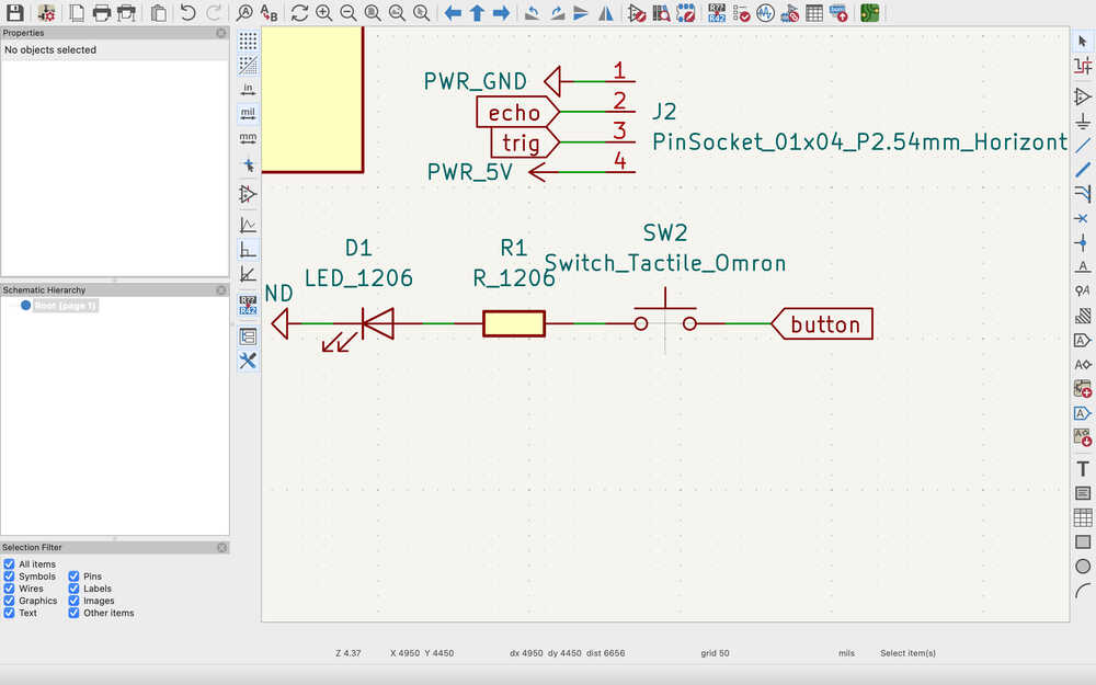
I first connected the pins of the button.
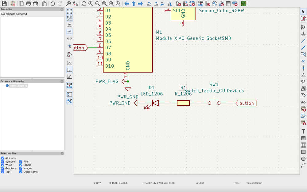
The resistor will be about 300 ohms.
Then, I connected the pins of the color sensor.
Finally, I connected the pins of the ultrasonic sensor. I used pin sockets to represent the ultrasonic sensor.
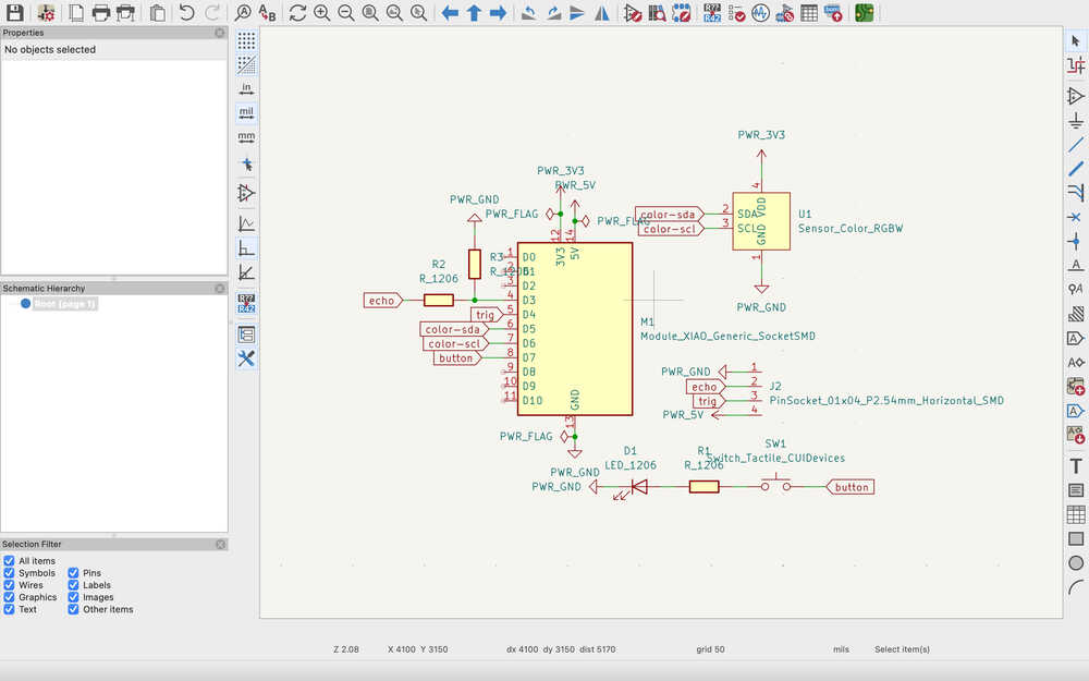
The resistors will be 2k and 3.5k ohms (or at least something close to these values).
I put no connection flags onto the pins I'll not use.
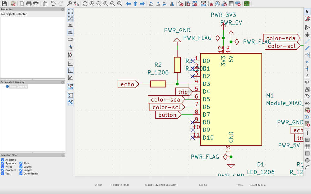
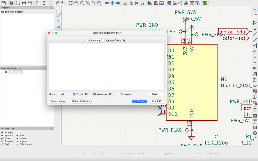
After running the ERC and seeing as there's no problem, I continued to the PCB layout part.
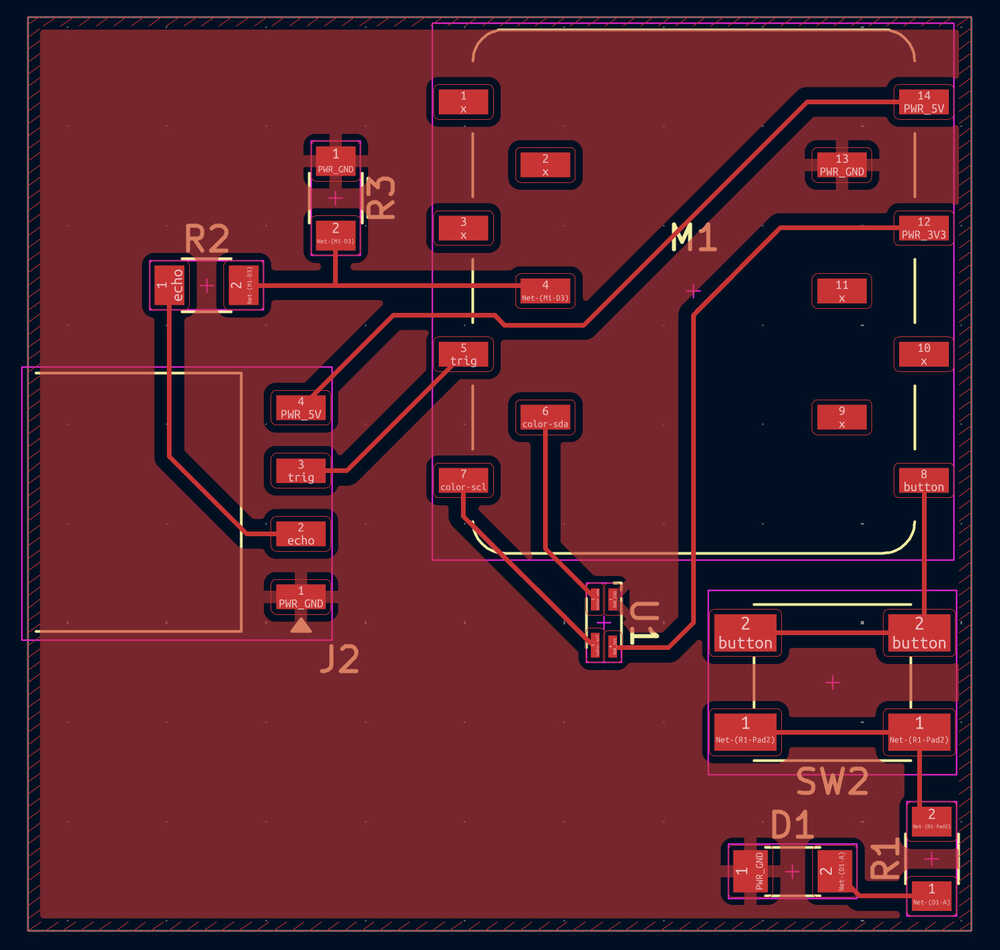
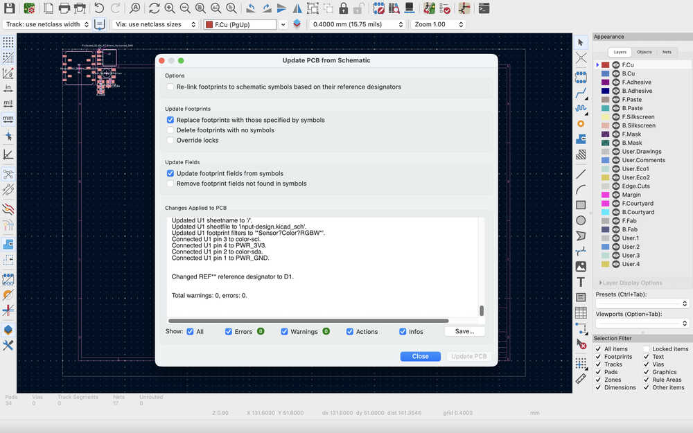
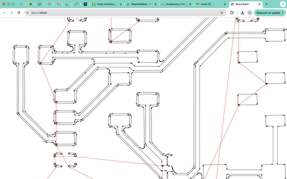
I updated the PCB layout depending on the design.
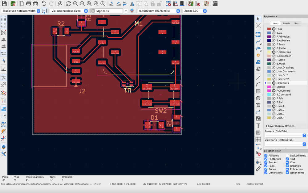
After I went to the lab, I realized that I got the wrong button, so I changed it to this:
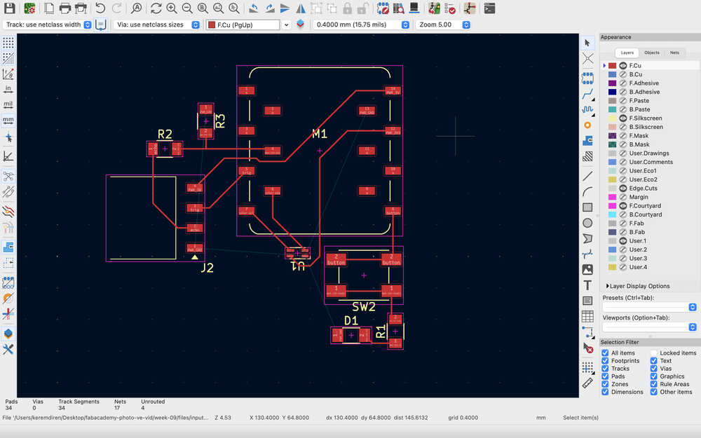
I also updated the layout accordingly.
I connected the cables.
I set the boundaries.
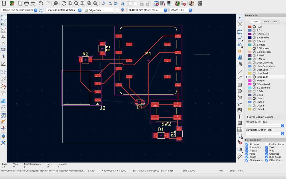
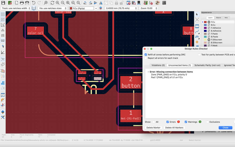
I filled the copper layer and ran a DRC but there was an error. The edge was too close to some components.
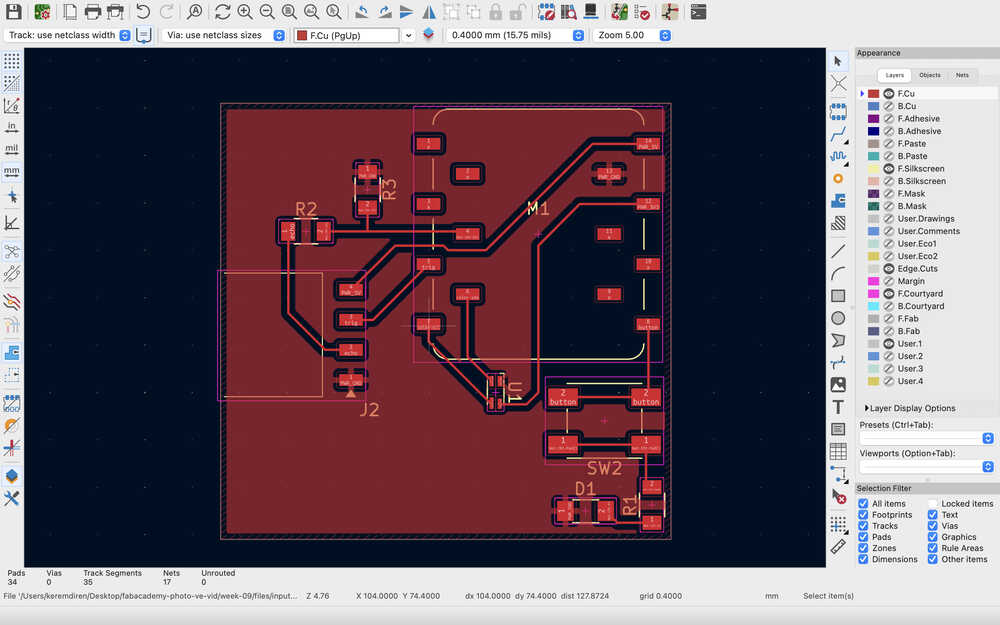
I fixed the issue; however, this time I realized that one of the edges weren't connected.
It's complete.
Milling/Soldering
Final Version
Process
I plotted the parts:
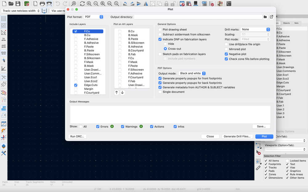
I realized this when I was doing this PCB but I had to leave all check marks empty for the "plot on all layers" section since it causes unnecessary stuff to happen.
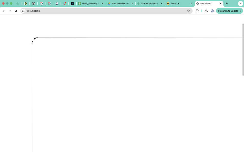
I finished the Inkscape of the Edge.Cuts file.
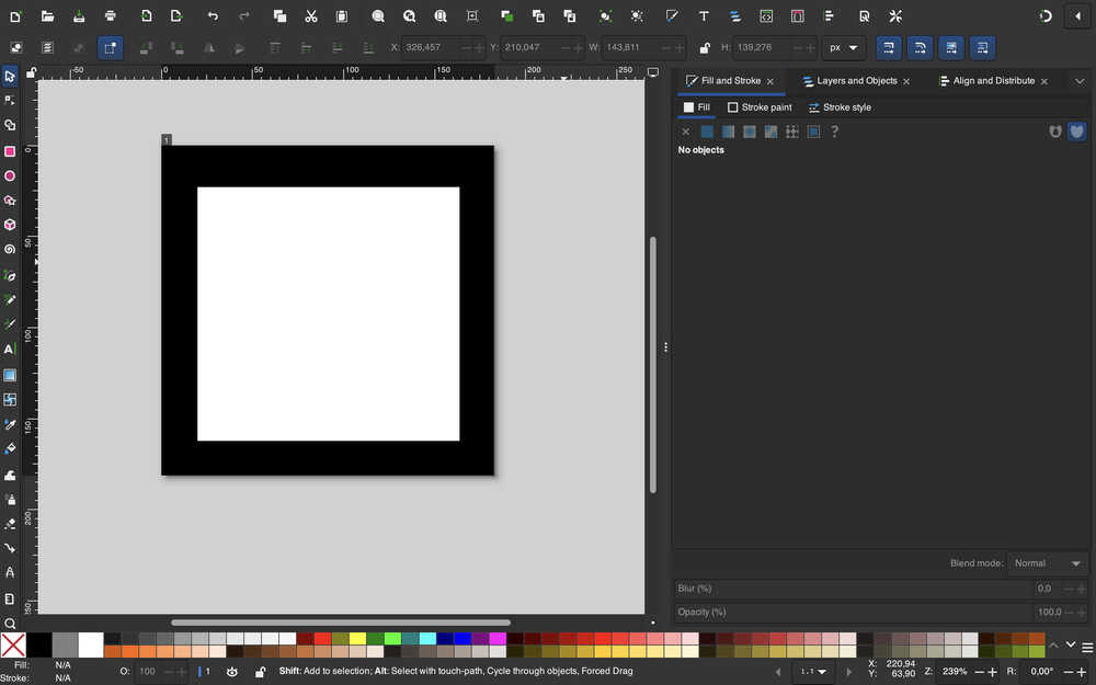
I finished the Inkscape of the F.Cu file.
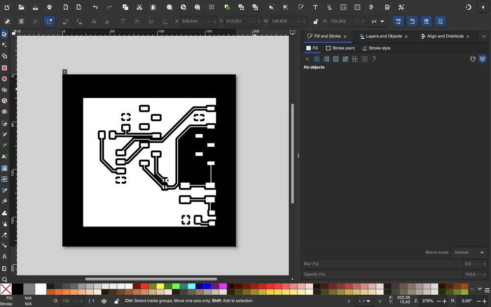
While doing the Mods website, I should mention that I learned about what caused the tip to leave a line on my old PCB. Apparently, because the home in the photo you see below was set to 0 height, the tip went through the PCB to get to its home position. It didn't bother with jog height since the PCB was already milled.
The rml file for F.Cu is ready.
The rml file for Edge.Cuts is ready.
I sent the files to the milling computer.
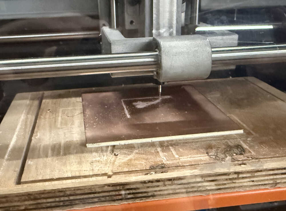
Milling F.Cu:
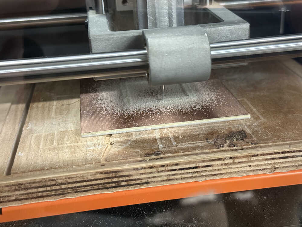
Milling Edge.Cuts:
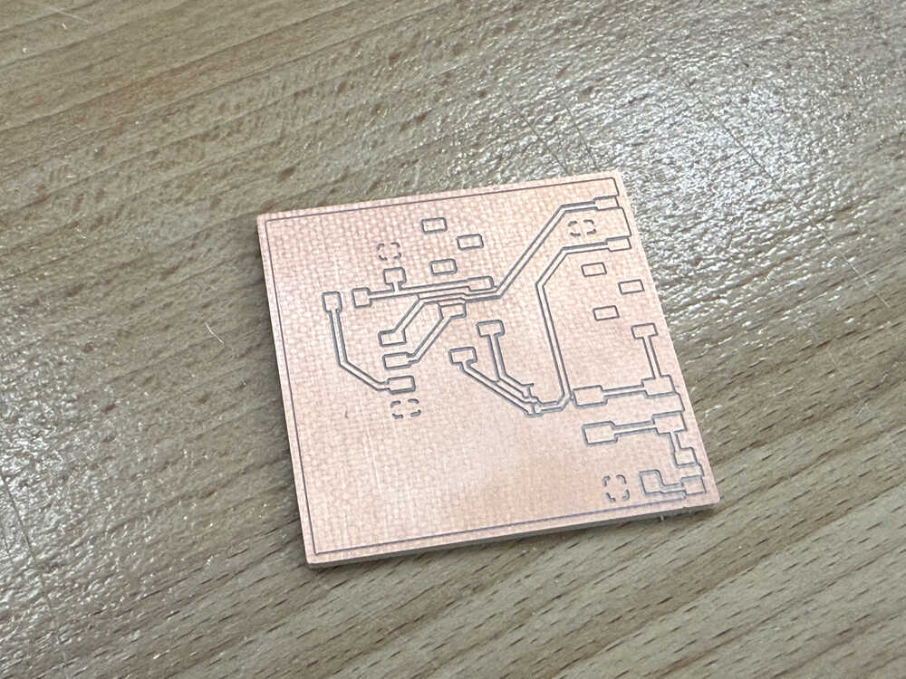
The PCB is out!
These are the parts I'll solder.
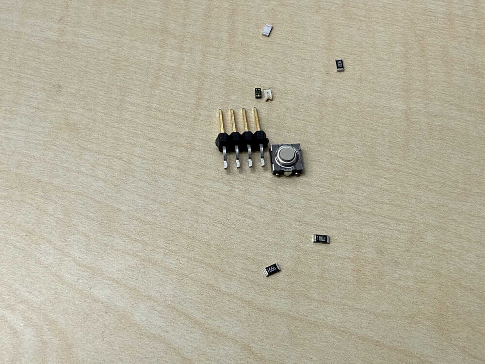
Since I couldn't find resistors with correct resistance, I'll be using resistors with 100 ohm, 5k ohm, and 10k ohm resistances. I'll use two 100 ohm resistors since 100 ohms would be too low by itself. Also, I'll need to use horizontal pin headers instead of horizontal pin sockets since I couldn't find any horizontal pin sockets.
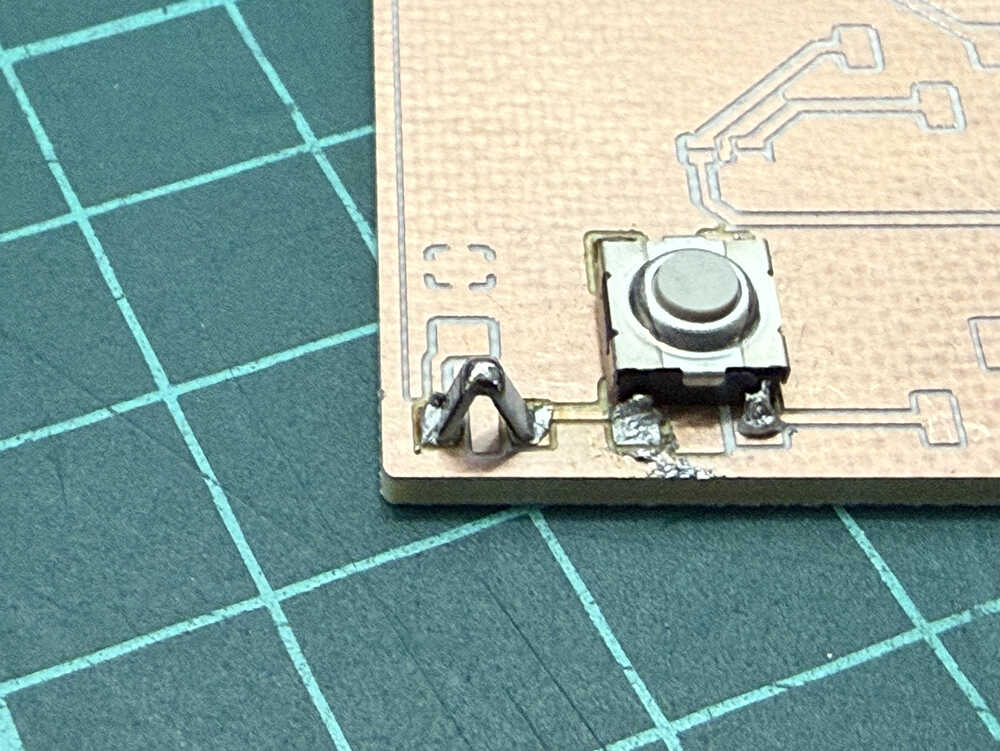
This is how I soldered the two 100 ohm resistors:
Also, just as I was about to solder the 4x pin headers, I though "does this lab REALLY not have any horizontal pin sockets?" and begun my search. I was able to find a 6x one, so I cut off two of them and now had a 4x horizontal pin socket.
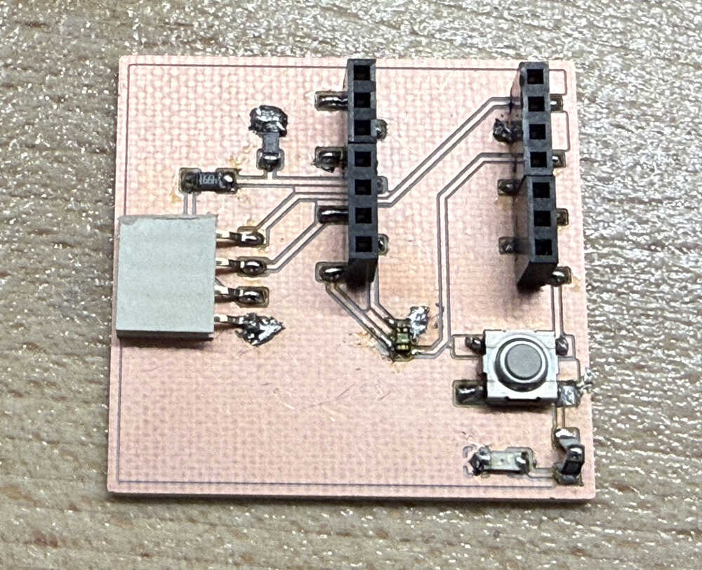
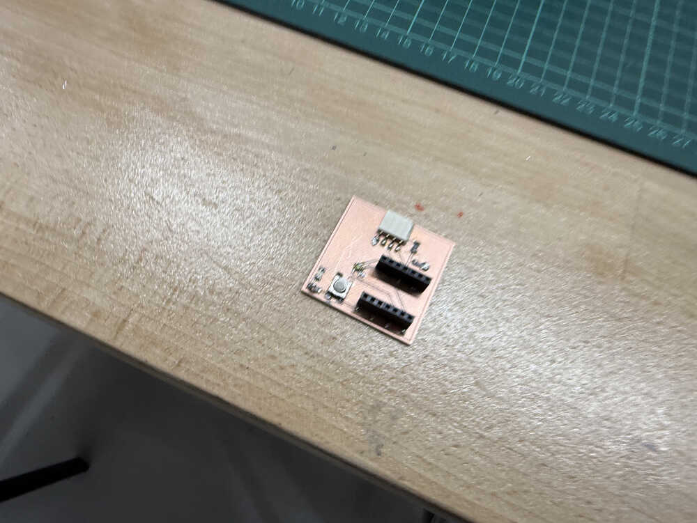
Finished soldering.
Coding/Testing
Idea
I just want to test whether these inputs work or not. Currently, the most important thing is making the HC-SR04 since I want to decide whether I'll use it for my final project or not.
Process
I wrote this code with help from ChatGPT.

When starting, I got an error because I wrote Pin instead of pinMode. After fixing it, I tested the code.
The distance sensor.
The button-led.
Files
The files can be found here.