Week 8, Electronics Production
Table of Contents
- Overview
- Resources
- Group Assignment
- Preparing Files
- Milling
- Soldering
- Files
Overview
This week, I produced the PCB I designed in a previous week. I used Kicad, Inkscape, and the Mods website to get the milling file. I used SRM-20 to mill my PCB. Then, I soldered my PCB.
Resources
- I used the Mods website to generate my milling files.
- I used Inkscape to get help with generating my milling files.
- I used Kicad for my design.
Group Assignment
This is the group assignment.
Preparing Files
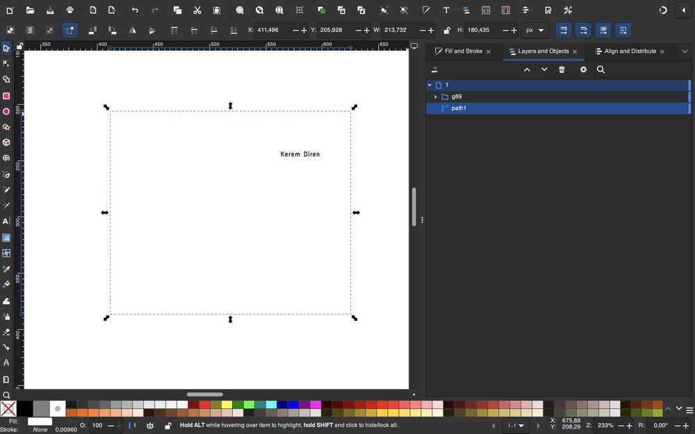
Photo
Process
Inkscape
First, I opened my design files.
I clicked the "Plot" on the top right corner of my screen. Then, I selected the pdf format for the file type. Then, I turned the "negative plot" selection on. Finally, I selected F.Cu, Edge.Cuts, and User.1 for "Include Layers", and I selected Edge.Cuts for "Plot on All Layers".
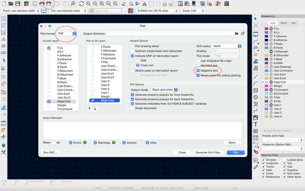
Then, I clicked the "Plot" button.
Now, I'll edit these files from Inkscape and get them ready to use in the Mods website, which is where I'll use to generate the rml files for milling.
I imported the Edge.Cuts file to Inkscape.
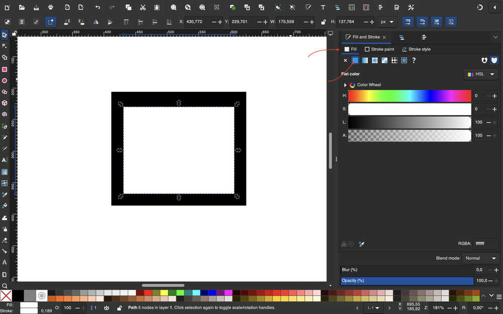
Then, I filled the inside of the white rectangle with white.
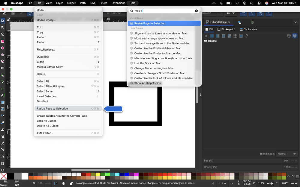
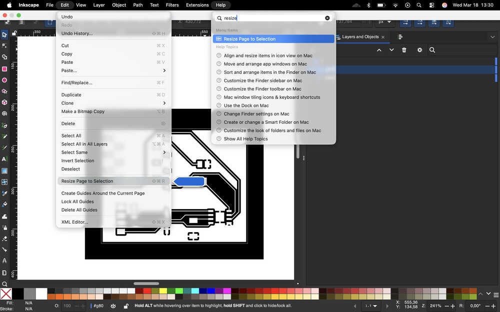
I selected the "Resize Page to Selection" button.
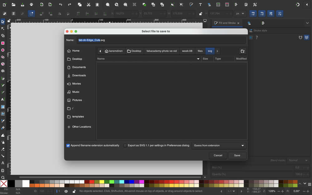
Then, I saved the file as an SVG.
I imported the F.Cu file.
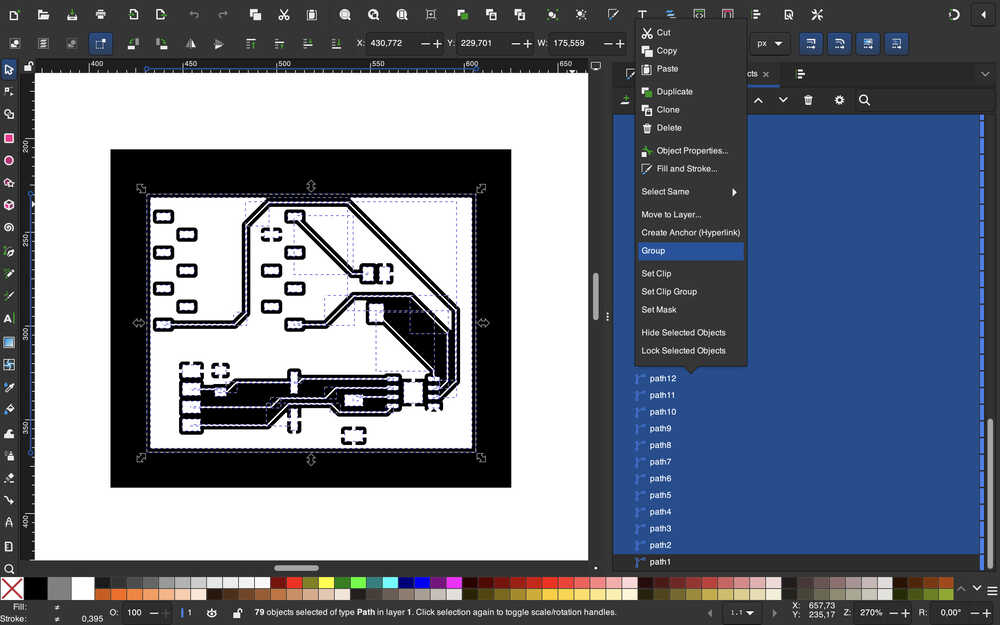
Then, I grouped everything except the outer, black rectangle.
I used "Resize Page to Selection" and saved the file as an SVG.
I imported the User.1 file to Inkscape.
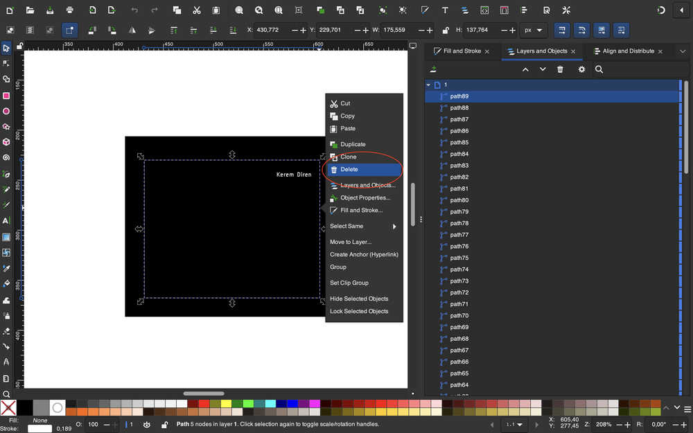
This time, I deleted the Edge.Cuts layer in the file.
I grouped everything except the outer, black rectangle. Then, I changed the color of the outer rectangle to white. Then, I changed the text's color to black.
I used "Resize Page to Selection". Then, I saved the file as an SVG.
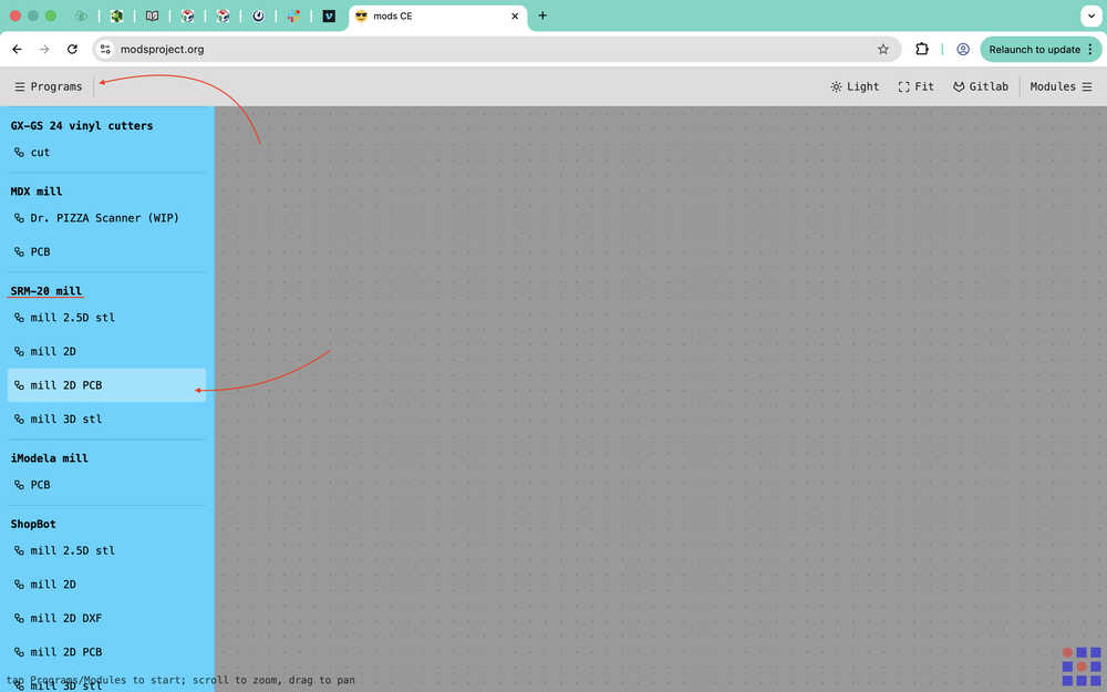
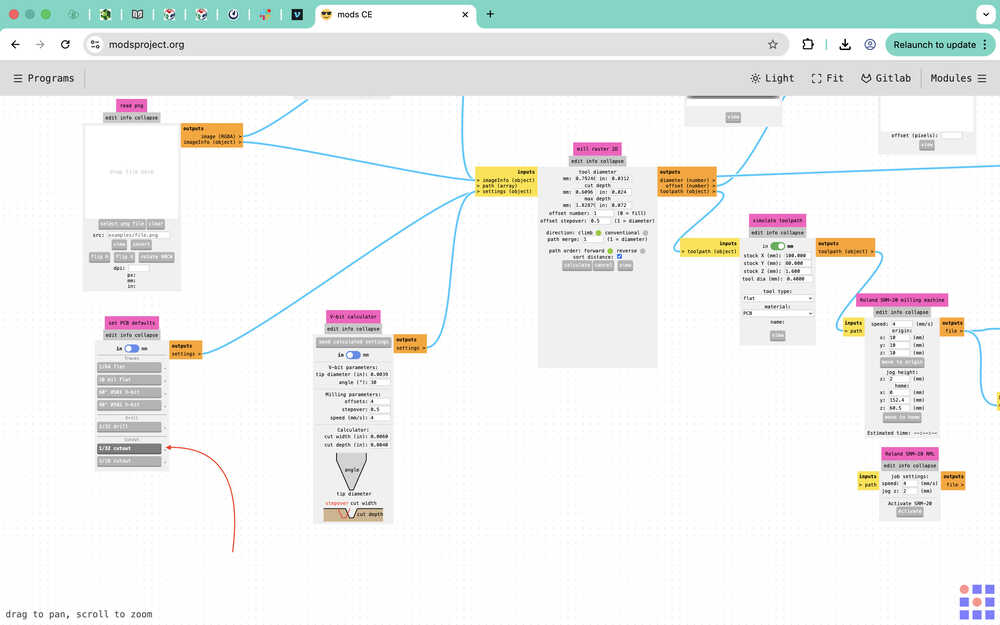
Mods
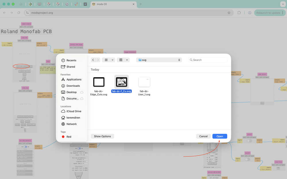
I opened the mods website. Then, I opened the section to create my desired rml files.
I selected the "select SVG file" button and imported my F.Cu layer SVG file.
From the "set PCB defaults" section, I selected the "1/64 flat" button.
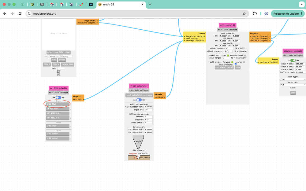
I set the following settings to the V-bit calculator tab. Don't forget that you need to set the parameters of your V-bit depending on what you own.
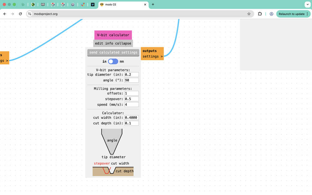
Then, I clicked the "send calculated settings" button.
I entered the following settings into the "mill raster 2D" section.
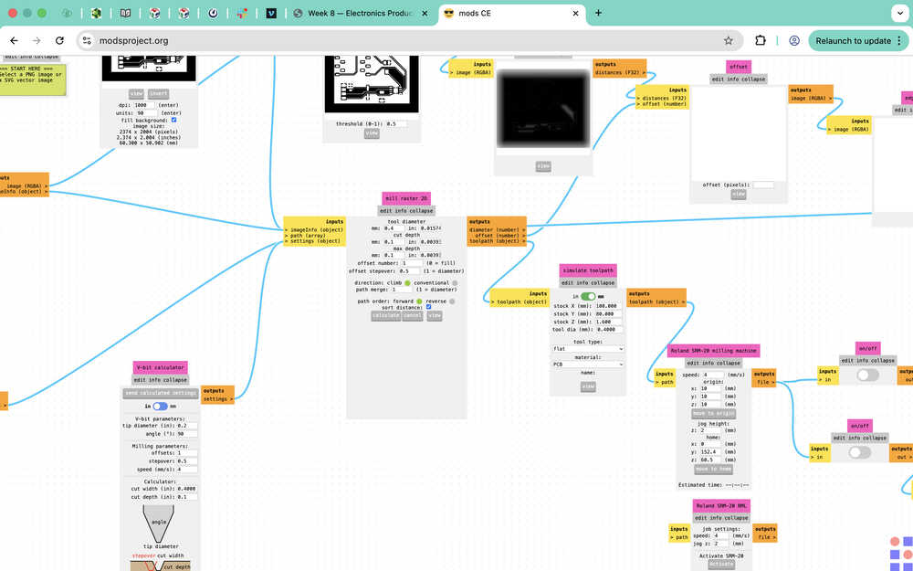
I edited the circled parts as shown.
I clicked "calculate" under "mill raster 2D".
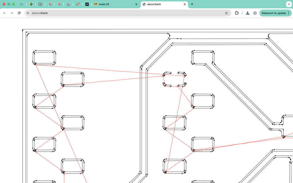
I repeated the exact same procedure for the User.1 layer; however, probably because the text's punto was too small, no path was generated.
I was able to generate a path after decreasing the "tool diameter" parameter to 0.1. Because the diameter is not actually 0.1, the text will be really hard to read after it's milled; however, this is better than having no text at all. It is important to give the text big enough so that the tool can actually cut it.
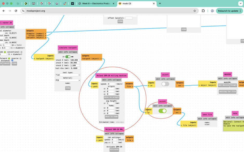
Finally, I imported the Edge.Cuts file. I selected the "1/32 cutout" button for "set PCB defaults".
I set the settings of the "mill raster 2D" part as the following.
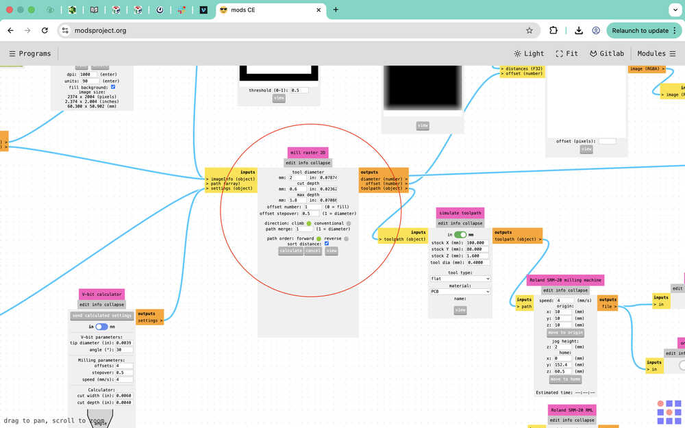
I set this part as the following.
I clicked "calculate".
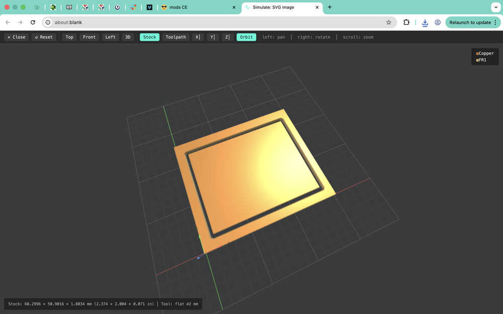
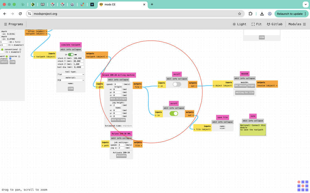
Milling
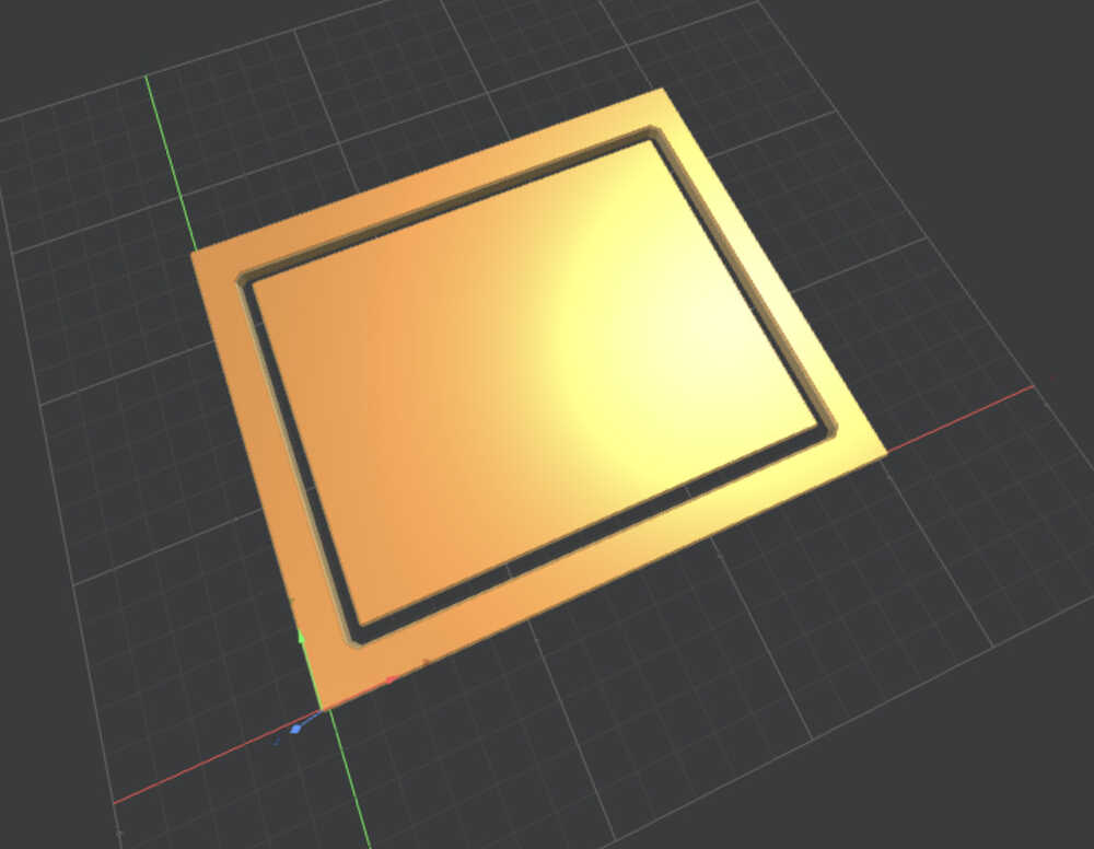
Final Version
Process
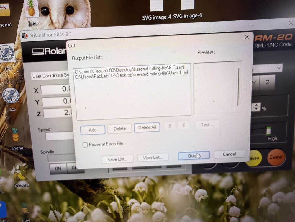
I sent the files to the printing computer.
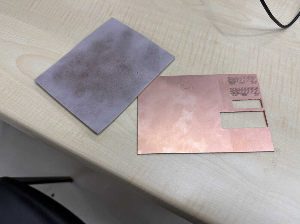
I found a half-used copper clad and used sandpaper on it.
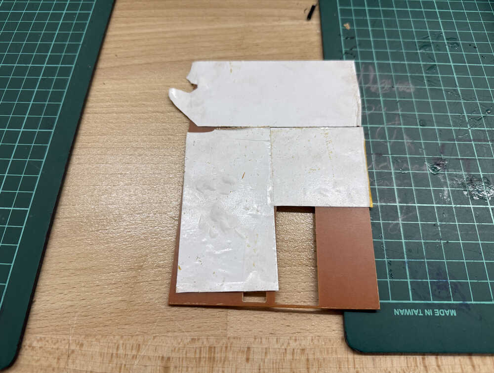
I put two-sided tape to the pack of the clad.
I put the clad into the machine.
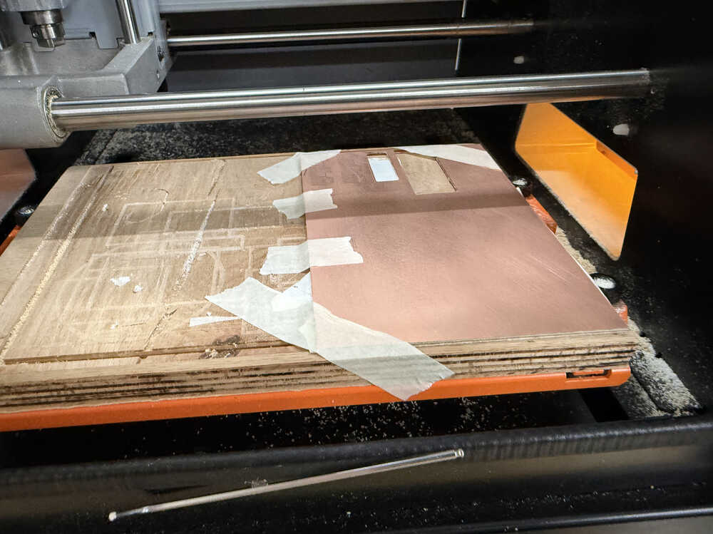
I put the first bit in.
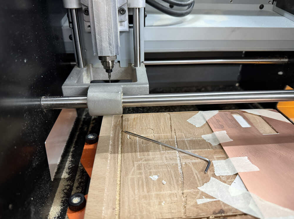
I set the location to just above the location I want the PCB to be milled.
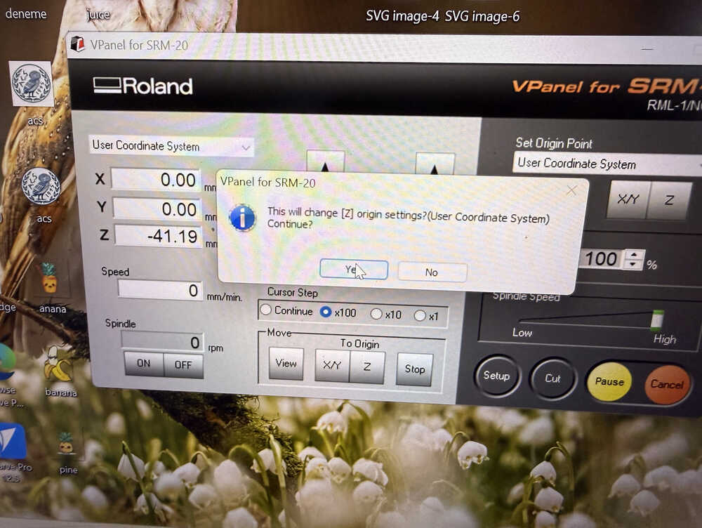
I let the bit loose and let it touch the clad. Then, I fastened it again.
I put the bit 2mm above the starting location.
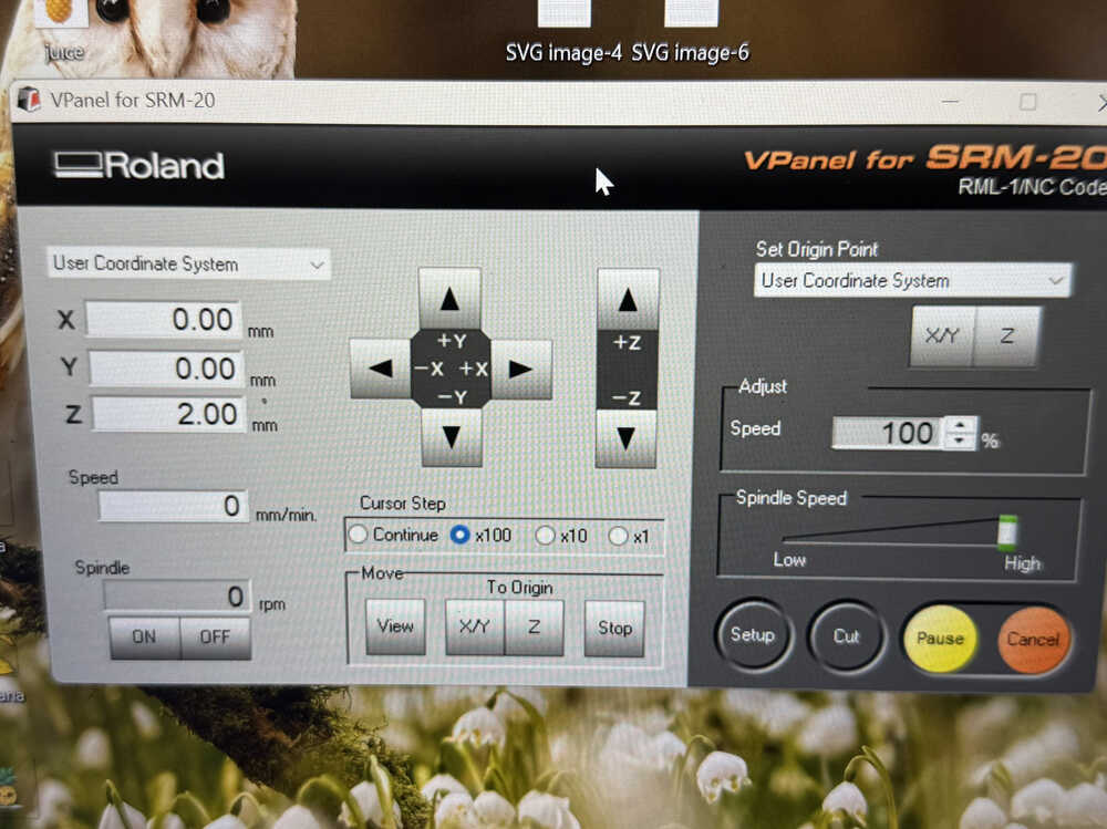
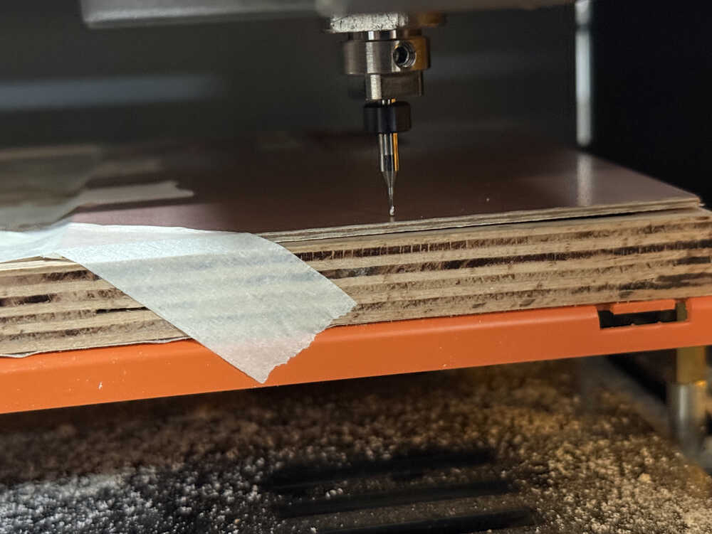
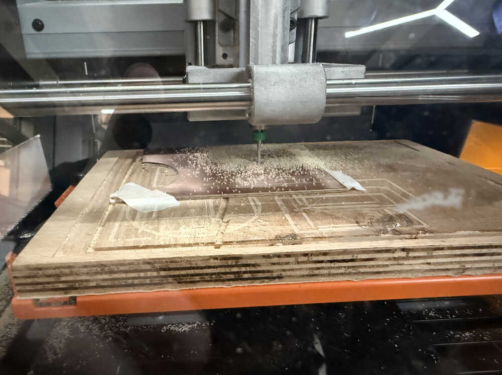
I started the process.
Because of the uneven height, the machine didn't cut. That's why I started the machine at a different location. However, that didn't work. In the end, the clad was pretty messed up, which is why I decided to use another one.
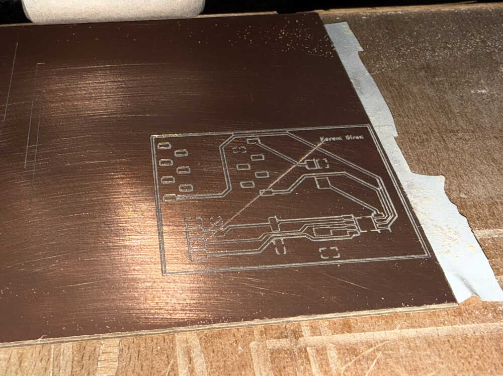
It's working:
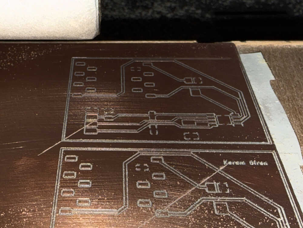
When the machine started the User.1 layer, it went through the paths, which cut their connection. That's why I decided not to do the User.1 layer.
After checking with a multimeter, I learned that everything's fine except 1 connection, which I can fix pretty easily by myself. That's why I decided to continue with the Edge.Cuts file.
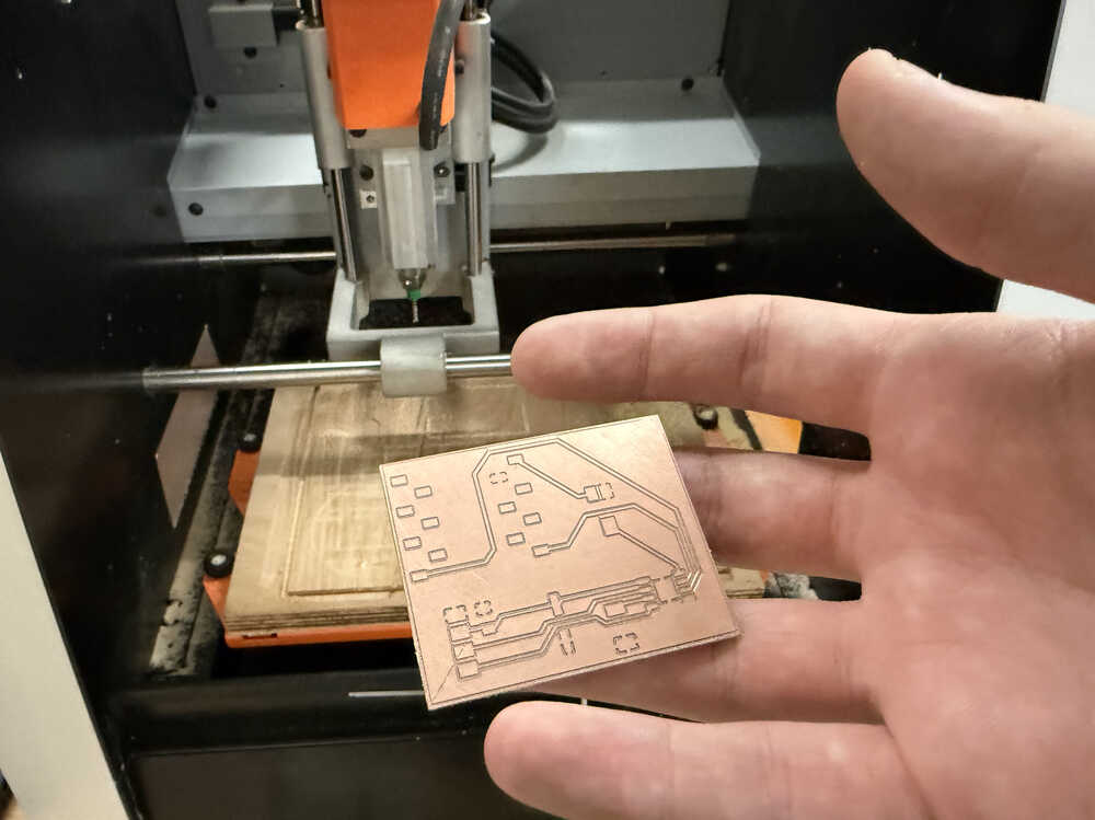
I put the other bit on and started the machine.
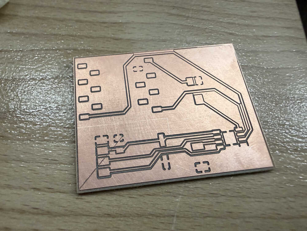
It's out! This is how it looks after washing it with some water.
Soldering
Final Version
Process
Here are the equipment that I'll use.
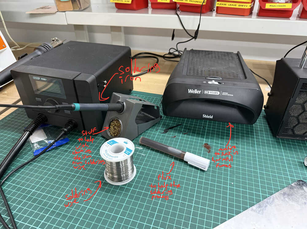
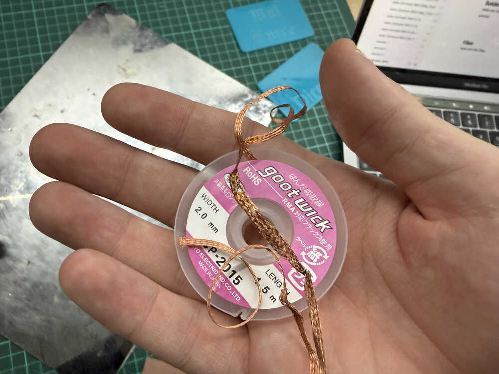
This is some copper to help with cleaning solder from unwanted places.
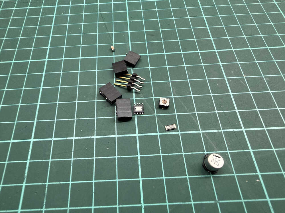
These are the parts that I'll solder onto the board.
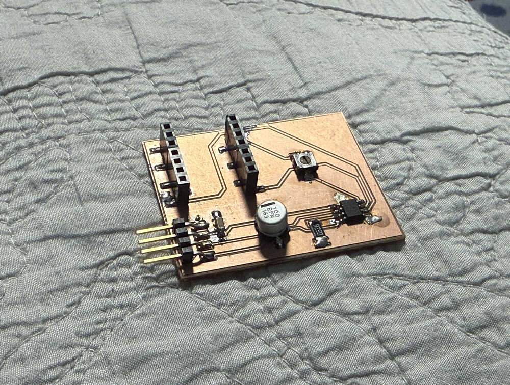
I finished soldering.
My first problem was that, while soldering the XIAO ESP32C3 part, I accidentally broke off two of the pads, so I had to solder those pads back into place. The broken pads are circled below.
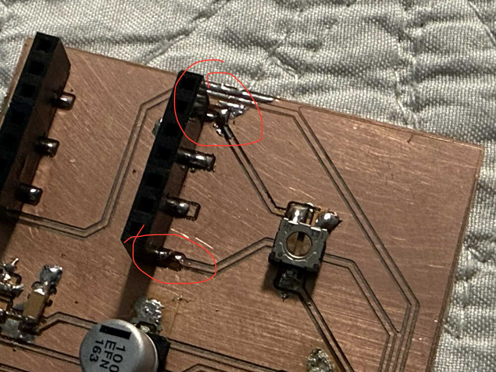
I checked them with my multimeter and, currently, they work correctly.
My second problem was that I didn't have any flux after some point. You see, I had to continue soldering from home, and I didn't have any solder wick or flux with me. That's why I had to put resin on the parts I wanted the solder to be stuck at. Also, I couldn't desolder some parts because, which caused the board to look a bit ugly:
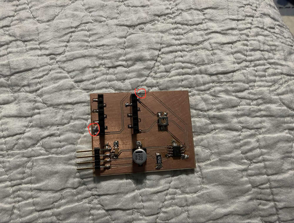
Although, currently, it works correctly. I tested it with a multimeter.
Even though I had some problems, my board is finally finished!
Files
Here are the files.