Week 7, Computer-Controlled Machining
Table of Contents
- Overview
- Resources
- Group Assignment
- Design 1
- Design 2
- Files
Overview
This week, I created a stool and a design for a portable-table.
Resources
- I used Fusion 360.
- I used VCarve.
- I used Cuttle.
Group Assignment
This is the group assignment.
Design 1
Idea
I'm planning on creating a stool for my first design. I need a stool in my room. Sometimes I need to get something from the top section of my bookshelf. I don't want to use my normal chair since it has wheels, which means that it's dangerous to stand on it. Also, sometimes, I want something to rest my legs on, which is why I want a stool.
Final Version

Design Process
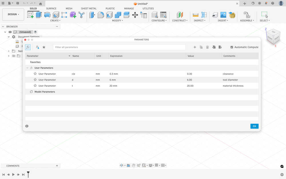
First, I created some parameters.
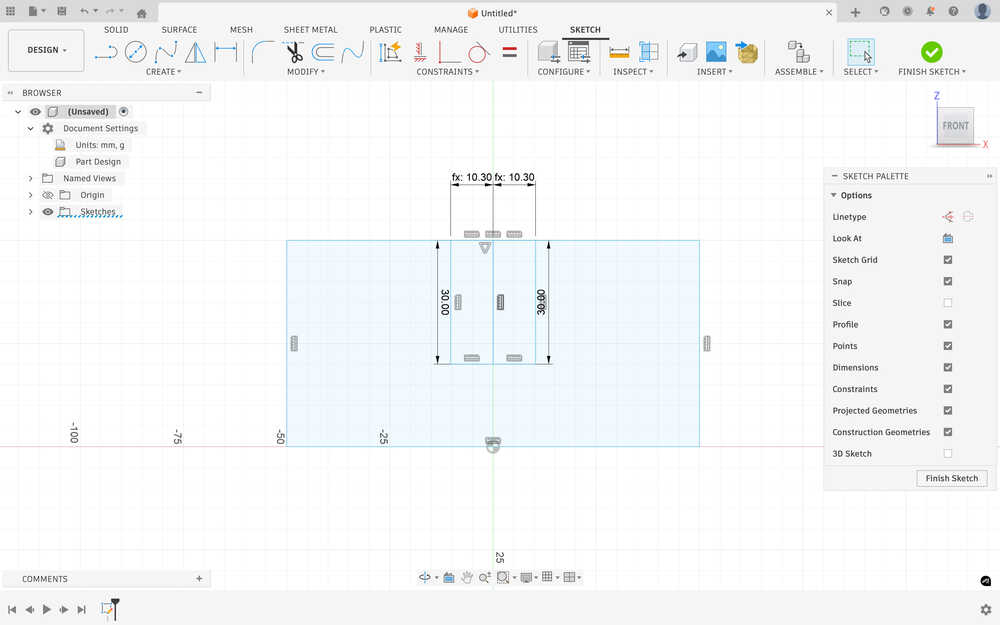
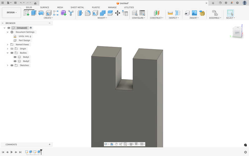
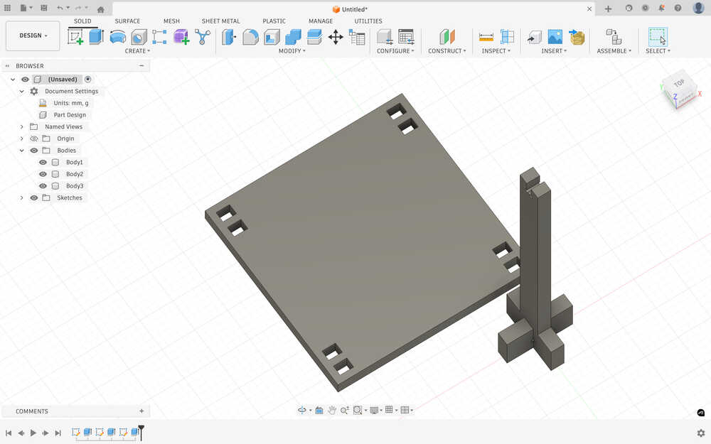
I sketched the first part of a leg. I want the stool to have plus shaped leg base. The middle has the equation material thickness / 2 + 2 * clearance.
I extruded it according to the material thickness.
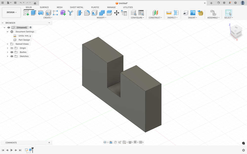
I created another one that'll fit that piece.
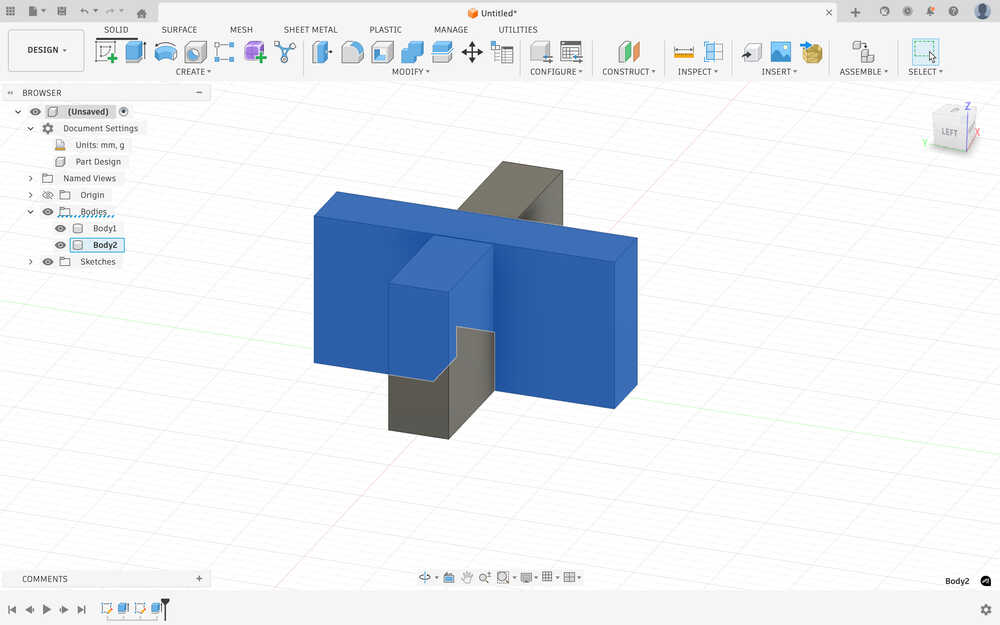
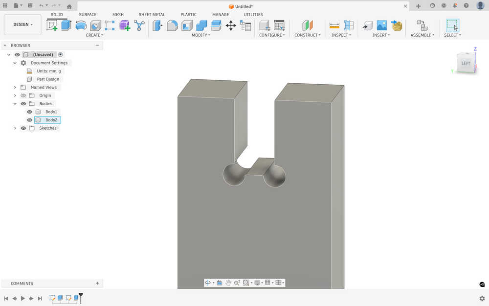
I added don bone fillets with the tool diameter parameter.
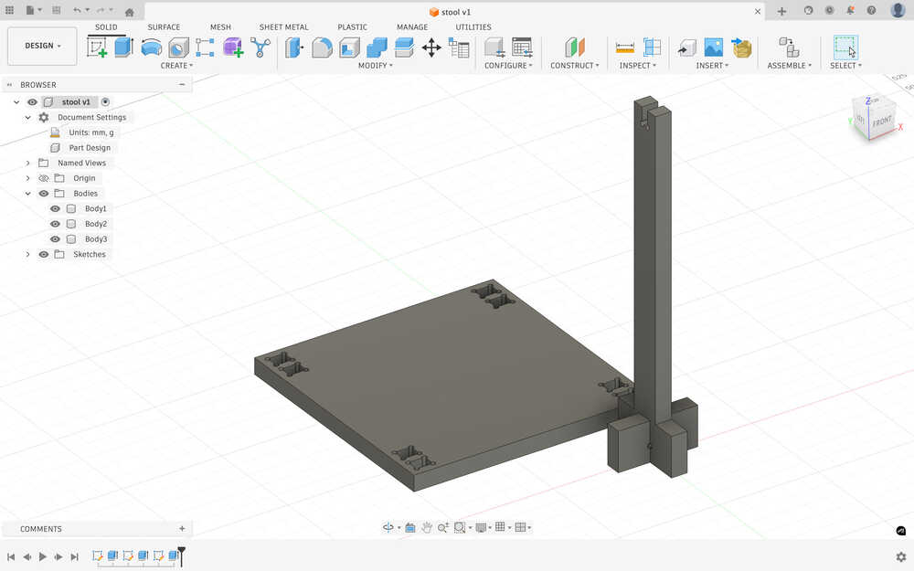
I went back to the design of the second body and added a 350mm by 40 mm rectangle to increase the height of the stool.
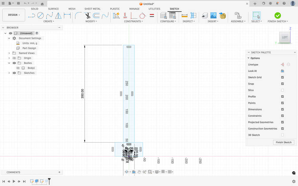
I added another part to connect to the top part of the stool.
I added the dog bone fillet to the new part, too.
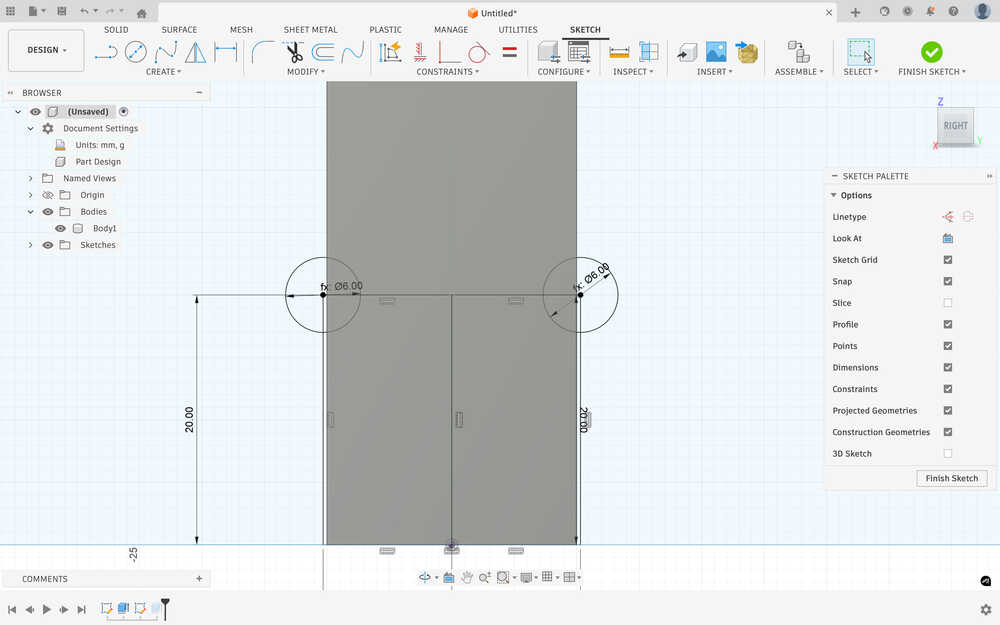
I created the top of the stool with 4 slots to input the legs. I used the three parameters while creating it.
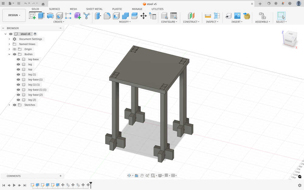
I added dog bone fillets to it.
This is how the stool will look like.
CNC
Put everything horizontally.
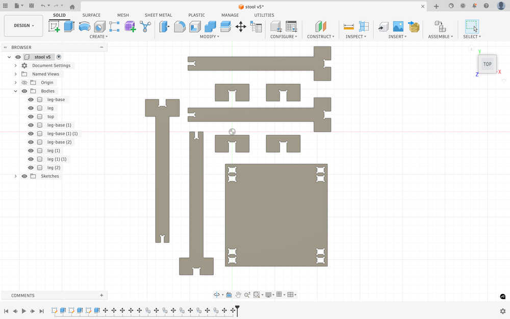
Clicked "Create Sketch" after selecting the face.
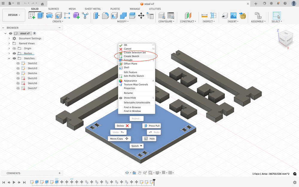
Clicked "Export DXF".
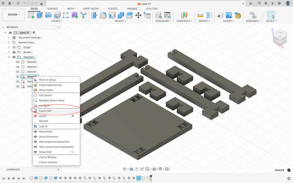
I sent them to the CNC computer through mail.
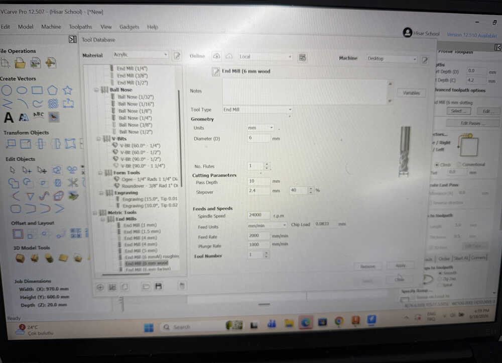
Set the parameters of the 6mm tool tip in VCarve.
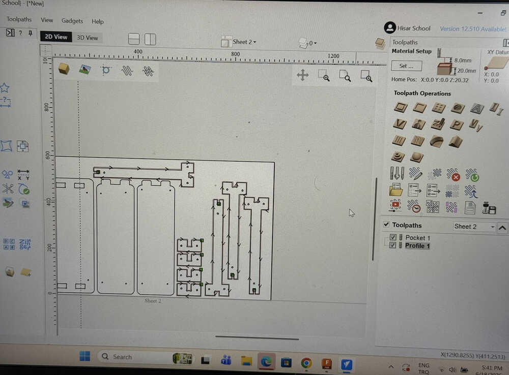
Created the toolpath.
Put the tool tip in.
Placed the 2cm plywood.
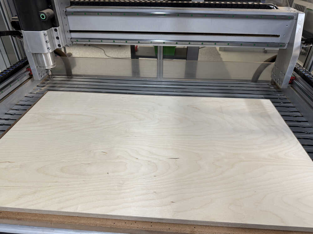
Set the 0 height point.
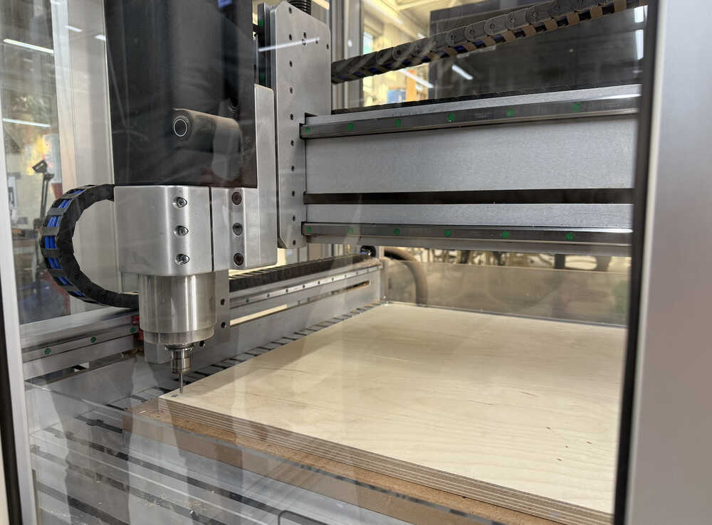
Milling video:
Milling video 2:
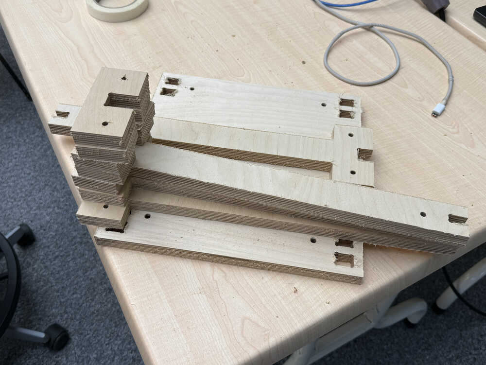
The parts are out.
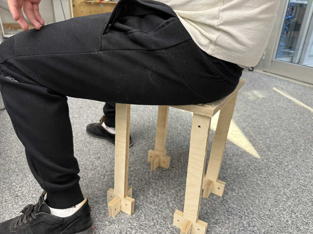
Me sitting on the stool.
Design 2
Idea
I want to design something that can hold my computer, some plates etc. while I'm in bed, on my couch etc. Kind of like a portable table. I'll use Cuttle for this design.
Design Process
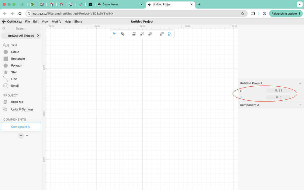
I created two parameters: clearance and tool diameter, which have the values 0.3mm and 6mm, respectively.

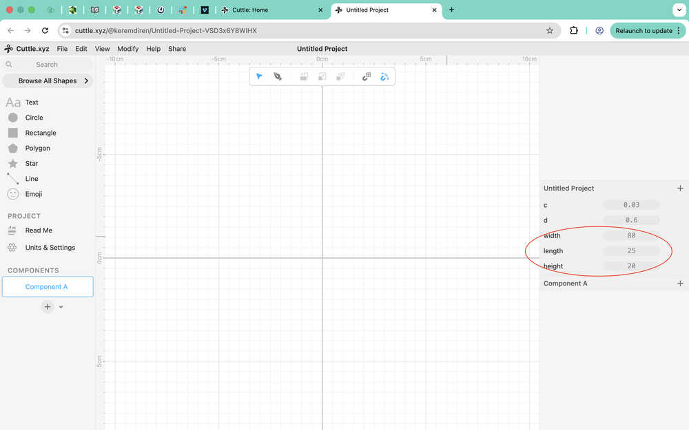
After measuring the width of both my legs together, created a few more parameters.
I later created a material thickness parameter, which has a value of 2cm.
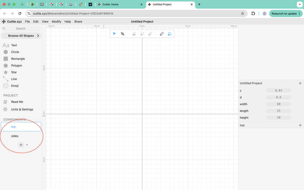
I divided the thing to two components: top and sides.
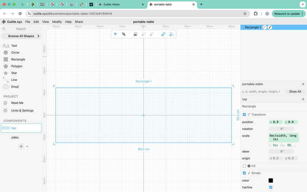
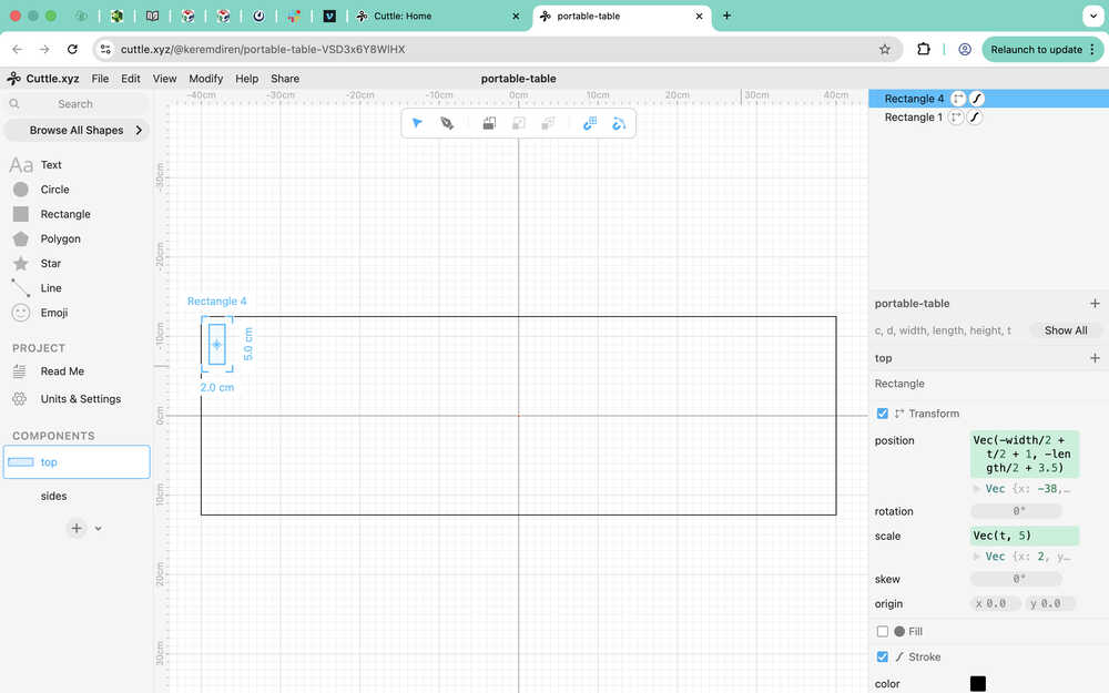
I created a rectangle with width width and length height.
I created a rectangle to use as a connection part to the sides component. You can see the parameters I used at the right part of my screen. I made it so that the hole will always be 1cm away from the left and the top of the big rectangle.
Then, I did this for the other corners, too.
I realized that I forgot to add dog bone fillets and some clearance, so I added those. Here, you can see them scale:
I created two rectangles to use as guides. One with the width width, and the other with the width width/2. The top two rectangles are for the connection to the top component.
I used the pen on the parts.
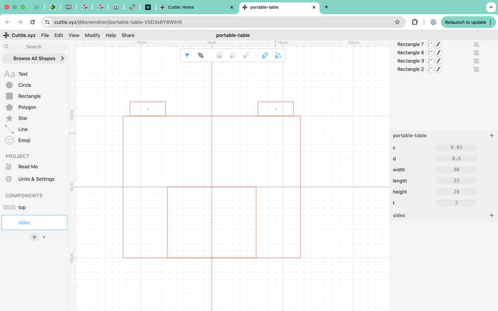
I implemented the parameters. I also added a dog bone fillet to required locations.
Files
Here are the files.