Week 6, Electronics Design
Table of Contents
- Overview
- Resources
- Group Assignment
- Design
- Files
Overview
I created a design for using a DC motor in Kicad.
Resources
I used Kicad and Mr. Krisjanis Rijnieks' Kicad Library.
Group Assignment
This is the group assignment.
Design
Idea
I want to create a PCB that can control a DC motor. I'll probably need an external power supply for this, so I'll add sockets for that.
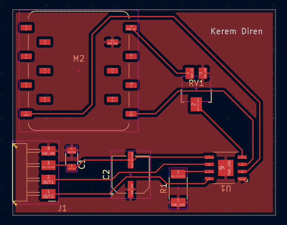
Final Version
Process
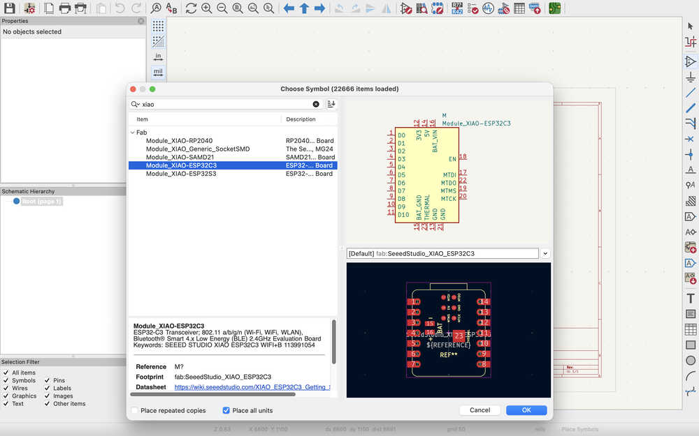
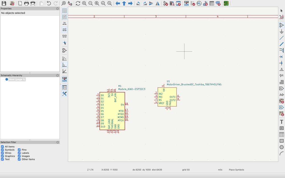
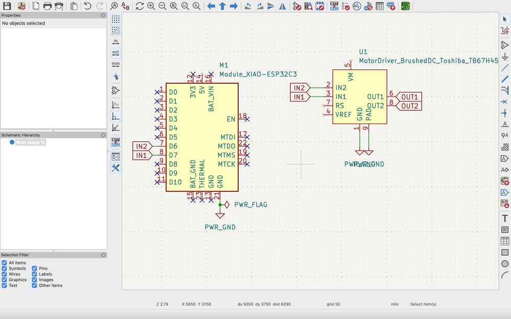
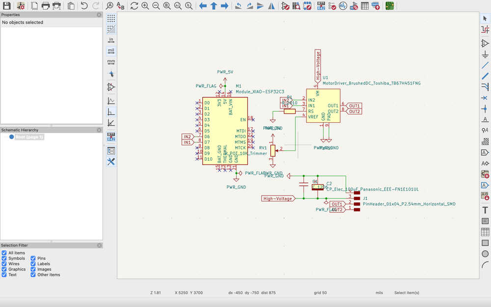
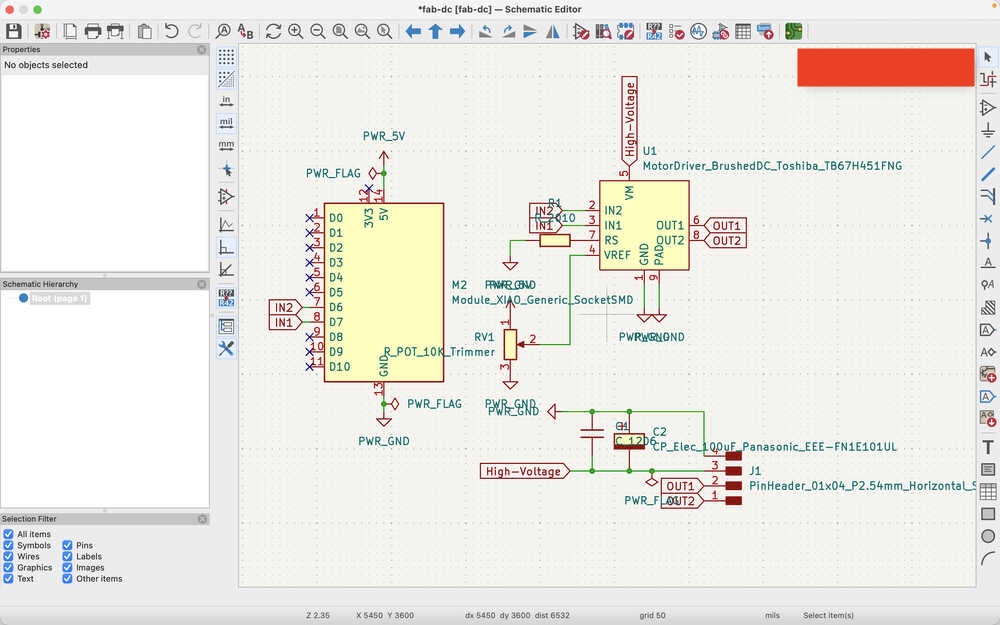
I first clicked the a button to add a XIAO-ESP32C3 to my design.
Then, I added a Toshiba motor driver.
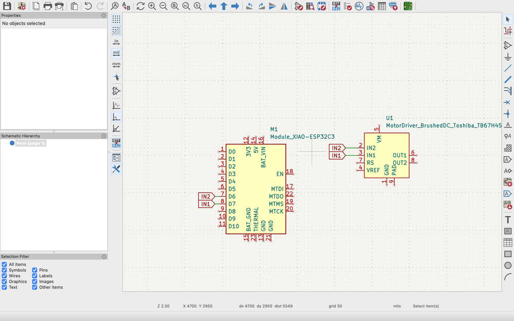
I added IN1 and IN2 labels. This basically connects the two to parts that have these labels to each other.
I placed No Connection flags (which are just an x) to the places I won't be using to show that I'll not be using them.

There's something named ERC (electronic rules checker) that checks whether your circuit design is correct or not. You must place the no connection flags or the check will give you an error.
Using the ground flag, I connected the grounds together. You don't have to use the ground flag to connect grounds, you can just use labels, too, but it's easier to understand this way, I think. Also, when you're creating a power output, you must use the power flag. As it can be seen below, I put a power flag to the ground flag that's connected to the XIAO-ESP32C3. This is because this flag declares the thing its connected to as a power output. For example, putting it there means that the board is supplying the circuit with 0V. If I were to put it to the 5V power output, that would've declared that part such that it's supplying 5V to the circuit. Basically, the parts that has the flag supplies the circuit with the defined voltage, the parts that don't have the power flag uses the voltage.
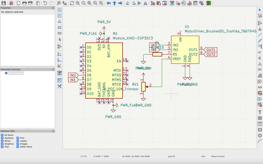
I added a 10k trimmer pot to the VREF port and a resistor to the RS port of the motor driver.
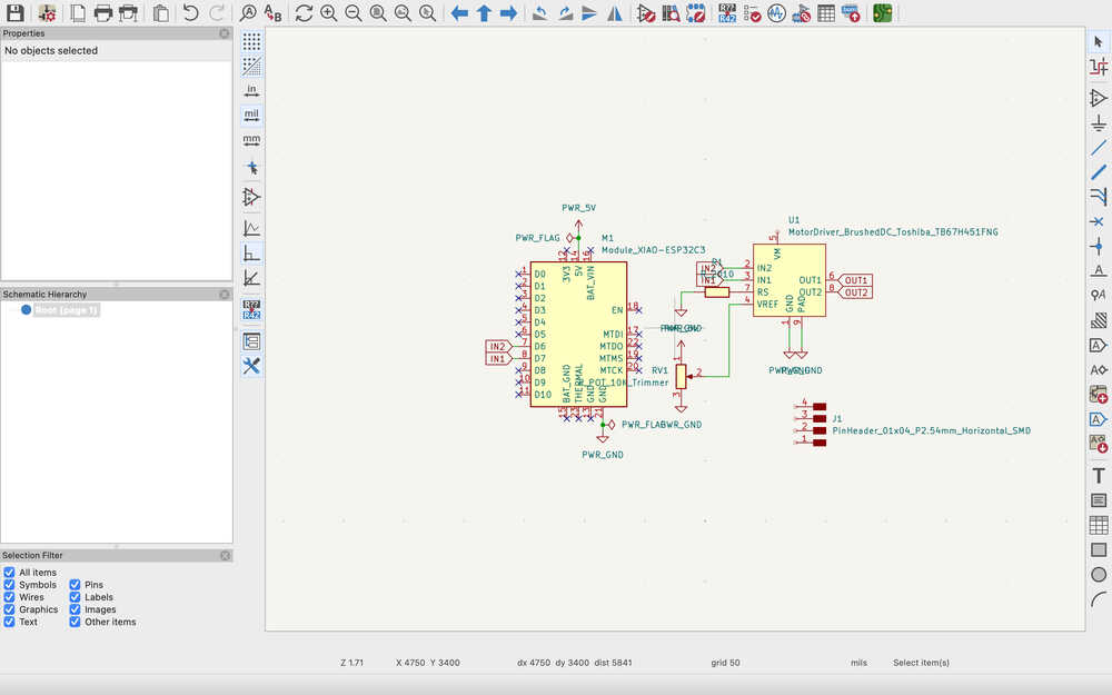
I added a 4 pin headers so that I'll be able to connect the DC motor and the external power.
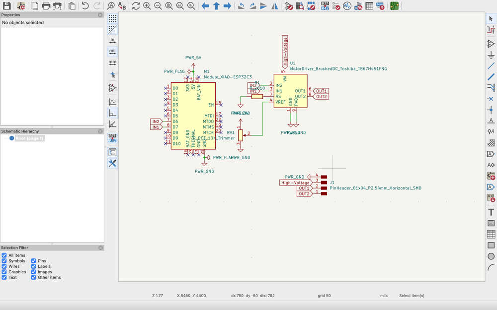
I connected OUT1, OUT2, the socket that'll provide high power, and the ground socket.
Now, I'll be adding a capacitor to prevent voltage fluctuations.
I added a polarized and a neutral capacitor.
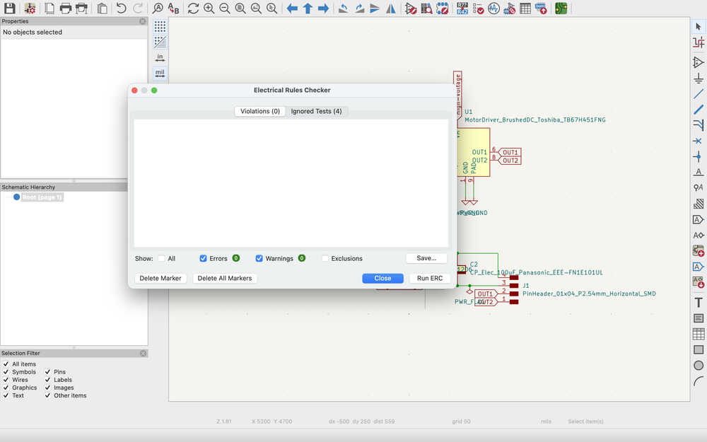
I used the ERC and there were no errors.
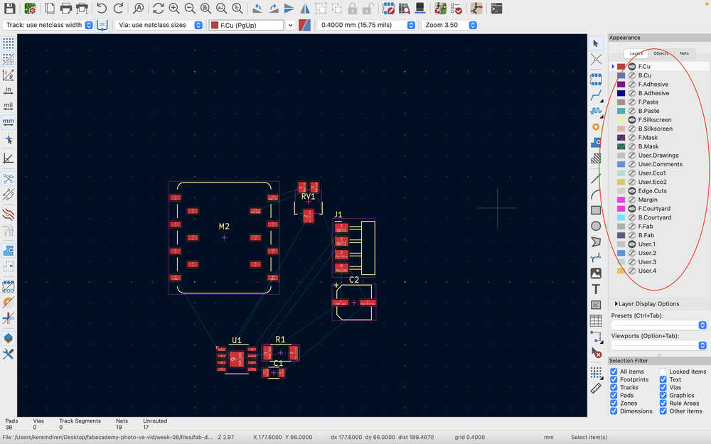
In the board setup part, I clicked the "Update PCB from Schematic" button import the footprints of my design. Thanks to Mr. Kris, the parts I used already had a footprint.
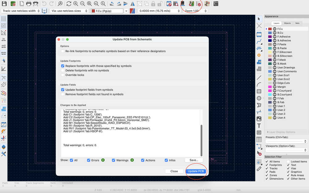
These are the footprints:
I decided to change the XIAO-ESP32C3 to XIAO generic socketSMD since I wasn't sure I would be using XIAO-ESP32C3.
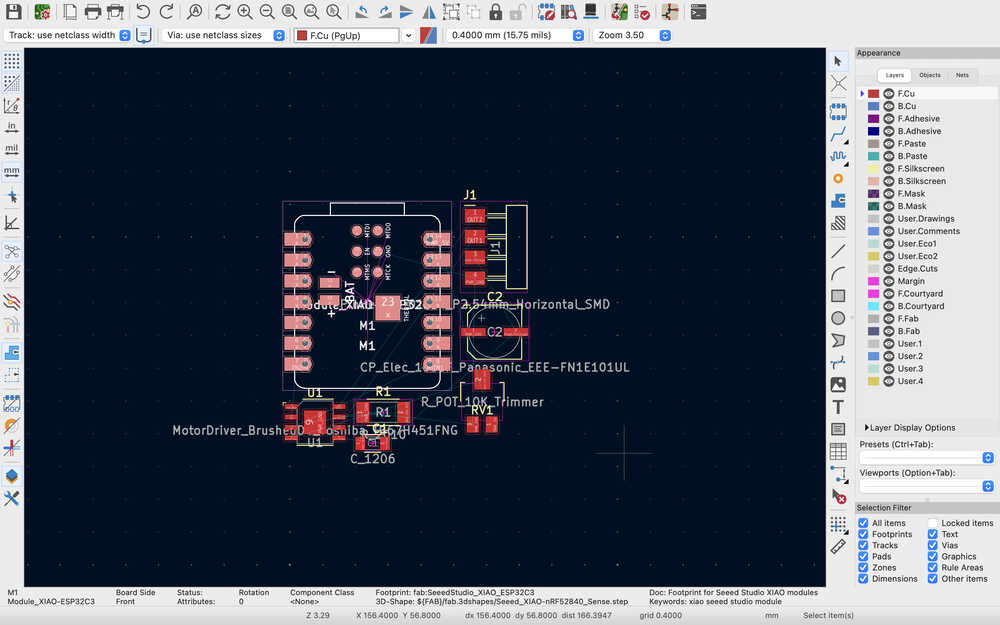
I also clicked update again for the PCB layout.
I hid the things that I wont be using.
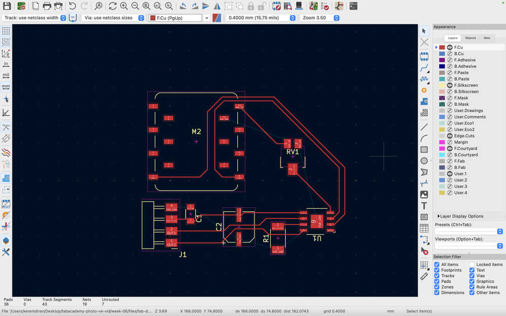
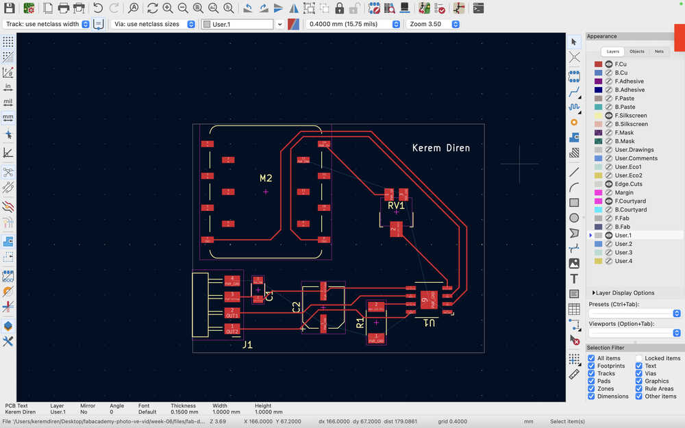
This is how I connected the tracks.
I added a square after selecting Edge.Cuts to set the size of the PCB.
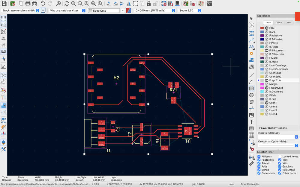
After selecting User.1, I added my name to the PCB.
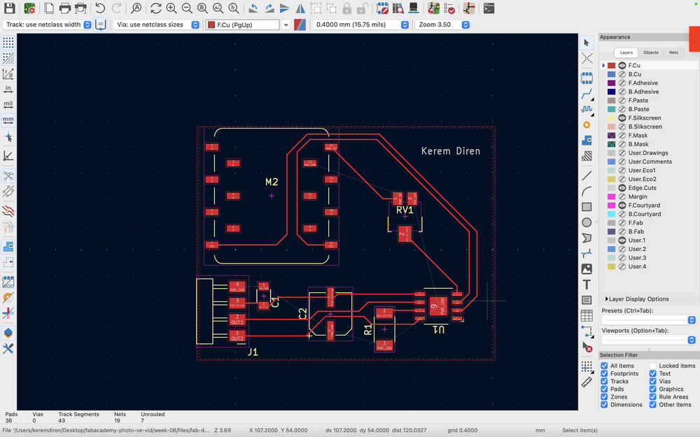
After selecting the F.Cu layer, I clicked the Draw Filled Zones button to add a copper layer to the PCB. Then, I clicked one edge of the PCB, which opened a menu. Then, I selected the ground to connect every ground together.
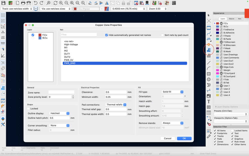
I clicked the other edges of the PCB to define the area.
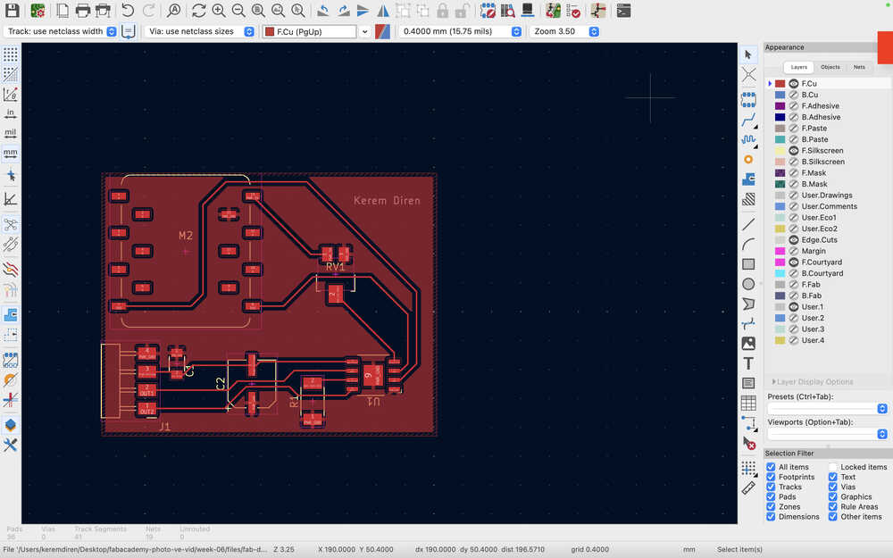
I right clicked the Draw Filled Zones button and clicked Fill All Zones. However, because I wasn't feeling okay with the placement of one of the tracks, I unfilled the zones, changed that track, and filled the zones again. As you can see, every ground is connected.
I ran a DRC (design rules checker).
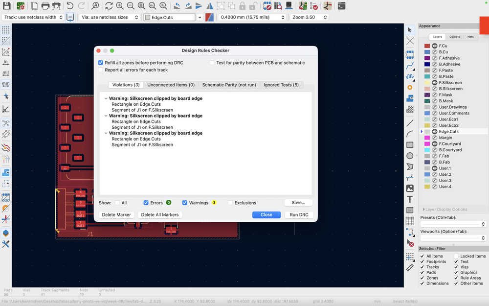
fine since pin sockets need to be there to be easier to connect.
Files
Here are the files.