Week 5, 3D Scanning and Printing
Table of Contents
- Overview
- Resources
- Group Assignment
- Fab Lock
- Prototype
- 3D Scan
- Files
Overview
This week, I created designs in Fusion 360 and printed them using Bambu Lab. I also 3D scanned a friend of mine and printed his 3D model.
Resources
- This is the 3D model of the ultrasonic sensor I'm using.
- This is the 3D model of the servo motor I'm using.
Group Assignment
This is the group assignment.
Fab Lock
Goal of Design
In this design, I want to create a locking mechanism for a door.
Final Version
Design Process
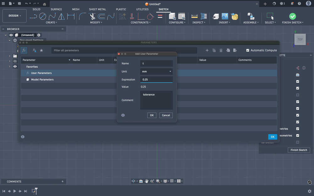
I first started with creating the tolerance parameter, t, with the value 0.25mm.
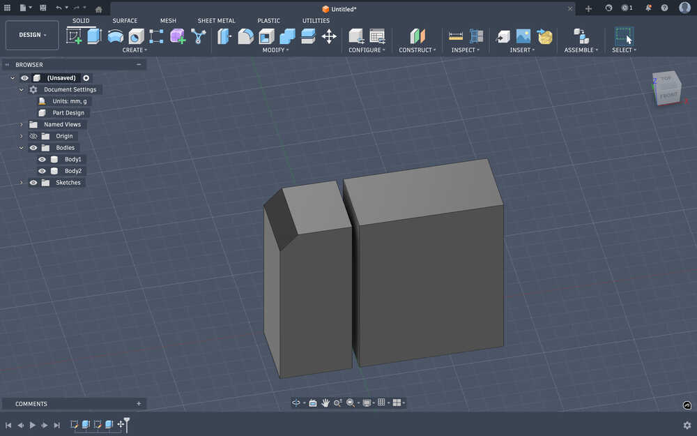
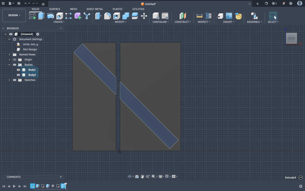
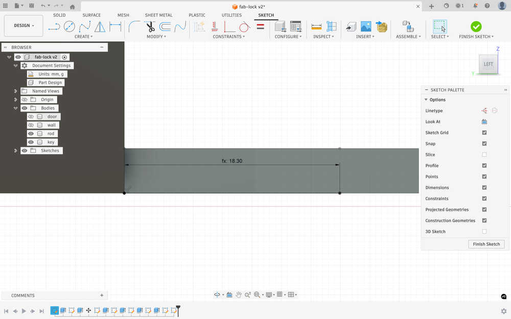
I sketched two rectangles. One is 20mm by 20mm and the other is 20mm by 40mm; they represents the wall and the door, respectively.
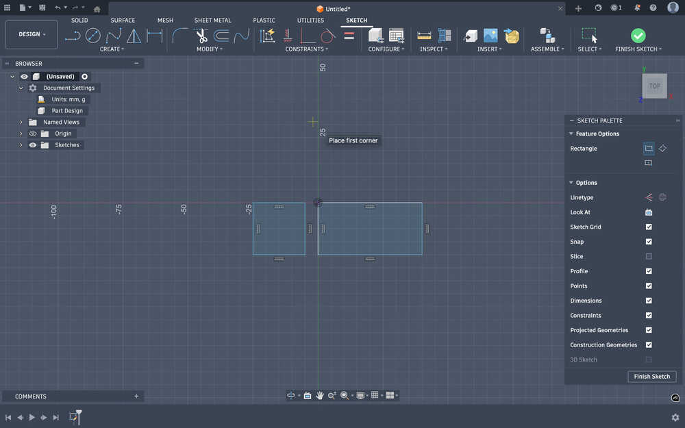
Then, I extruded them to the height 50mm.
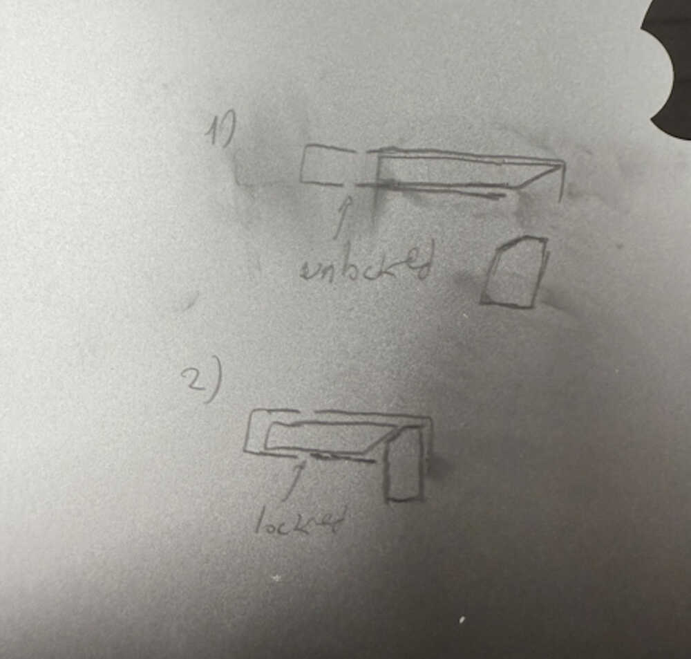
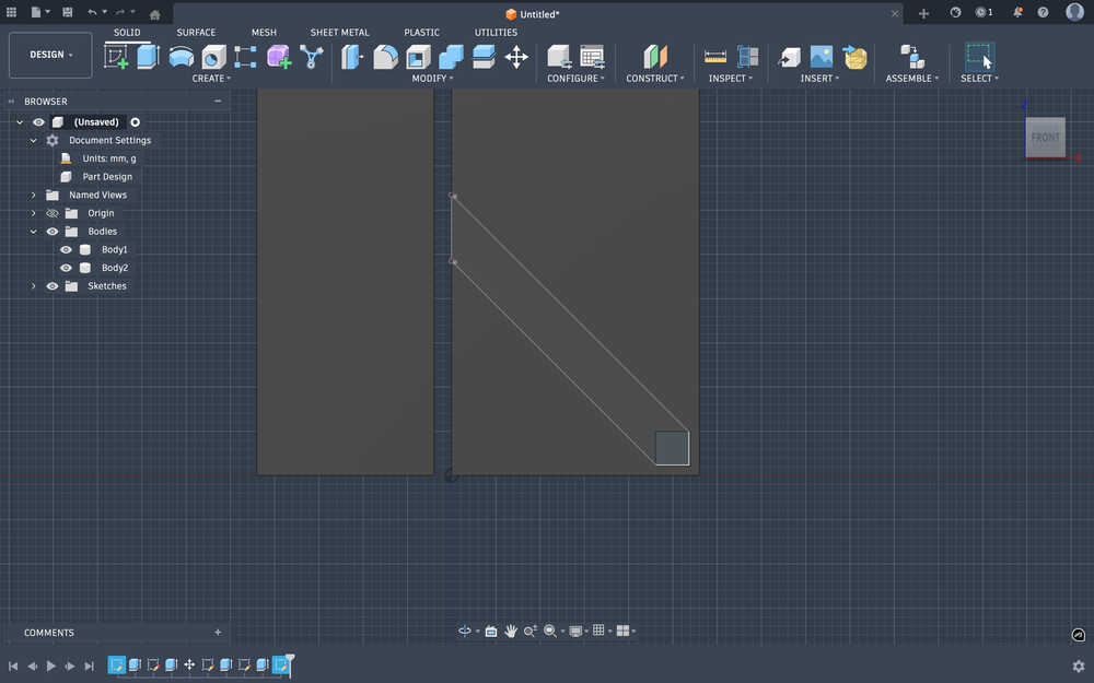
This is a simple sketch of how the lock'll look like:
I created a cut at the wall part. I want the lock part to be insertable from there, too.
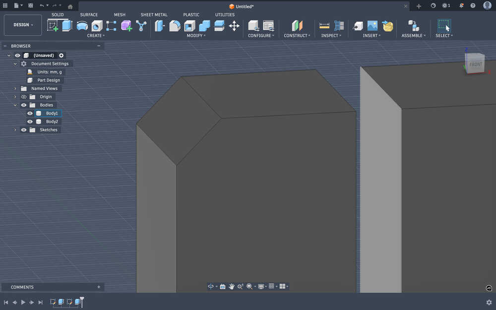
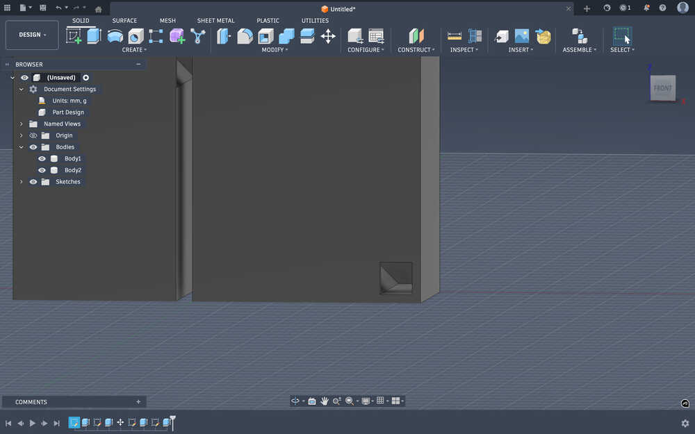
I got the two pieces close to each other.
Now, they're only 2mm apart.
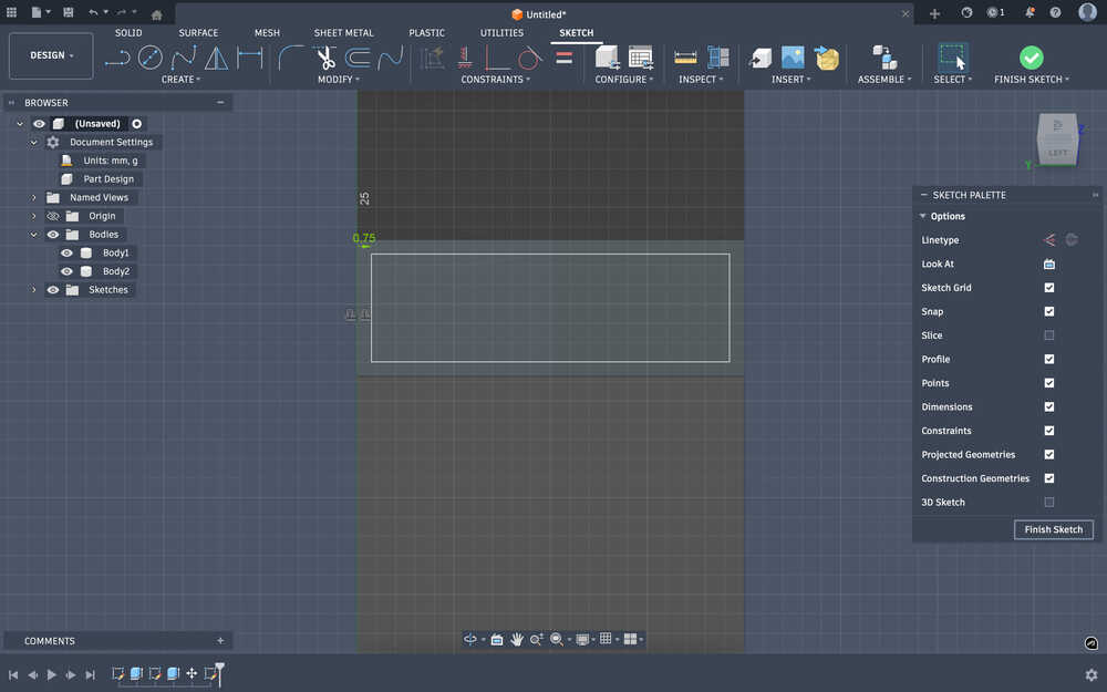
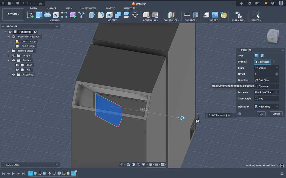
I created an outline of 0.75mm to help with making the hole.
50 - 4.25 * sin(45°) - 2.5 = 44.49479618mm is the height of the hole I'll be creating. Since the hole is 45°, by doing √(2 * 44.49479618^2), I found the depth of the hole to be 62.9251442128. This hole will leave an extra thickness of mm below the lock.
After the cut:
I decided to decrease some of the extra size that the door has. After calculating how much I have to (62 - (44.49479618 + 4.25 * sin(45°) + 2.5) = 12mm), I decreased the size by editing the first sketch I created.
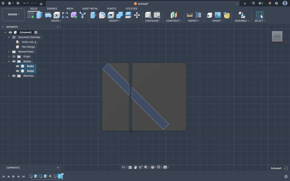
From the two ends of the rectangle hole, I created a hole.
I decreased the t variable to 0.15mm.
I created a sketch for the rod that'll lock the door and the wall.
I extruded it:
Now, I'll create the key that'll be inserted to lock the door. Also, I changed the t variable to the value 0.1mm.
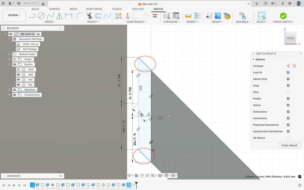
I created a sketch for the key.

I extruded the key. It has a length of 25mm.
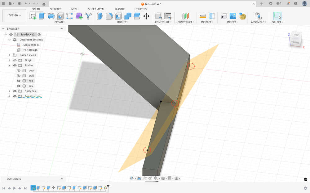
I created 2 lines on the key to use as points for the 3 point plane.
As I was creating the plane, I realized that I did the points wrong, so I deleted the two points, created another point, and created the plane. You can see the points below.
I deleted the parts above the plane for the key and deleted the parts below the plane for the rod.
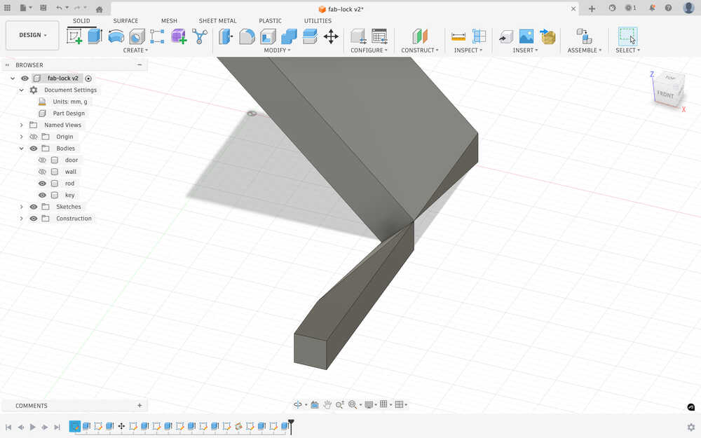
Now, when I insert the key into the slot, the rod will rise and activate the lock.
Because I forgot to measure whether the rise in the rod will be enough for the lock or not, I decided to extend it a little.
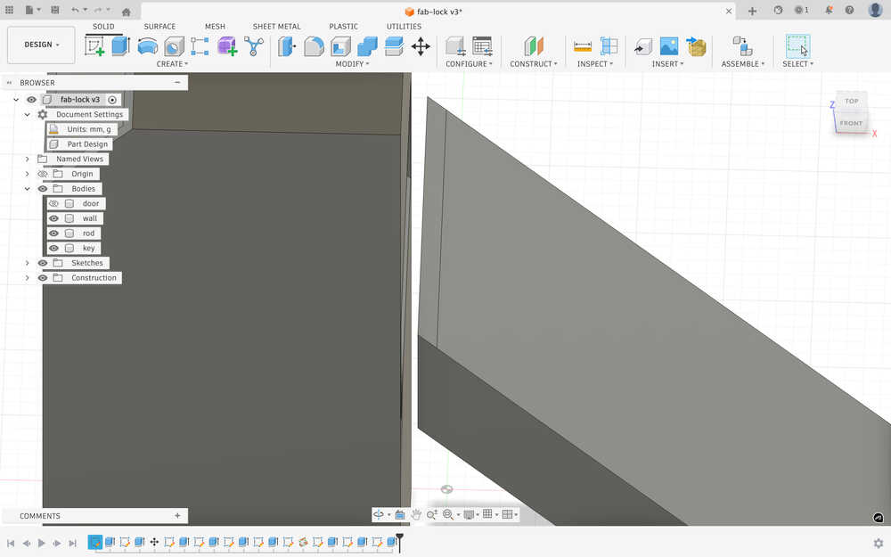
For the extended part, everything except these two lines scales with the t parameter.
Now, when I insert the key, the rod should rise enough so that it activates the lock.
Printing
I sent my file to the printing computer.
Opened my design with Bambu Studio.
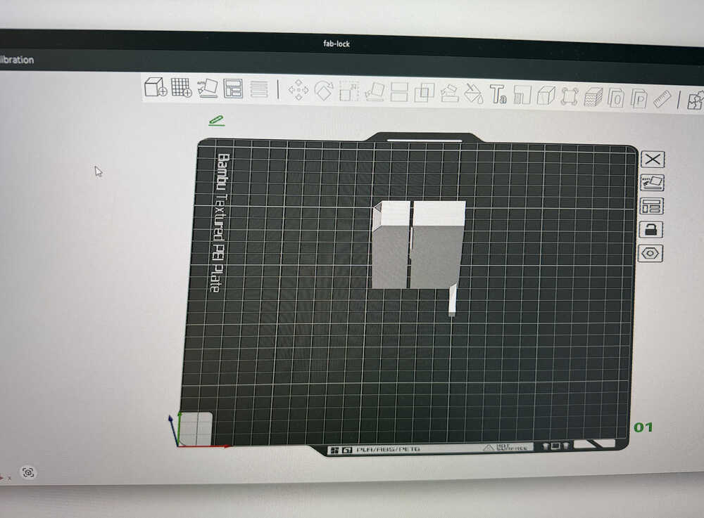
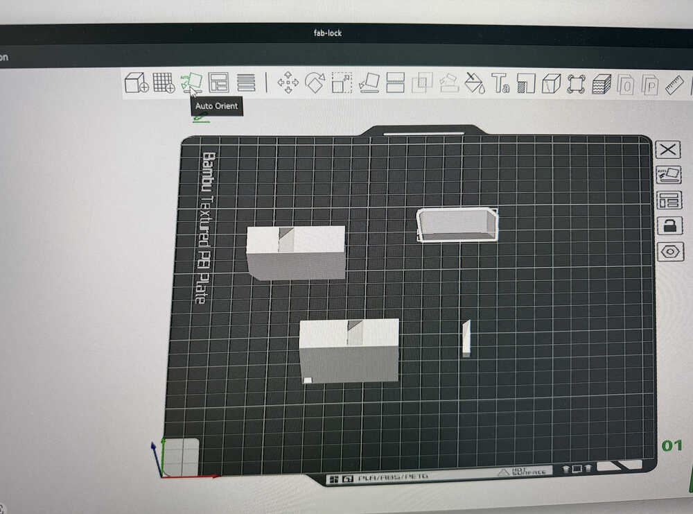
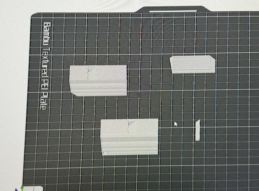
I clicked auto-orient and moved the pieces so that they have some space between them.
I clicked "Enable Support" to help with the printing.
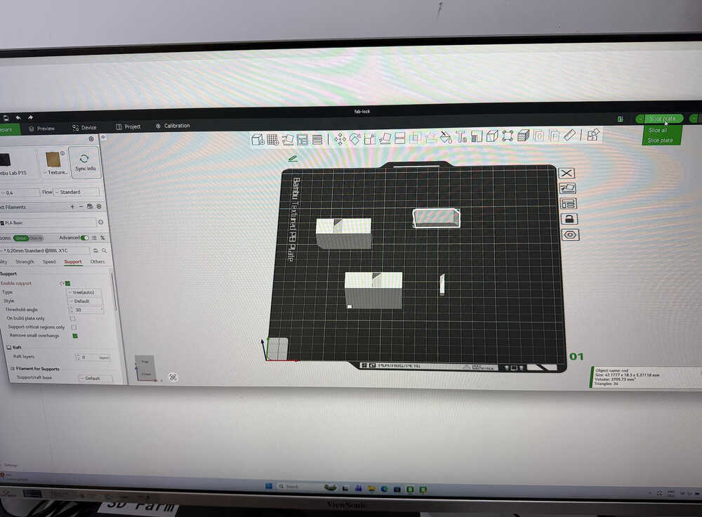
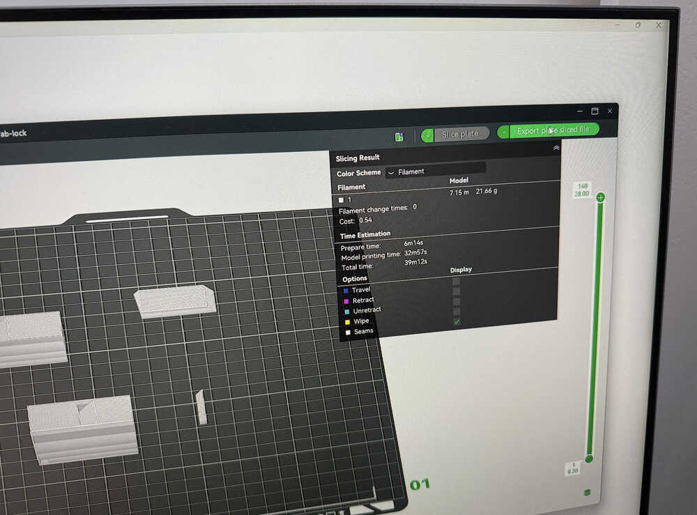
Now, I'll slice the file.
Sliced file:
I clicked "Export plate sliced file".
I opened the Bambu Farm Manager, clicked "Create Task", and imported my sliced file there. Then, I started the printing process.
After I printed it, because the tolerance was too small, the parts didn't fit.
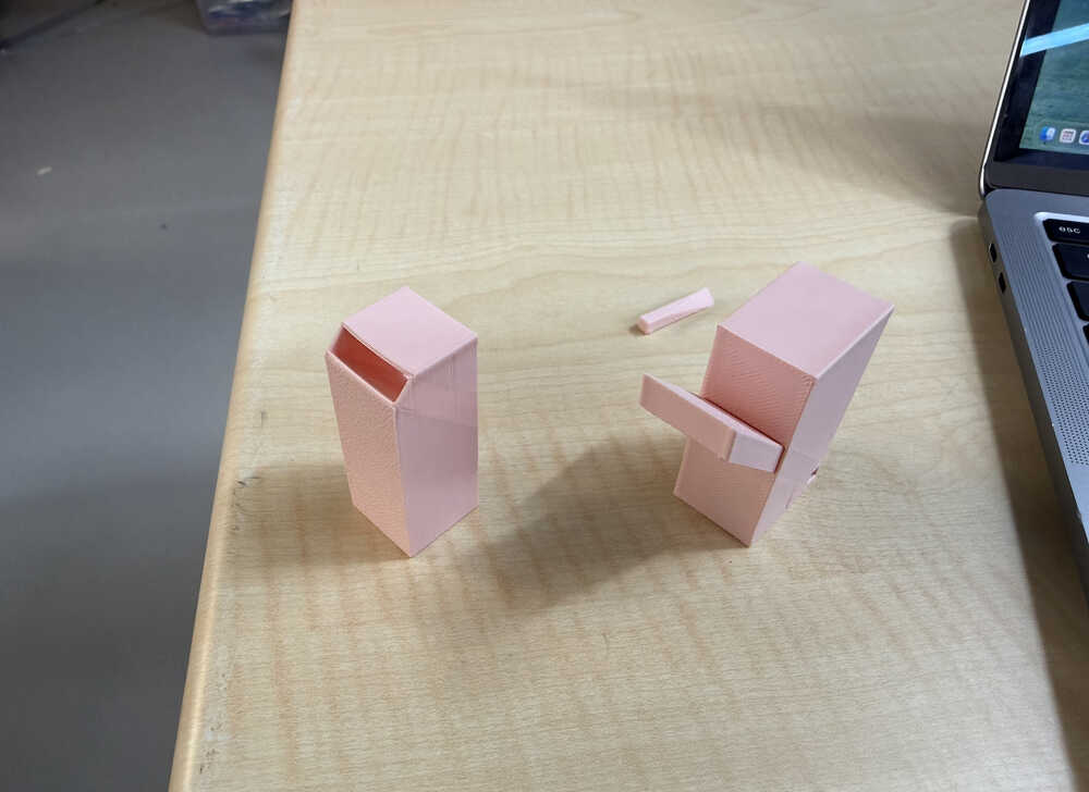
I changed the tolerance to 0.3mm and started the printing process again.
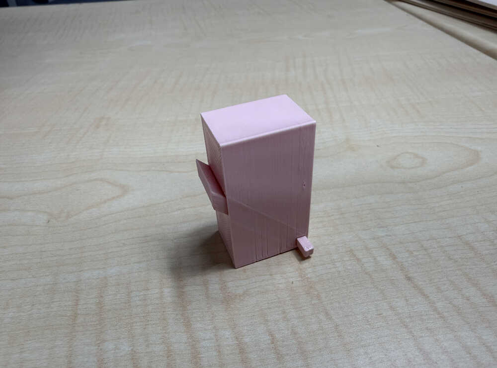
As you can see, the design works. However, because of friction, the mechanism gets stuck sometimes.
Producing this design subtractively is hard because the design has parts that require to be cut at an angle.
Prototype
Goal of Design
I will make a small prototype of my final project in 3D. I will be using servo motors instead of dc/stepper motors because I don't need it to actually move, I just need to see the code work. Also, I decided to use 4 ultrasonic sensors for my final project. Also, I didn't implement the changeable length and sound playing functions in this prototype; although, I might discard the sound playing function idea altogether.
Final Version
Design Process
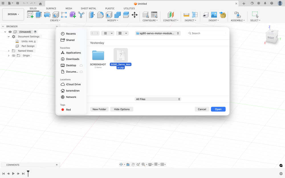
I first started with finding and downloading 3D models for servo motors and ultrasonic sensors. You can find the ones I models downloaded in the resources section.
I opened the files in Fusion 360.
I looked up the dimensions of the two items I'll use.
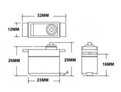
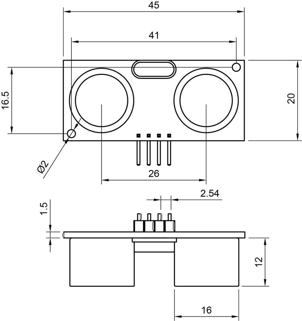
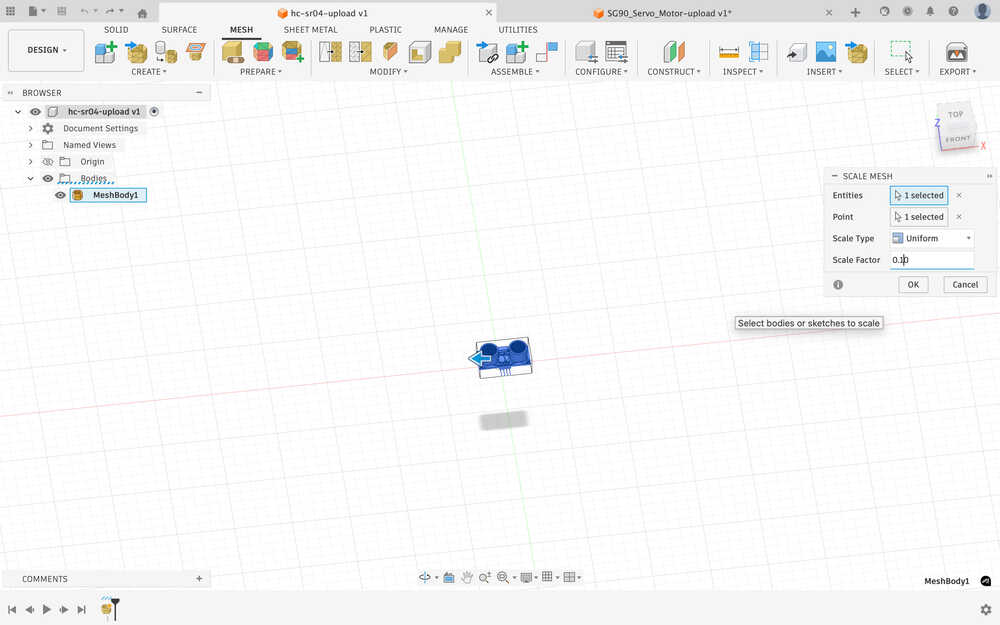
Because the servo motor had the same dimensions, I didn't change its size. However, the ultrasonic sensor was 10x of how big it was supposed to be.
I navigated to the scale option.
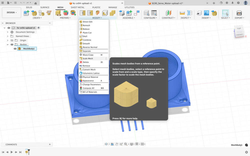
I scaled it to 0.1 times its original size.
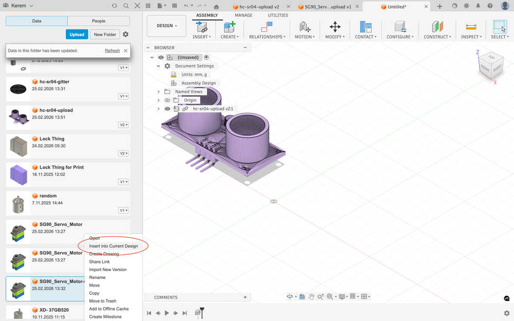
I inserted the two into a new assembly.
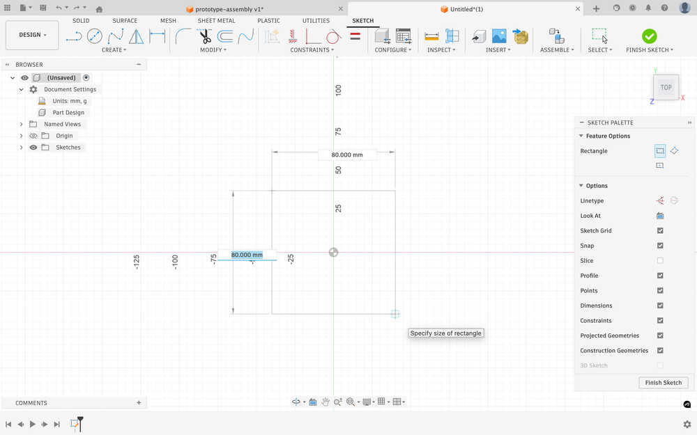
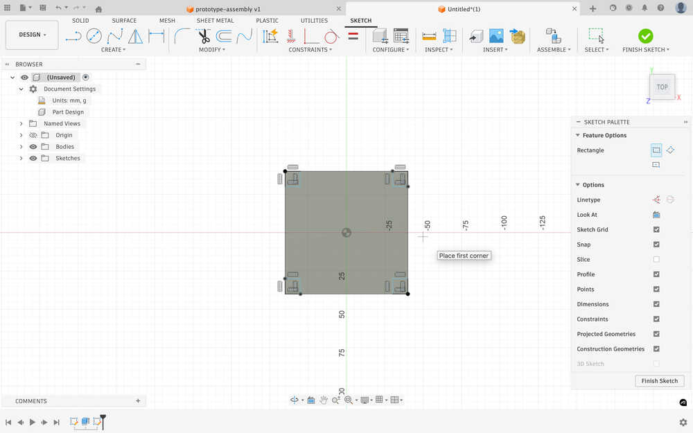
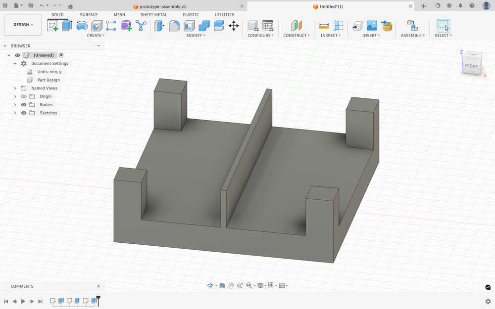
I created a sketch for a platform that'll keep the servos on it.
I extruded it to 10mm.
I sketched 10mm by 10mm squares to connect the platform to the upper body of the bot.
I extruded them to 15mm.
I added a wall to separate the two servo motors I'll use. I might use more motors in the actual design of the bot.
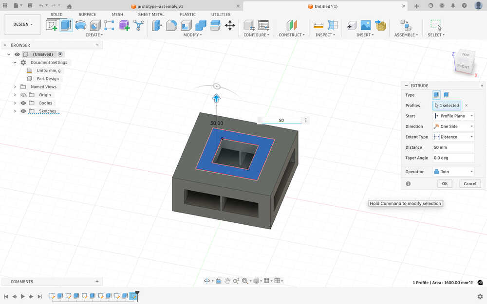
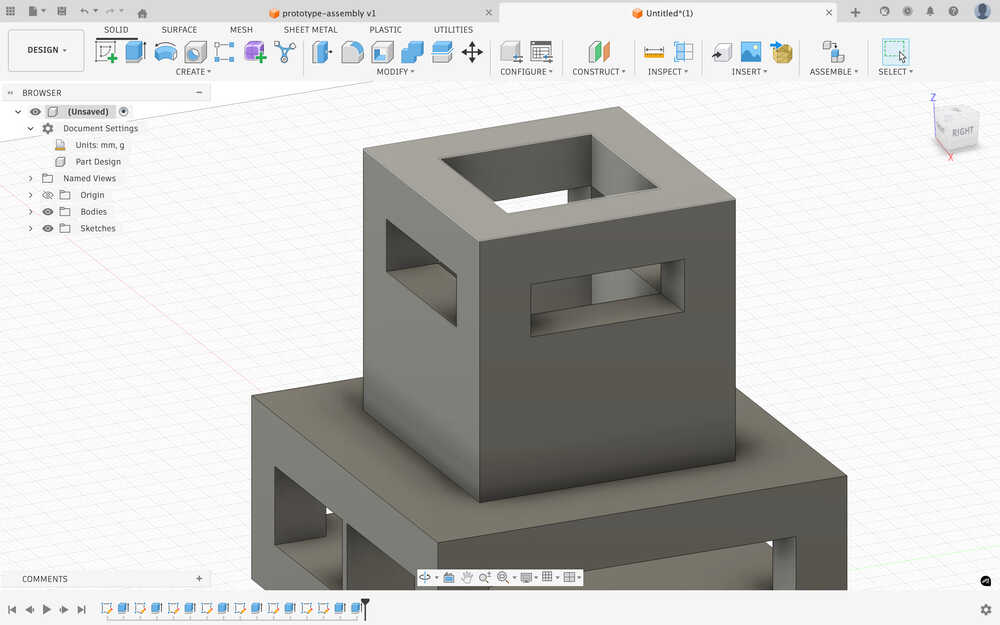
I created another platform above the design and made a hole to give some space to the cables that'll connect to the servo motors.
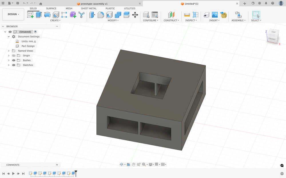
I created a 50mm tunnel to the top.
I sketched a part to get the cables to the ultrasonic sensors.
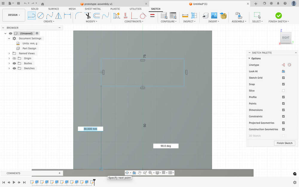
After extruding:
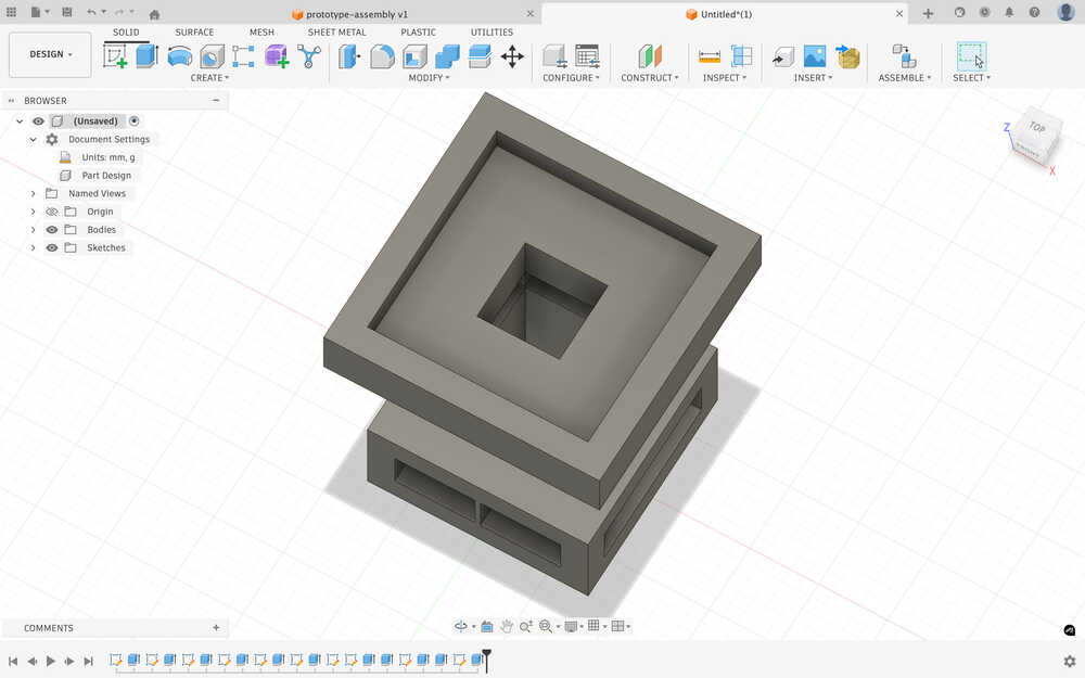
I sketched and extruded a platform.
I created a hole in the middle of the platform.
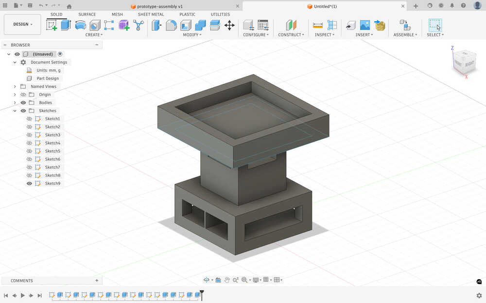
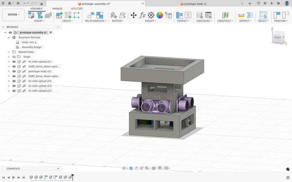
I inserted the body to the assembly.
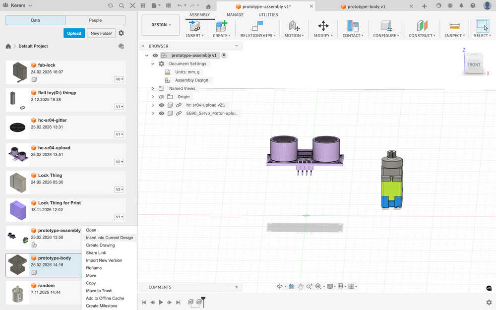
I put everything to their place.
Printing
I exported the design in the .3mf format.
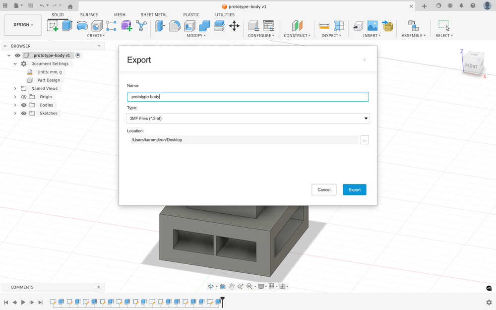
I sent the file to the printing computer.
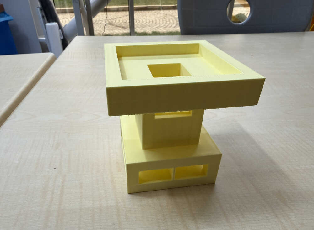
I started the printing process.
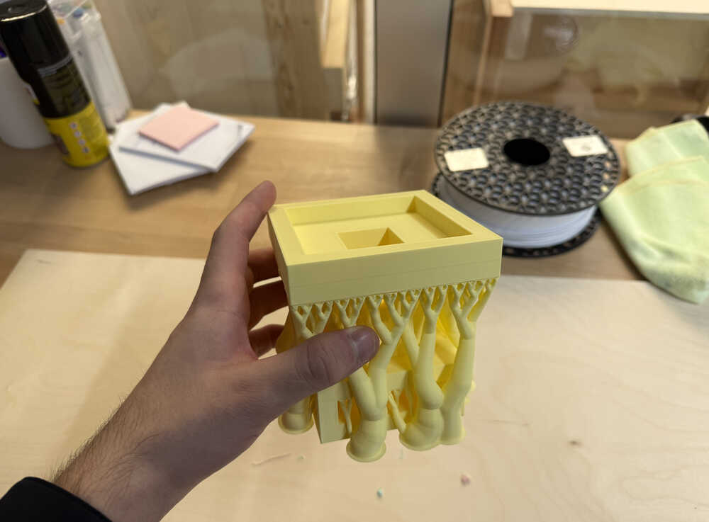
It's out:
3D Scan
Final Version
Scanning
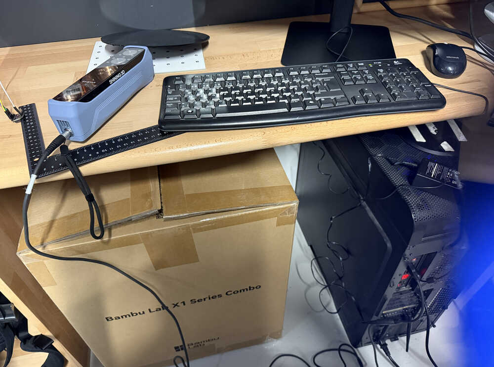
I connected the scanner, cables etc.
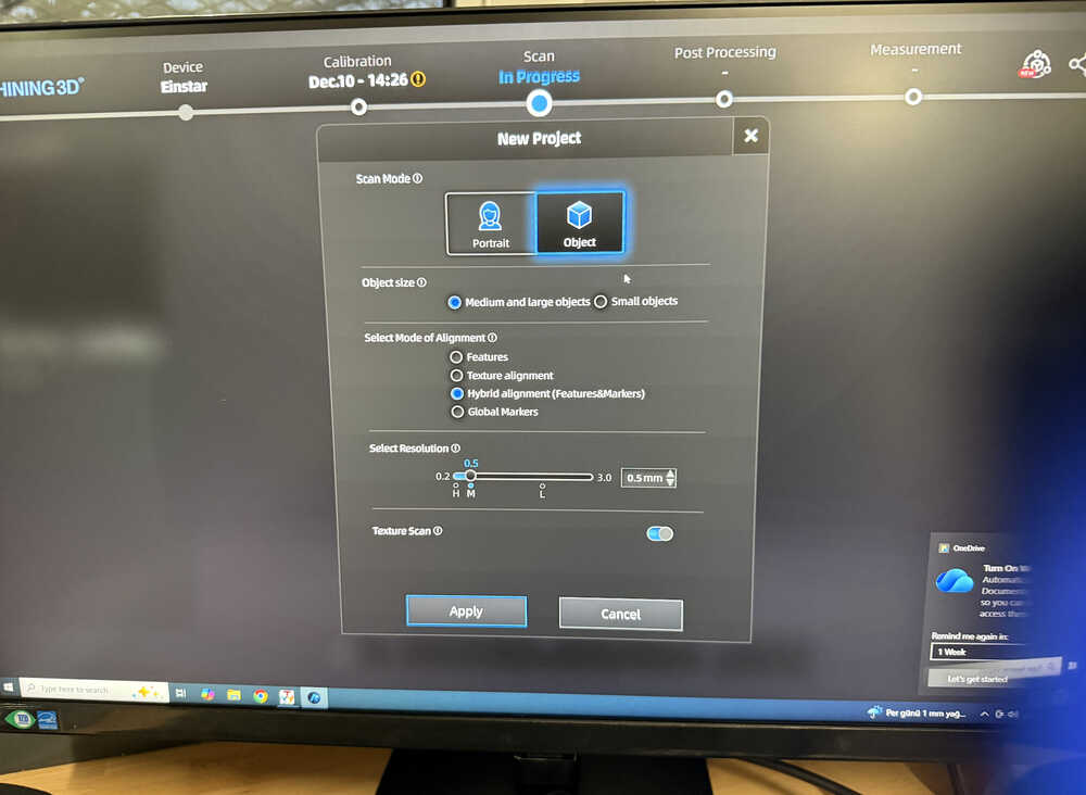
The settings.
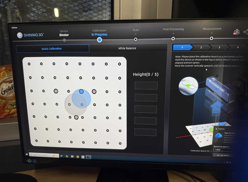
Doing the calibration.
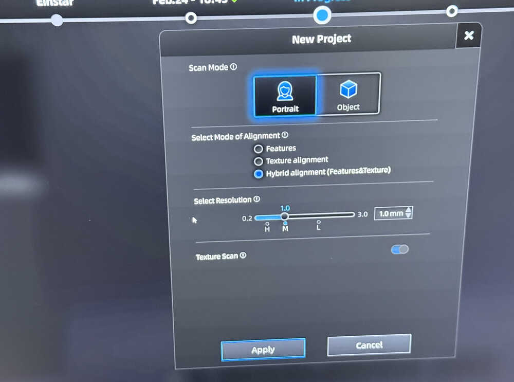
I changed my mind and decided to scan a person.
I scanned him.
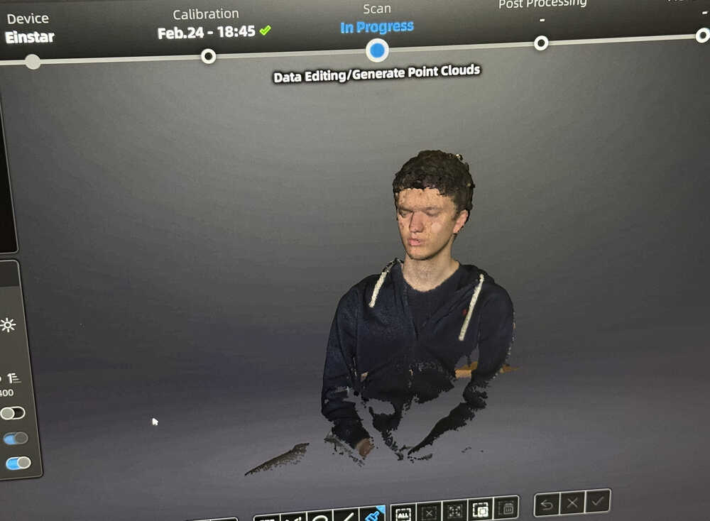
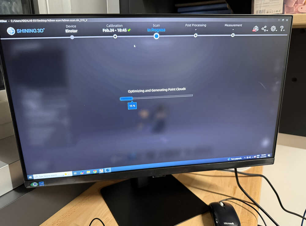
I clicked the "optimize and generate point clouds" button.
I deleted excessive parts.
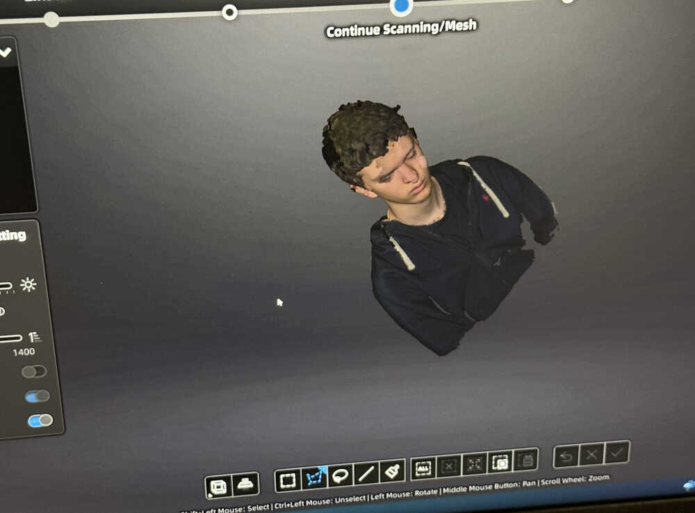
I clicked the button to turn the model into a mesh. Then, I edited some settings and clicked "apply".
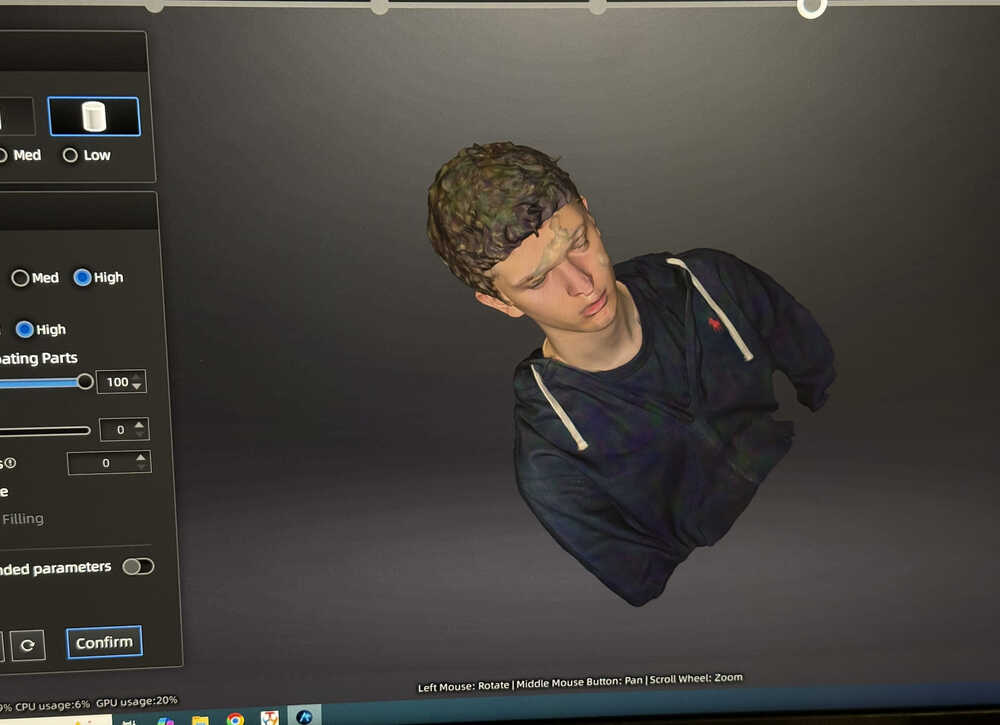
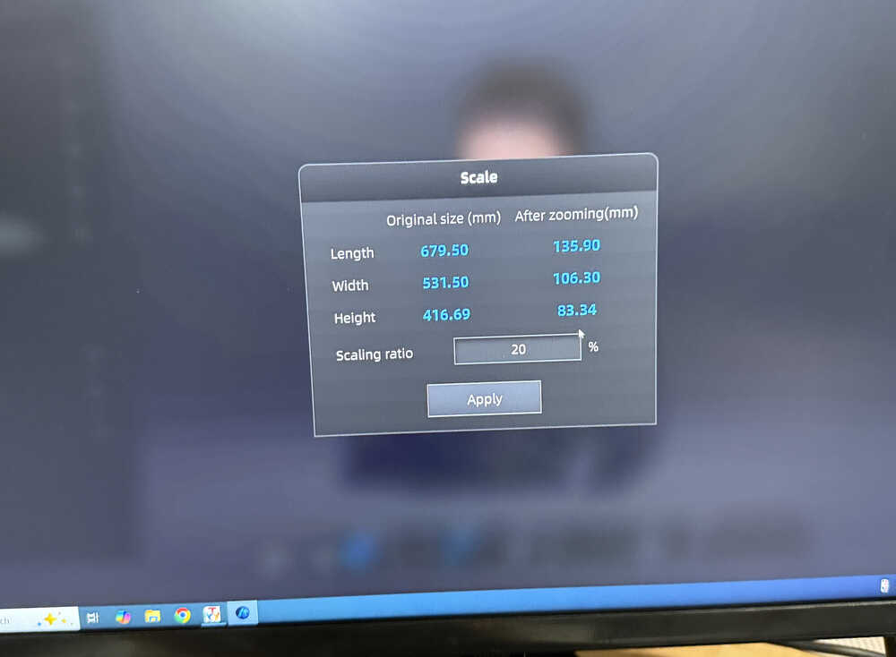
I changed the scale and saved the 3D file.
I'll not put the file into my repo since it's size is really big.
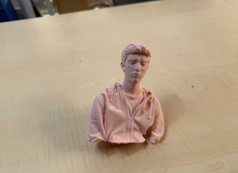
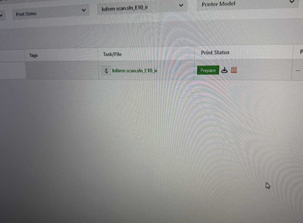
I started the model's printing process.
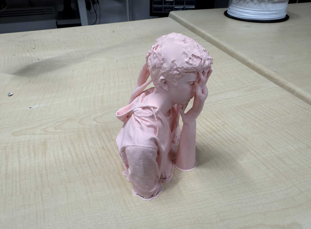
It's out:
Files
You can download the files from here.