Week 3, Computer-Controlled Cutting
Table of Contents
- Overview
- Resources
- Group Assignment
- Cutting Vinyl
- Cuttle
- Lazer Cutting My Designs
- Post-Week
- Files
Overview
I cut vinyl using Cricut to create a sticker of oen of my 2D designs I designed in week 2. I also used Cuttle to design a park made of wood. I used an xTool lazer cutter to cut, score, and engrave the Cuttle design I created this week.
Resources
- I used Cuttle.
- This is where I learned about parameters in Cuttle.
- I used Cricut to cut vinyl.
- I used xTool to lazer cut, engrave, and score some wood.
Group Assignment
Here's the group assignment.
Cutting Vinyl
Final Version
Cutting Process
I first exported one of my designs in .svg format. Then, I sent my design to the computer that I'll use to use Cricut.
I uploaded the file to Cricut.
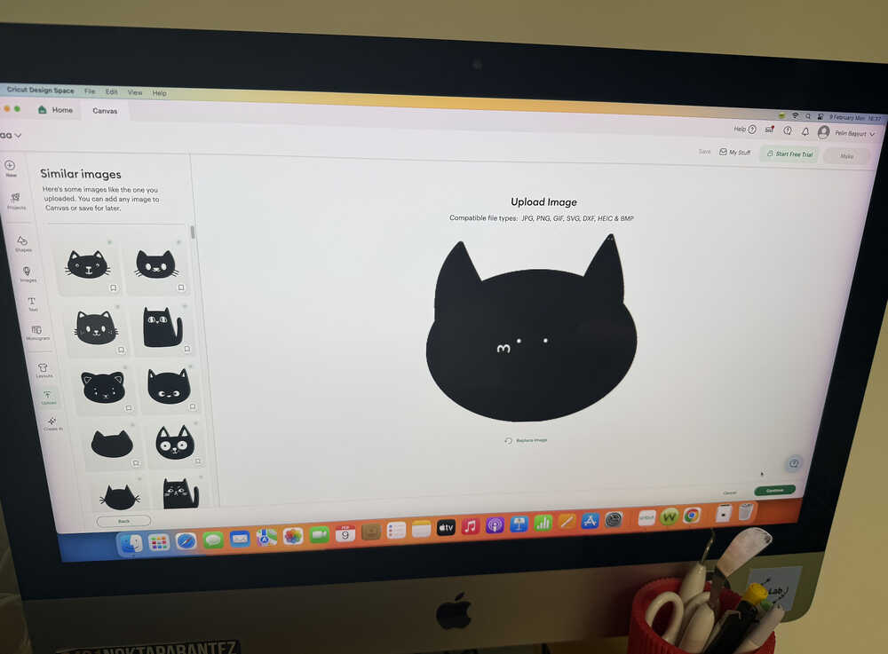
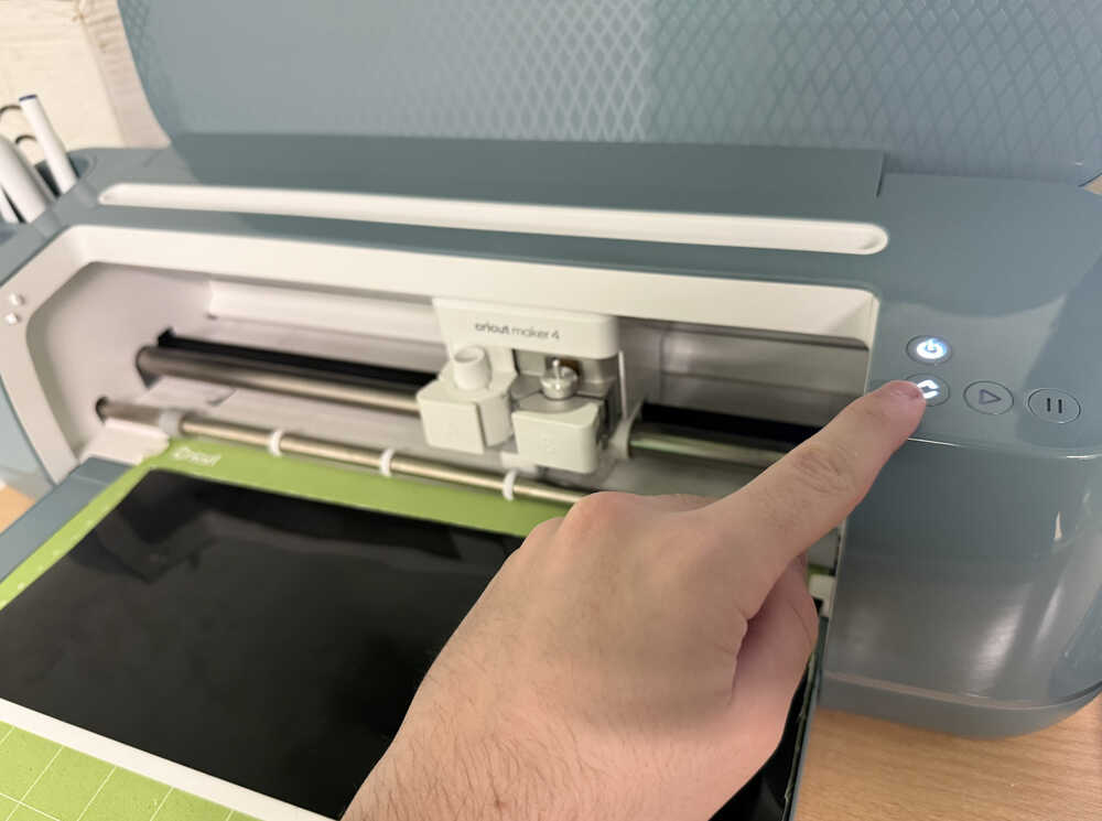
I clicked the "make" button at the top right corner of my screen.
As you can see here, there's just too much ears and heads, so I deleted some.
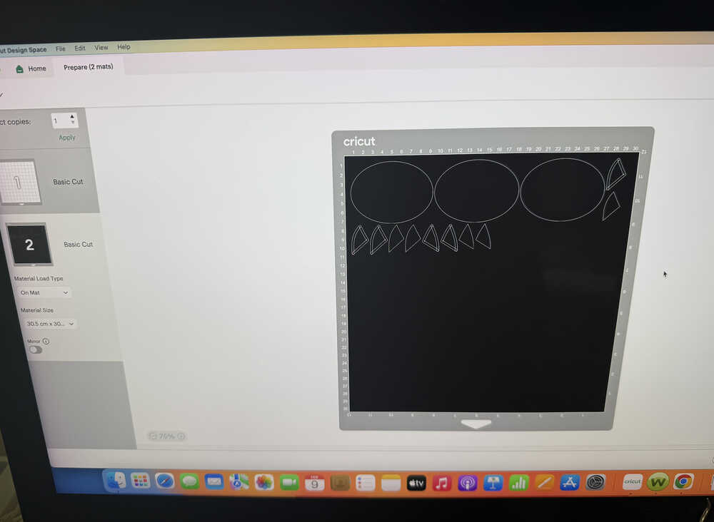
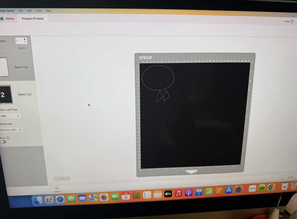
This is how what the black layer currently looks like.
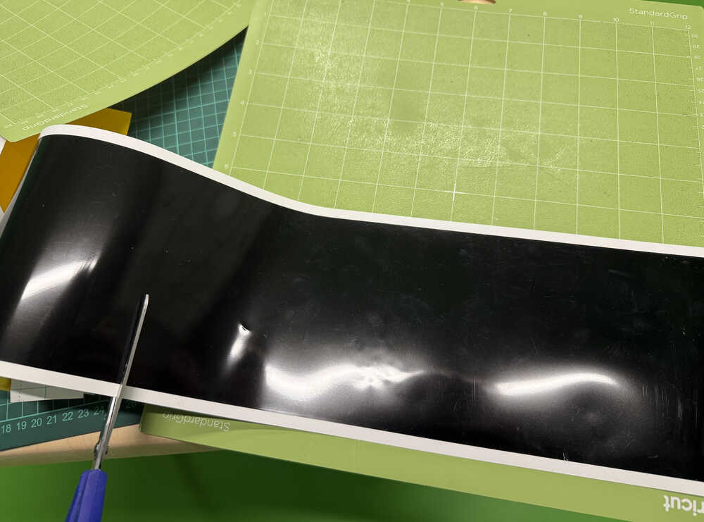
I took some black smart vinyl and cut it.
I clicked "continue" and selected the type of material I'm using.
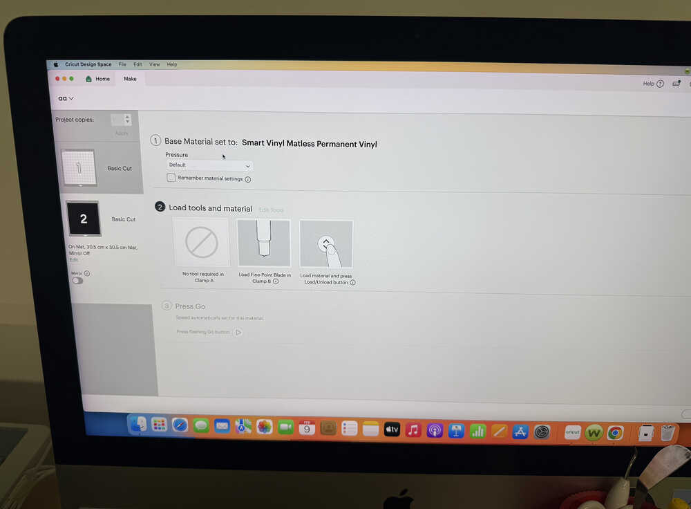
I measured the mat length.
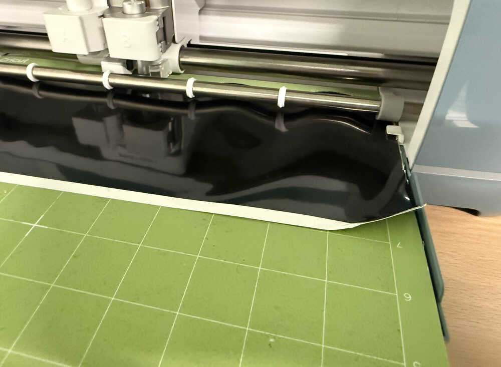
After measuring, because the chunk of vinyl was too big, the material lost its shape.
After cutting the vinyl to a smaller piece, I clicked the measure button again.
Cricut in action:
I repeated the exact same process for the eye and mouth parts. However, I used yellow smart vinyl instead of white because I thought it would look better. Also, I had to do this part one more time since the vinyl wasn't stuck to grip good enough. I used a bigger piece of vinyl the second time I started the cutting process.
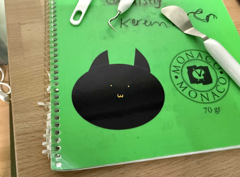
The two pieces are now ready.
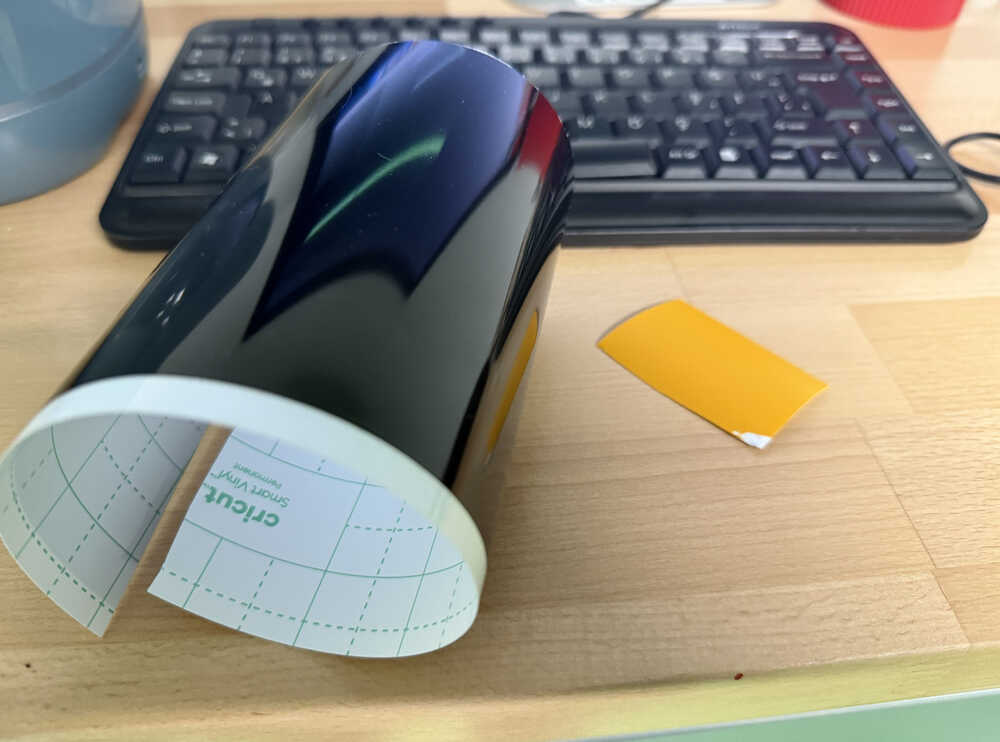
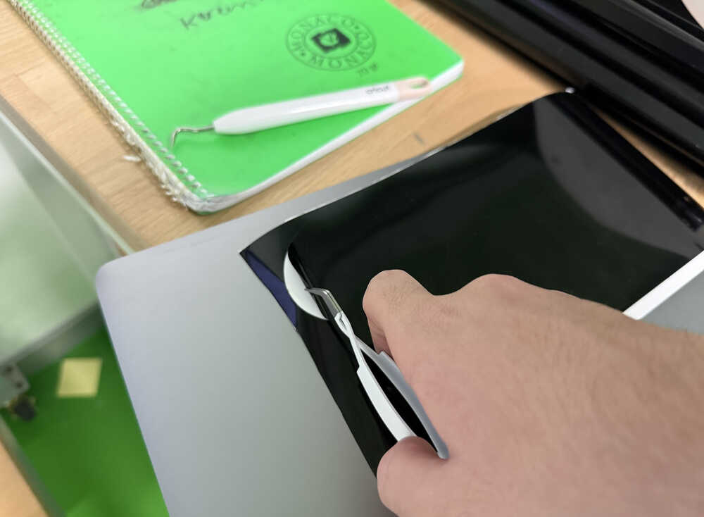
Using tools, I separated the parts and put then on a notebook of mine.
Cuttle
Design Goal
I'm planning on creating a park. The park will have benches, trees, a ground, cottages(made up of a wall and a door), a path(will be created by engraving), people, and some grass. I will also recreate the connection parts I created in week 2. However, among them, I will only use the 90°-connection, 180°-connection, and the 90°-90°-connection.
Final Version
Design Process
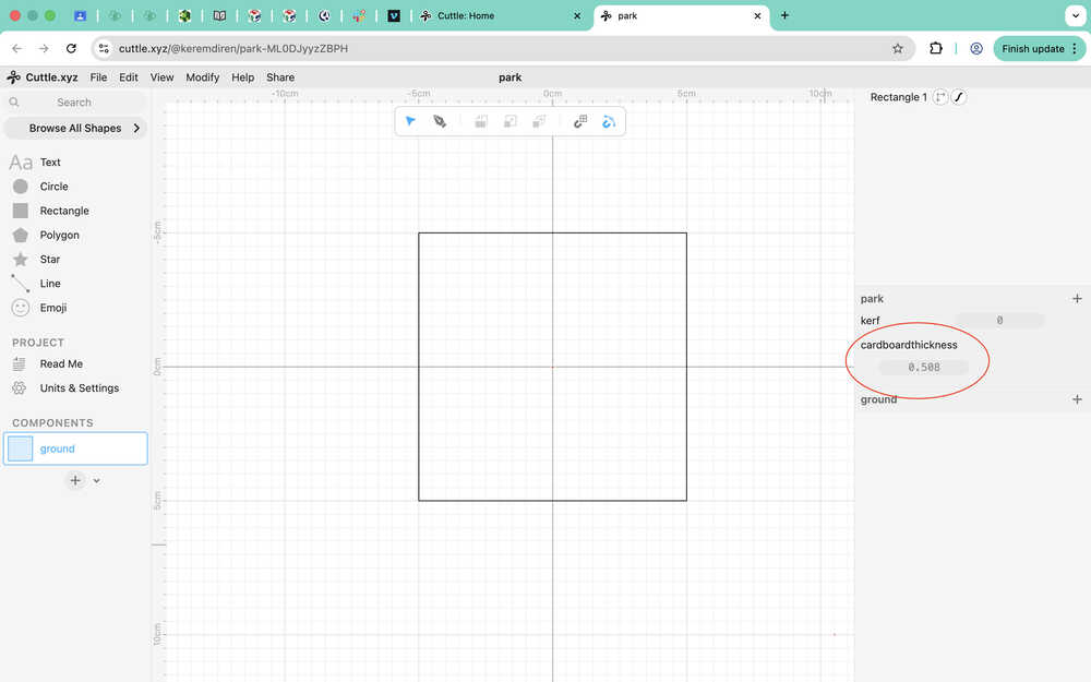
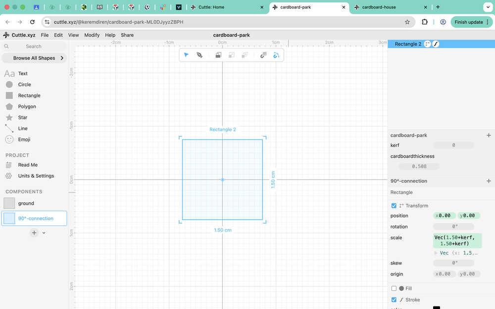
As you can see, I started with creating a ground component. I created a 10+kerf cm by 10+kerf cm square and created a parameter called kerf that I'll input to variables. I'll set it to something other than 0 after I learn the kerf of the machine the the Fab Lab at Hisar.

I also created a parameter named cardboardthickness. I did this because I wasn't 100% sure that the thickness of the cardboard at the lab was 5.08mm.
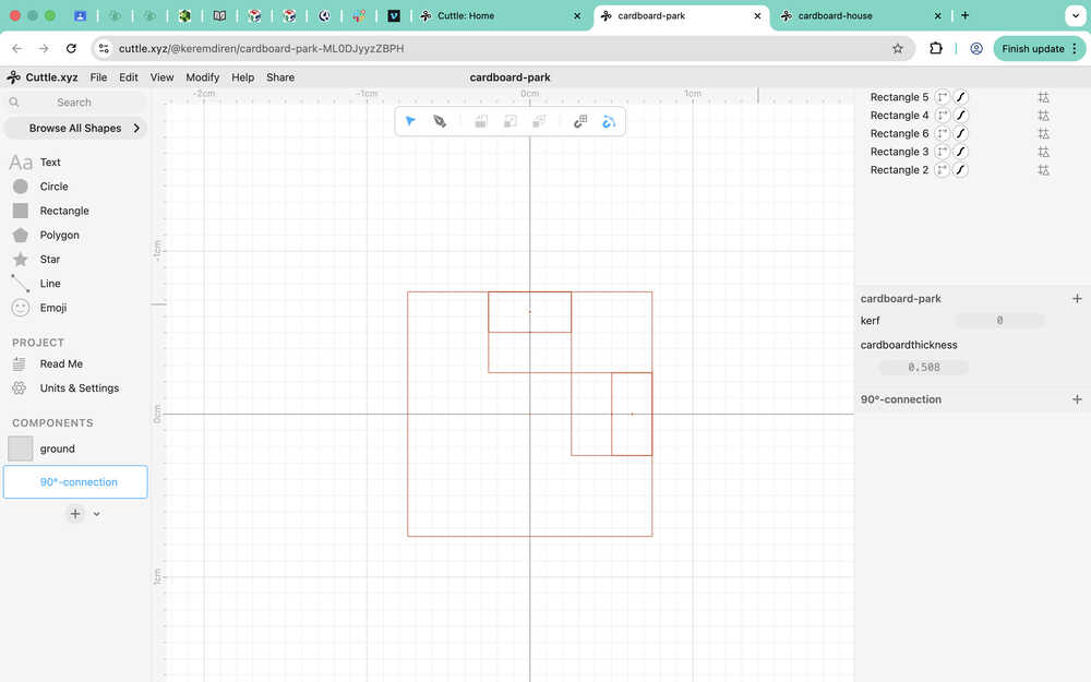
I created the base of the connection.
I used these as guides to create the component. The small rectangle has size (0.508, 0.496/2), while the big one has size (0.508, 0.496).
I will now input the parameters to the component so that it changes according to the parameters.
I made it so that these four anchors increase outwards when cardboardthickness increases. I used the equation (±cardboardthickness ± 0.254).
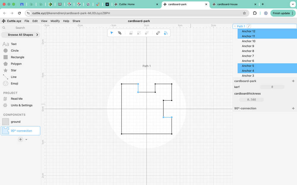
For these three anchors, I used (±0.75 ± cardboardthickness ± 0.508) on the dimension I want to scale.
How they scale:
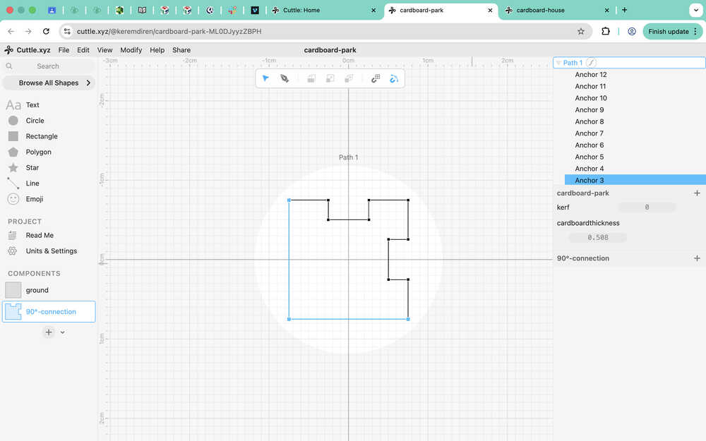
Now, I'll be working on adding kerf into these equations.
I made it so that the component scales outward whenever kerf increases.
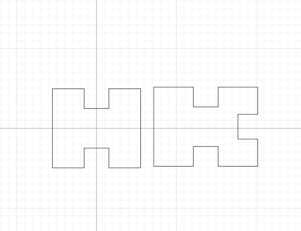
I will use two 90 degree connection components to create the 90°-90°-connection component.
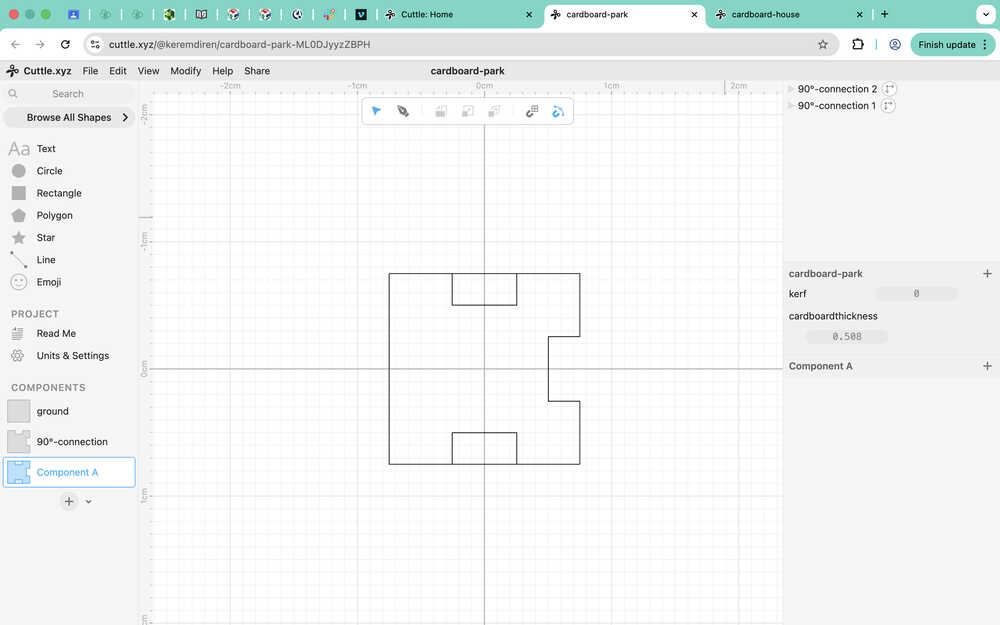
I created two copies of the path inside the 90°-connection component so that, when I edit the ones in 90°-90°-connection, the base 90°-connection components doesn't change. This way, I can still keep the equations I used (I don't have to write them again).
After testing, I learned that scaling with kerf still worked; however, scaling with cardboardthickness didn't work.
For one of the paths, I deleted every anchor except the ones that created the bottom connection part itself.
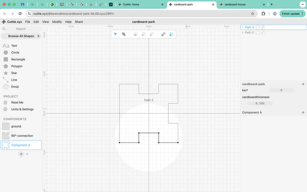
Then, I made it so that its y position value changes with cardboardthickness.
How it scales now:
I did the same for the 180°-connection component. I took two paths and deleted some parts.
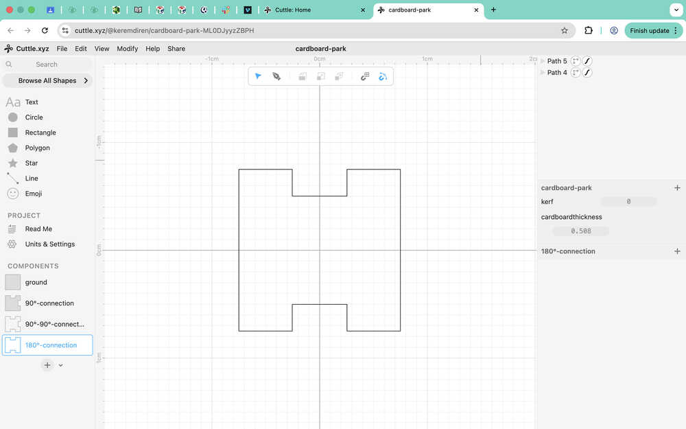
Because the two paths scale from opposite sides, I have to change it so that they scale equally in the two directions.
The equations for the position of the anchors are now (-cardboardthickness/2+kerf, -0.502-kerf), (0.75 + cardboardthickness - 0.508 + kerf, -0.75 - kerf), or ones similar to these.
The connection component scaling:
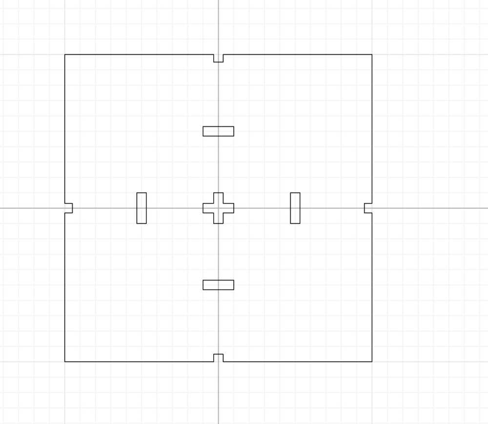
I created guides using the 180°-connection component and used the pen to make the ground/wall component.
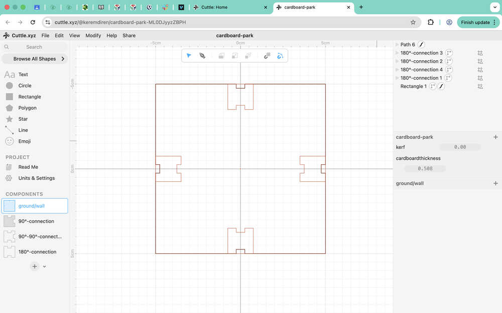
I edited the anchor points to make this component scalable.
I created five holes in the middle to make some space that can have trees, people etc. stick on. I also converted four of the rectangle holes to paths from the edit menu.
I made it so that, using the kerf and cardboardthickness parameters, the holes can be scaled as well.
I created a component named door and put the ground/wall component in it.
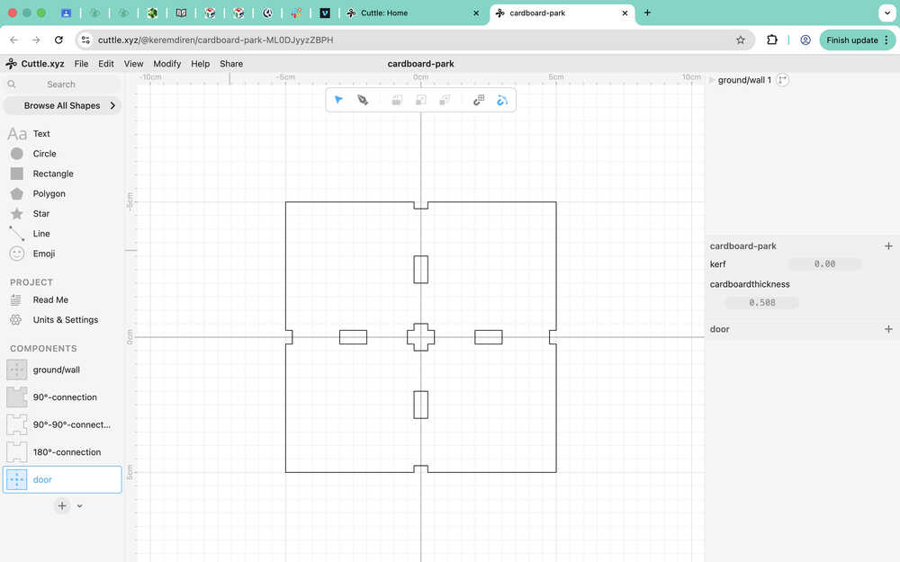
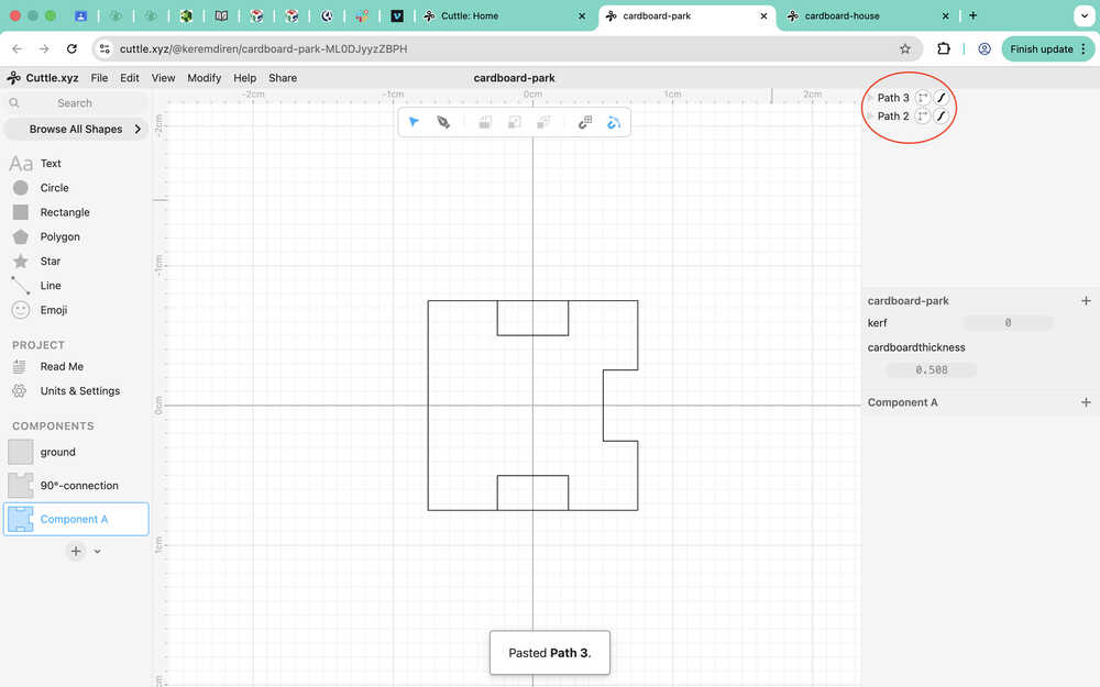
I copied the path that made up the cover of the ground/wall component and pasted it.
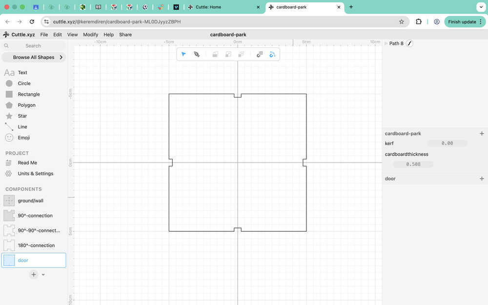
I created a door shaped path using the pen and merged it with the other path by dragging it into the it. I also had to put it between the correct anchors to make it so that the path goes on correctly.
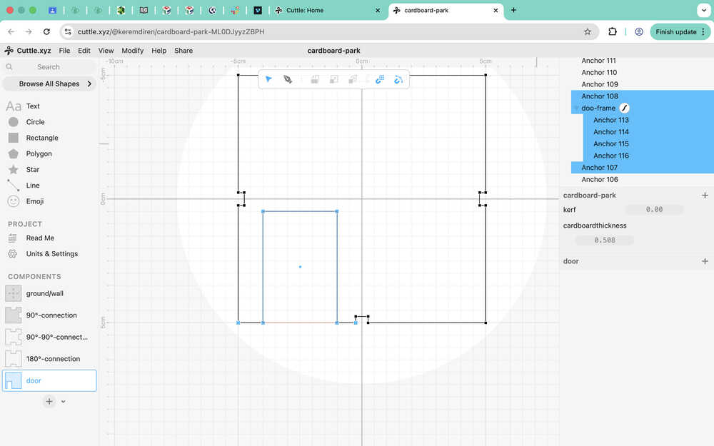
I basically added four anchors to the previous path.
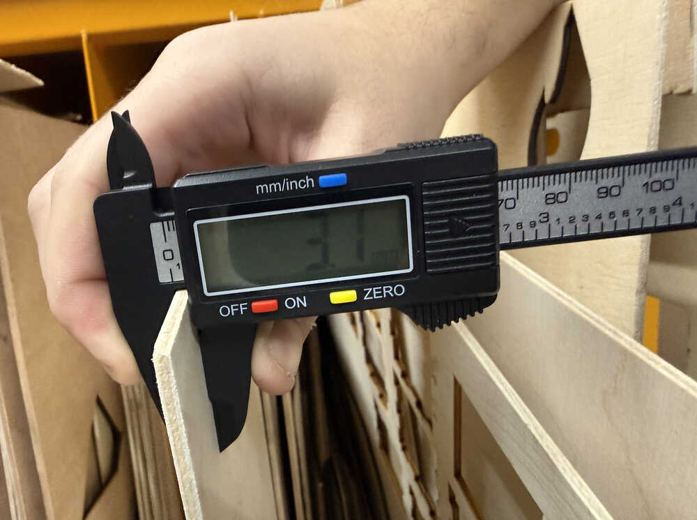
I decided to use wood instead of cardboard, so I measured the thickness of the material and changed the value of the cardboardthickness parameter (not the name, though).
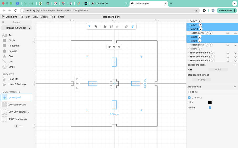
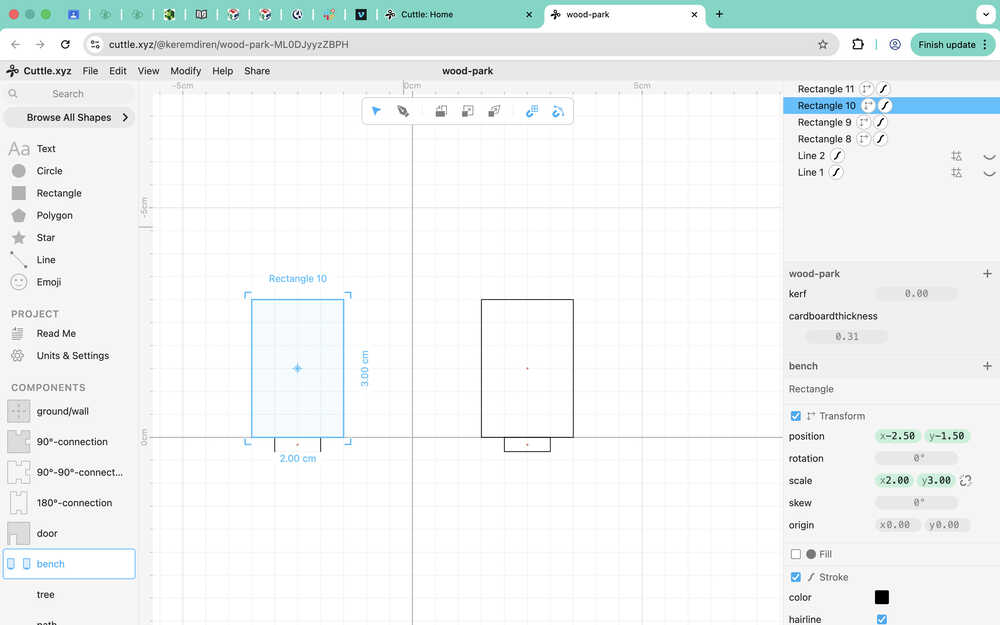
I first measured the distance between the two holes of the ground/wall component. The legs of the bench will be inserted there.
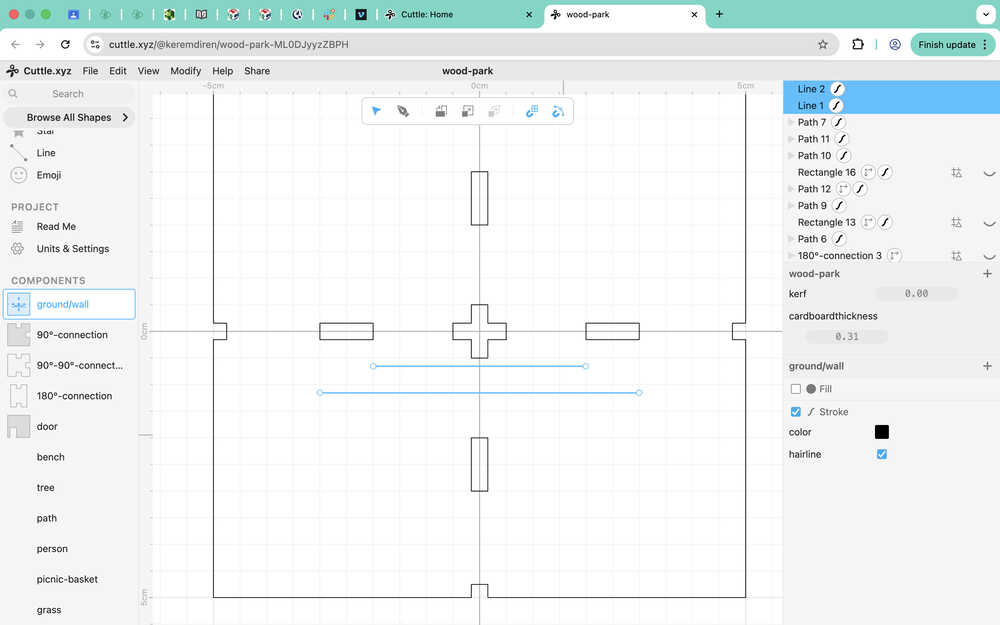
The values were 4cm for the smaller line, and 6cm for the longer line.
Using the lines, I created two rectangles that I'll use to connect the bench to the ground. They have a height of cardboardthickness.
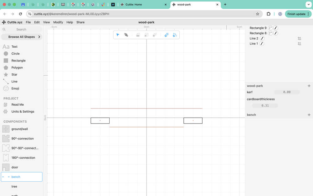
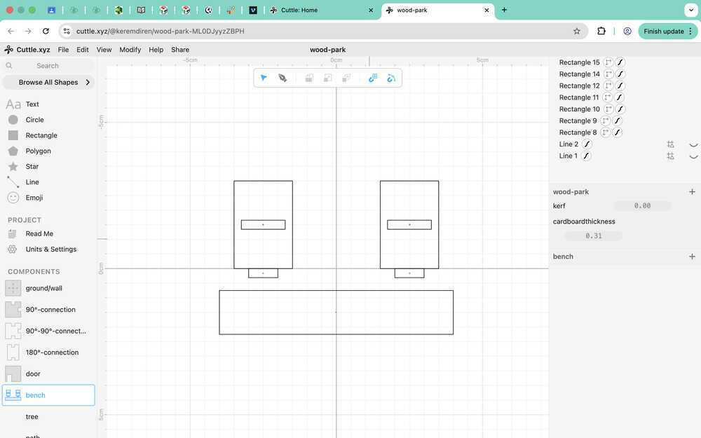
I created two rectangles that I'll use as the sides of the bench.
I created the sitting part of the bench and holes in the sides of the bench that'll fit into the sitting part. The holes are 1.5cm by cardboardthickness; the sitting part is 1.5cm by 8cm. I made the sitting part a bit wider to give it extra space to hold onto the sides.
I created the back of the bench and two more holes for the back. The holes are 1.2 by cardboardthickness and the back is 2 by 8 (I wanted to give it extra height to make it taller than the sides).

I used pen on the sides:
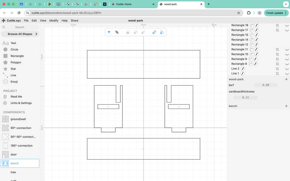
I turned the bottom and the back of the bench to paths. I also gave the bench component the parameter kerf and cardboardthickness (to the parts they weren't and needed to be present). This is how the parts of the bench component scales:
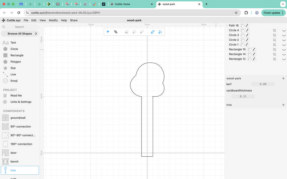
I created guides for the tree component. The leaves will be made by engraving.
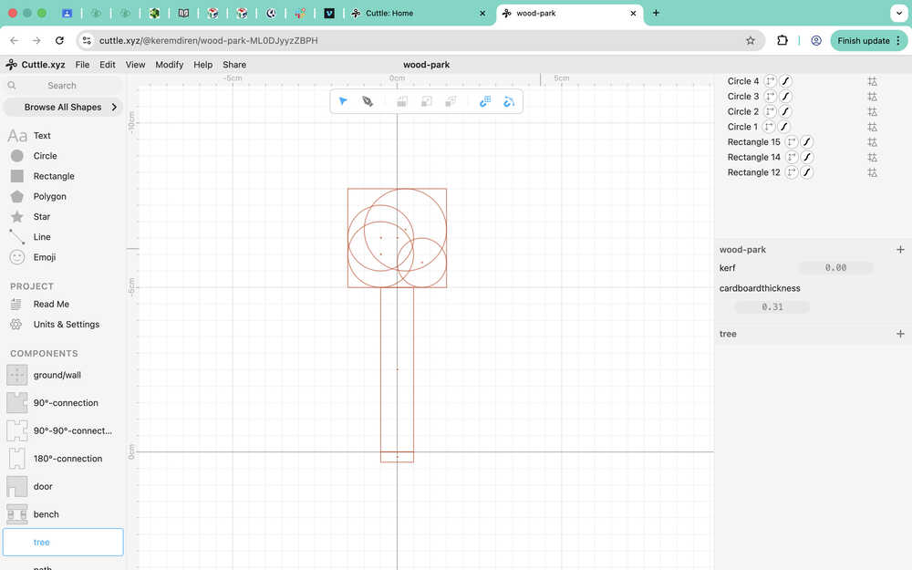
Because I was able to do the curves with the pen, I decided to not engrave the trees leaves. I also added kerf.
I separated the wall component from the ground component because I don't want my walls to have holes.
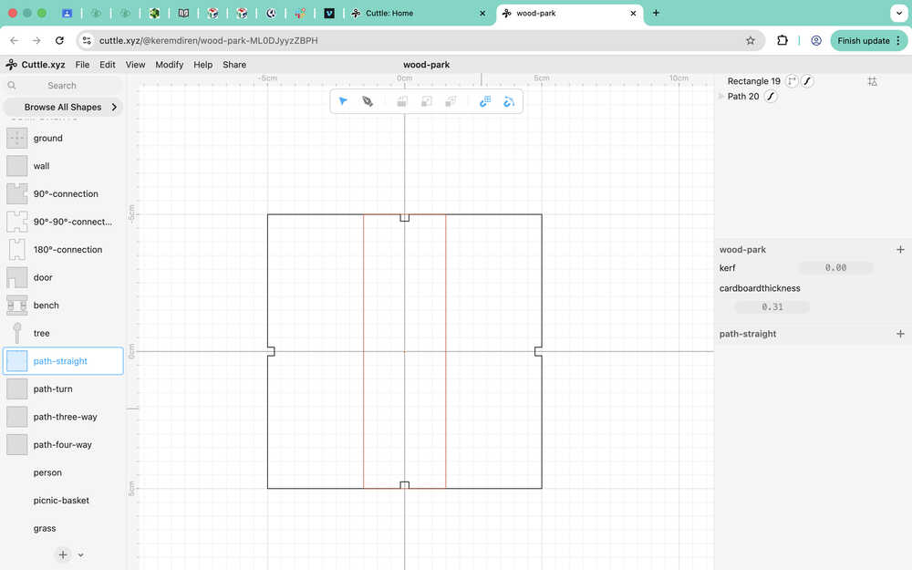
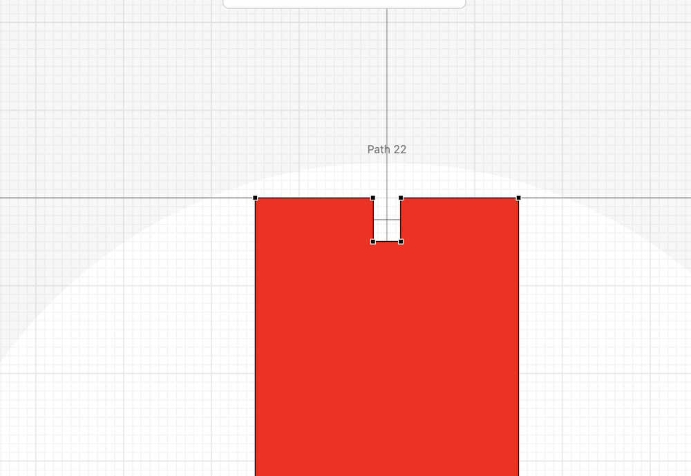
I will be creating four different paths. The paths are separated into these types: straight, turn, three-way, and four-way. I created a guide to make space for engraving since I want to engrave the path part.
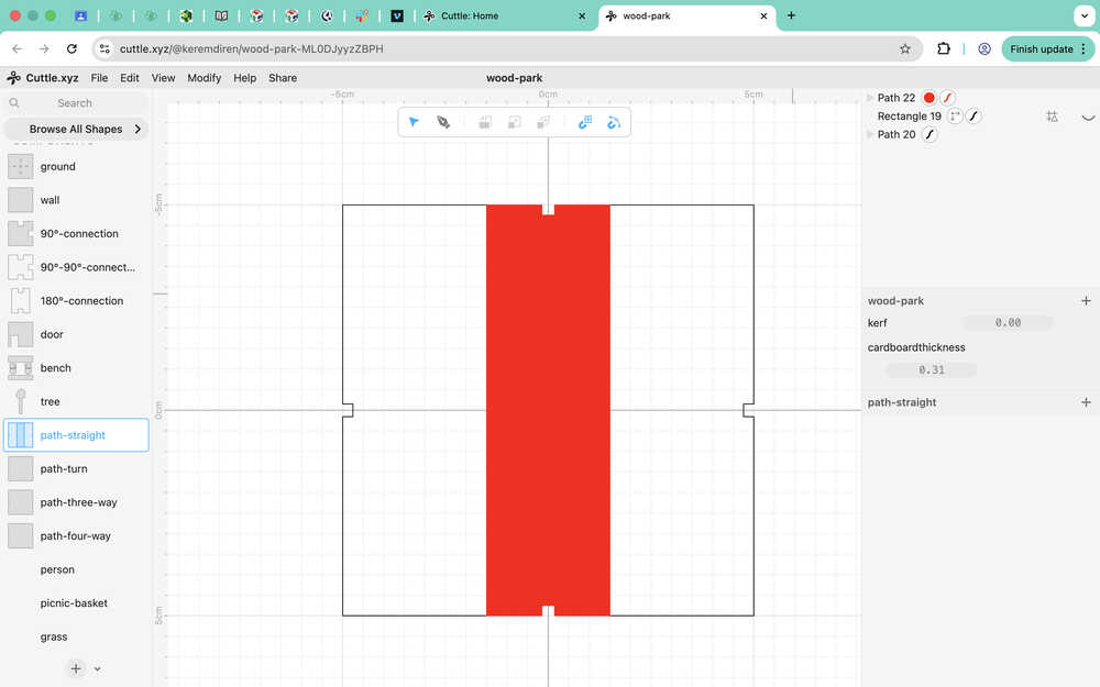
This is the part that'll be engraved. I introduced the cardboardthickness parameter to it. However, I didn't use kerf on it since it's engraving, so there isn't much kerf and it doesn't really matter. I made it red because I believe making it a different color makes it possible to do different actions with just one file.
I repeated the same procedure for the other three types of path.
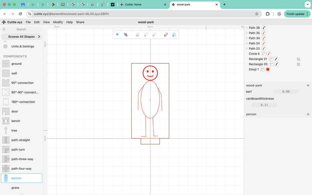
I created the person component.
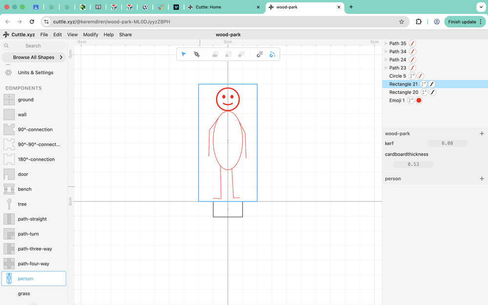
Using pen, I went over the guides. I also integrated both of the parameters to the person component.
I repeated the same for the grass component except that I also used fill on the inside of the grass component.
Lazer Cutting My Design
Final Version
Number of Parts Needed
- 1 path-four-way
- 1 path-three-way
- 5 path-straight
- 2 bench
- 8 ground
- 4 wall
- 18 tree
- 12 grass
- 3 person
- 9 90°-connection
- 3 90°-90°-connection
- 19 180°-connection
- 1 door
Measuring Kerf
I first created a 1cm by 1cm square in Cuttle and sent it to the lab's computer along with my files for my design.
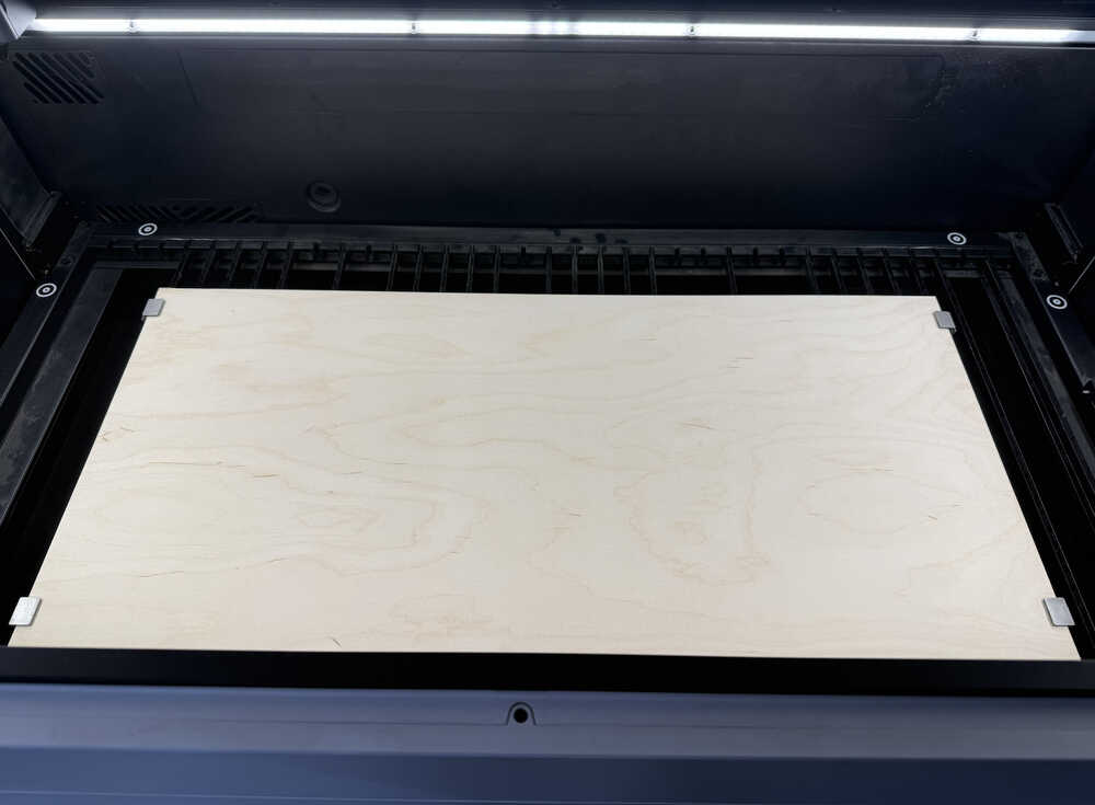
I put the wood inside the machine.
I imported my three of my testing squares. Also, because auto-mode was on, the background refreshed and the distance calculated automatically.
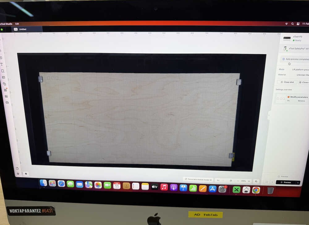
I set the power to 80 and speed to 32. Then, I clicked "process" and started the machine.
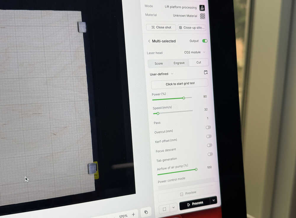
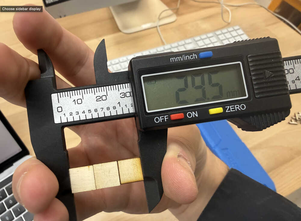
Video of the machine cutting:
The length of the three squares next to each other should have been 30mm; however, it was 29.5mm. This means that the kerf is about 0.5 / 6 = 0.083333mm.
Cutting
I first updated the kerf value of my design and sent it to the lab's computer.
I was going to cut the connections first with 80 power and 32 speed; however, as it was cutting, I saw some fire. I stopped the machine. The fire didn't continue; however, I decided to use less power. I continued with measuring the kerf with less power.
I decreased the power to 60; however, the wood didn't get cut.
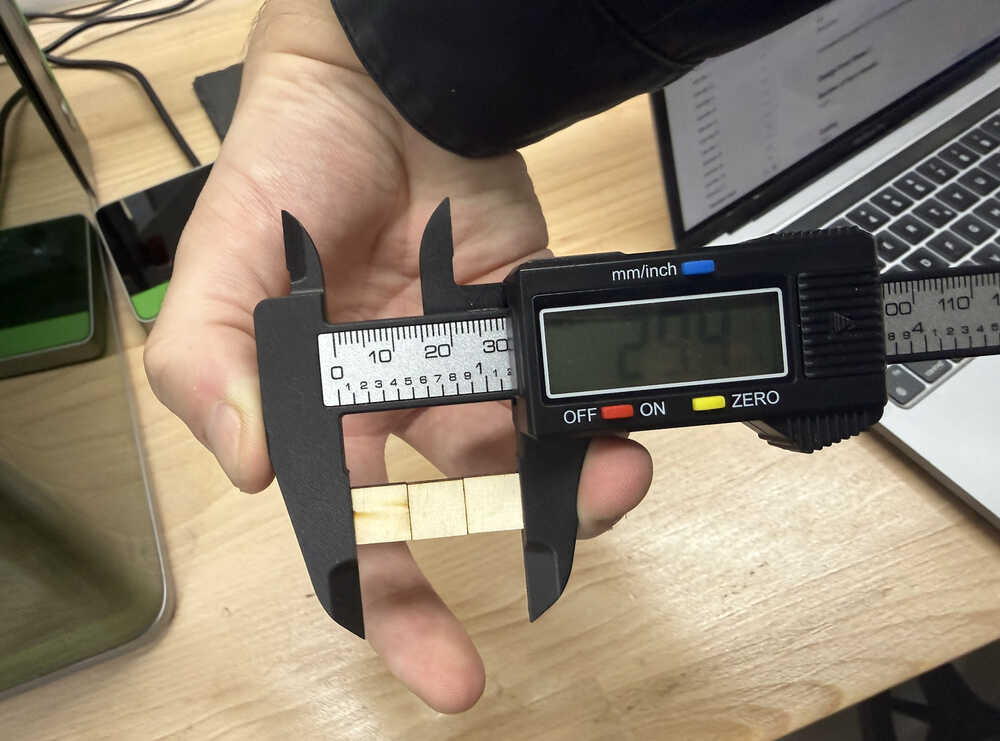
I increased the power to 65 and decreased the speed to 26. Only two of the three squares got cut.
I increased the power to 70. This time it worked well. The kerf is now 0.1mm.
I updated the Cuttle design and sent it to the lab's computer again.
Cutting:
Engraving:
I used 34 power and 200 speed for engraving and scoring.
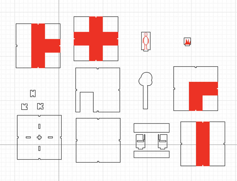
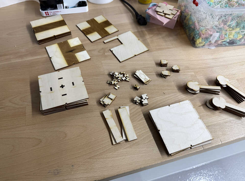
The components:
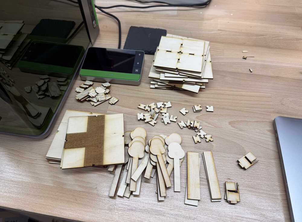
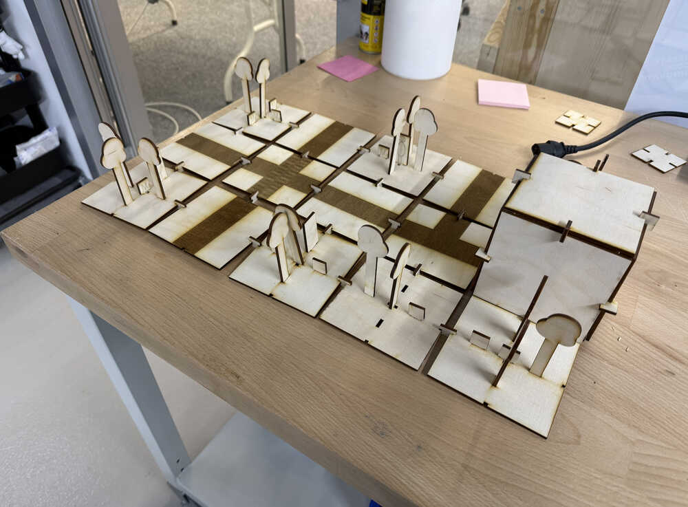
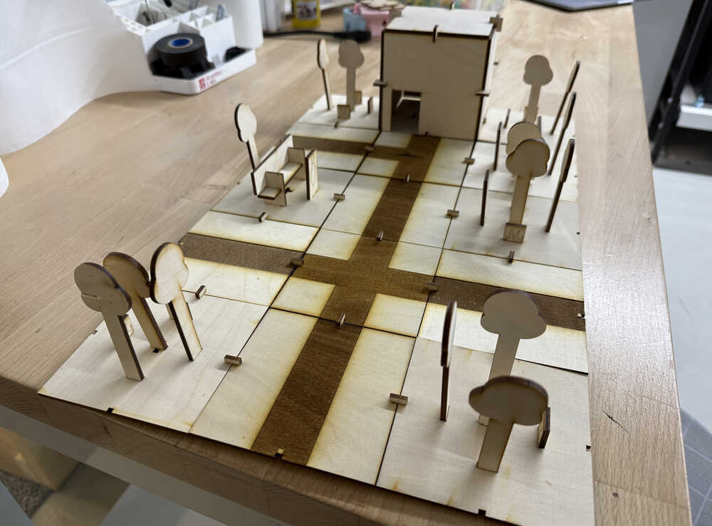
Assembling:
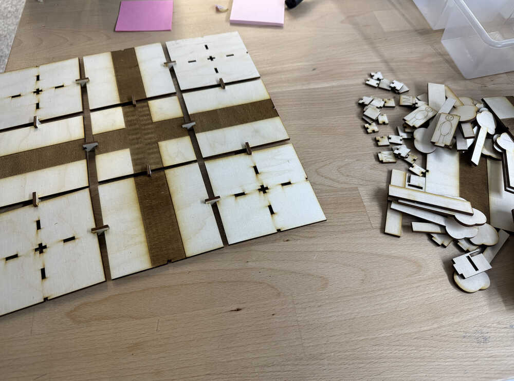
The 180°-connection component is longer than I intended, which is why the ground tiles have space between them; the 90°-90°-connection component also could have been better, but it does the job, so it's okay. Also, because the holes in the middle part of the ground component is turned in the wrong direction, I couldn't fit the bench to the slots. Also, because of the engraving, the connection from other components to the engraved part of the path components is unstable.
Files
You can find the files here. The kerf value of these files are set to zero.
Post-Week
I changed some parameters in a way that'll stop the middle part of the connection after the thing is connected.
I turned the holes by 90 degree.
I realized that the 90°-90°-connection component still has a problem after you change the thickness of the material. That's why I changed some parameters. This is how it scales now.
I decreased the size of the end of the paths that connects to the connections by 0.248cm. This way, the connection part wouldn't fall off so easily from the path.
The parts are ready:
After it's assembled:
This time, while extracting my files, I forgot to set the kerf parameter to something that's not zero, which is why the connections between components are still kind of fragile; however, this time, the design itself is correct.