Week 2, Computer-Aided Design
Table of Contents
- Overview
- Resources
- Inkscape
- Illustrator
- Photoshop
- Cuttle
- Fusion
- Onshape
- Blender
- Compressing Image and Video Files
- Files
Overview
In this week, I used many design programs (vector, raster, 3D, 2D) and animated a 3D design I made. I also showed how images and videos can be compressed. I also tested a little parametric design while doing my Fusion 360 design.
Resources
- I used Blender.
- I watched this tutorial to learn Blender.
- I watched this tutorial to learn Blender animation.
- I used this link to learn how to input videos into HTML.
- I used iMovie.
- I used Adobe Photoshop.
- I used Image Magick.
- I used Adobe Illustrator.
- This is where I learned about Adobe Illustrator.
- I used Cuttle (great site).
- This is the tutorial video I watched to learn Cuttle.
- This is Ms. Nadieh Bremer's documentation that I peeked at for my design in Cuttle.
- I used Onshape.
- This is where I learned Onshape.
- I used Fusion 360.
- This is the tutorial video I watched to learn Fusion 360.
- This is where I learned about joints in Fusion 360 (although I didn't use them).
Inkscape
Design Goal
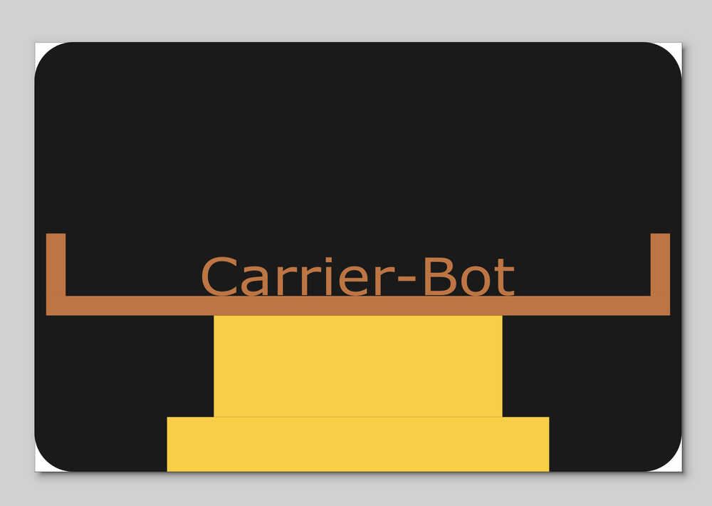
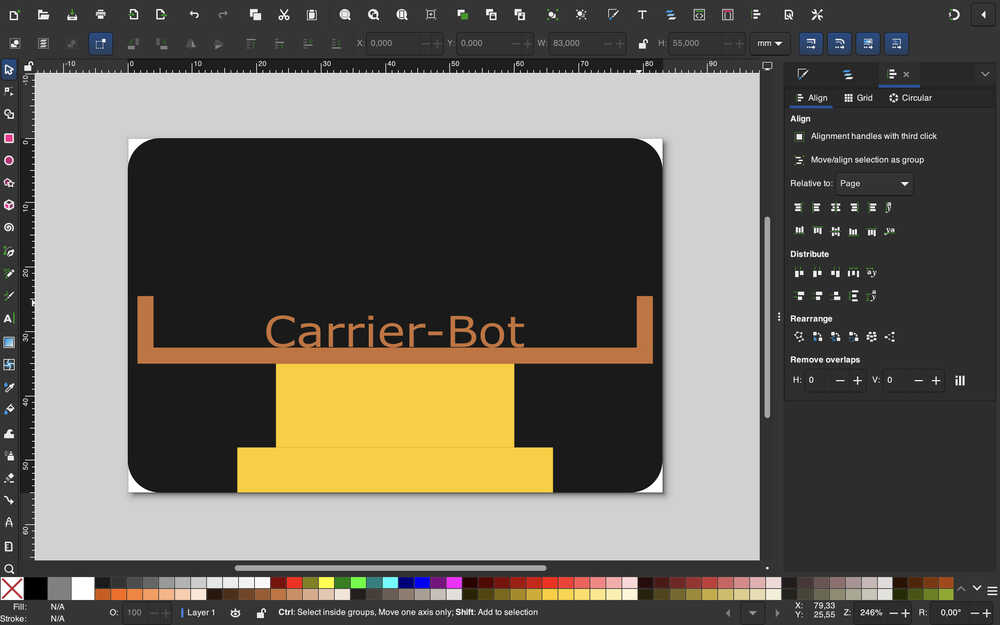
I'm planning on creating a sticker for my final project. On the sticker, I want the main focus to be the carrying part of the bot I'll produce, with only some of its middle part being showing.
Final Version
Design Process
I downloaded Inkscape from the link I provided above.
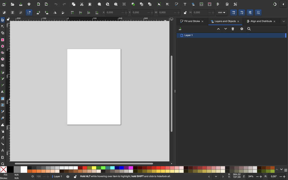
I opened the program and clicked to the button at the bottom right corner to open a new project.
I'm using mm as size units.
I created a rectangle using the rectangle tool. Then, I set its position to (0,0) and gave it 83mm width and 55mm height.
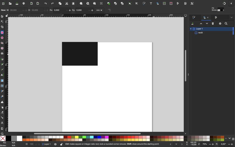
I softened the edges by first clicking on the rectangle while the rectangle tool is equipped, then by selecting the Rx parameter and giving it the value 5mm.
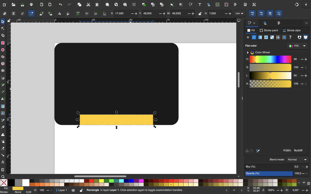
I created another rectangle and gave it appropriate values to represent some of the middle part of the bot.
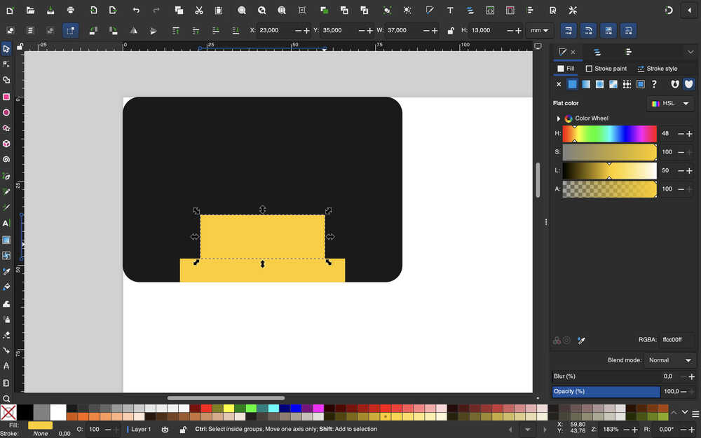
I created another rectangle to represent the upper middle part of the bot, this time slimmer and taller.
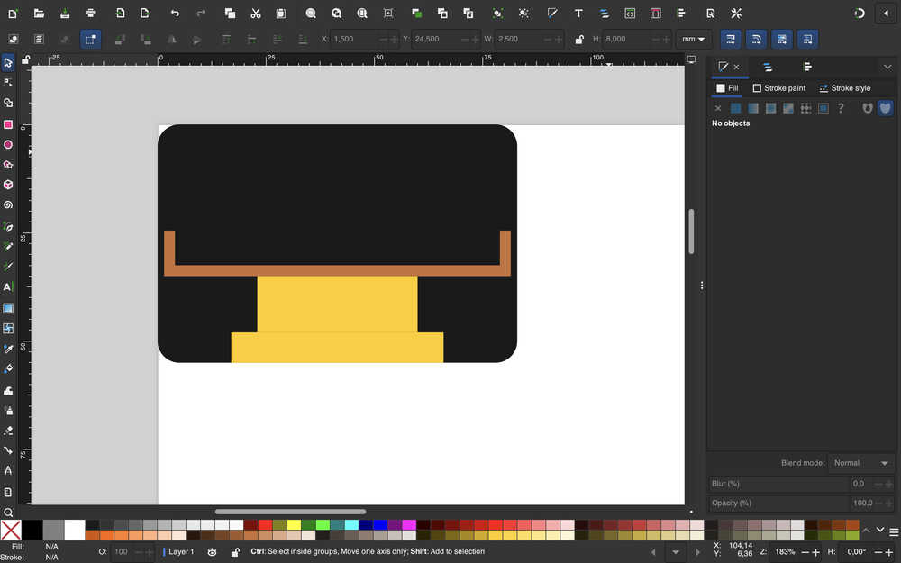
I created three more rectangles to represent the upper (carrying) part of the bot.
I grouped the parts and named them accordingly.
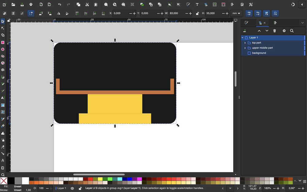
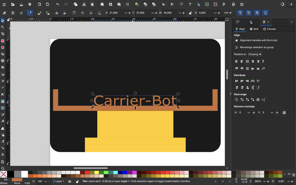
I used the text tool to create a text and wrote "Carrier-Bot" in it. I determined its y value with some calculations. I also aligned it to the middle of the design and renamed it to "name".
I used "resize page to selection" from the help menu.
Tools Used
Rectangle Tool
You can create a rectangle while this tool is selected. You can also soften the edges of a square while this tool is selected.
Text Tool
After selecting this tool, you can write text to anywhere and edit the text's looks and properties.
Grouping
You can group elements by selecting the target elements and clicking the group button. This does something similar to merging them. When you click one, both are selected, but you can still edit them individually if you want.
Illustrator
Design Goal
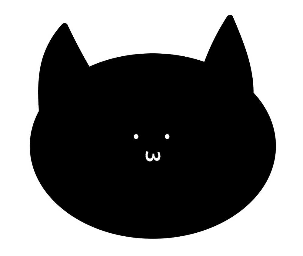
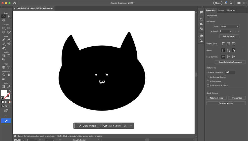
I want to design a simple cat face in Illustrator. I want it to be black with a small, white face.
Final Version
Design Process
I opened a new project in illustrator.
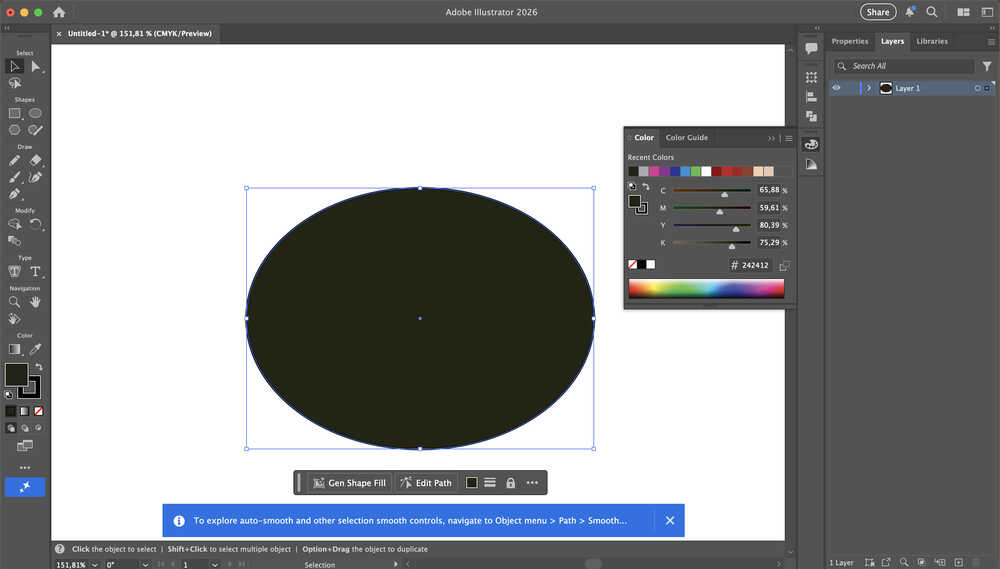
I started with creating an oval shape for the head. I used the ellipse tool.
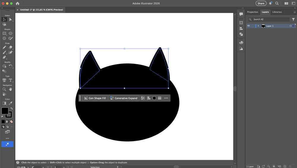
Using the paintbrush tool, I drew two ears.
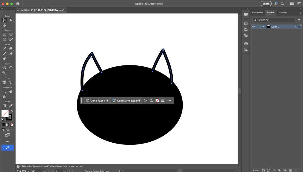
I selected the ears and selected "join path" to get the ability to fill the ears with black color. Then, I made the ears black.
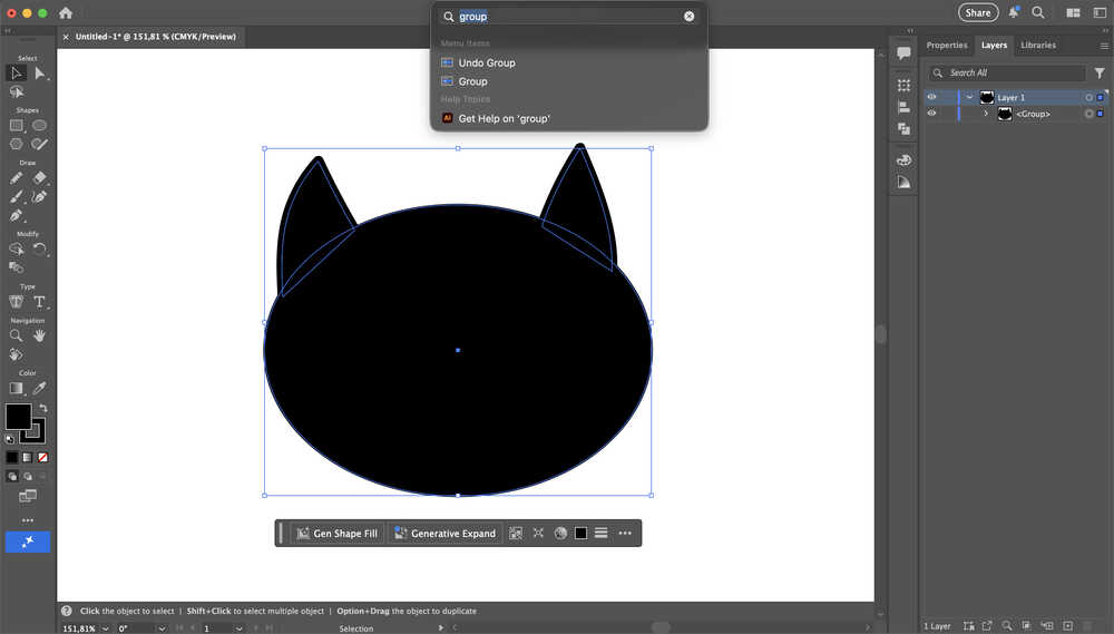
I grouped the parts by using "group" in the help menu.
I clicked a button at the bottom right corner of my screen to add a layer to put the face at.
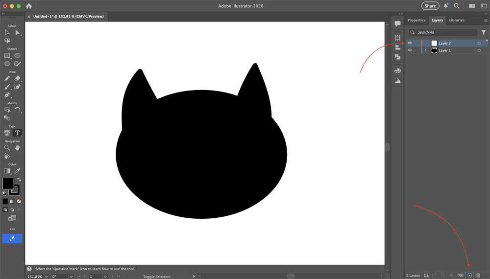
I created and grouped the face. I also named the two layer "head" and "face".
Tools Used
Ellipse
You can create an ellipse while this tool is selected.
Paintbrush
You can draw things while this tool is equipped, after which you can fill the inside of if you want to.
Group
You can group different elements together, which basically merges them, although merging and grouping aren't exactly the same.
Photoshop
Design Goal
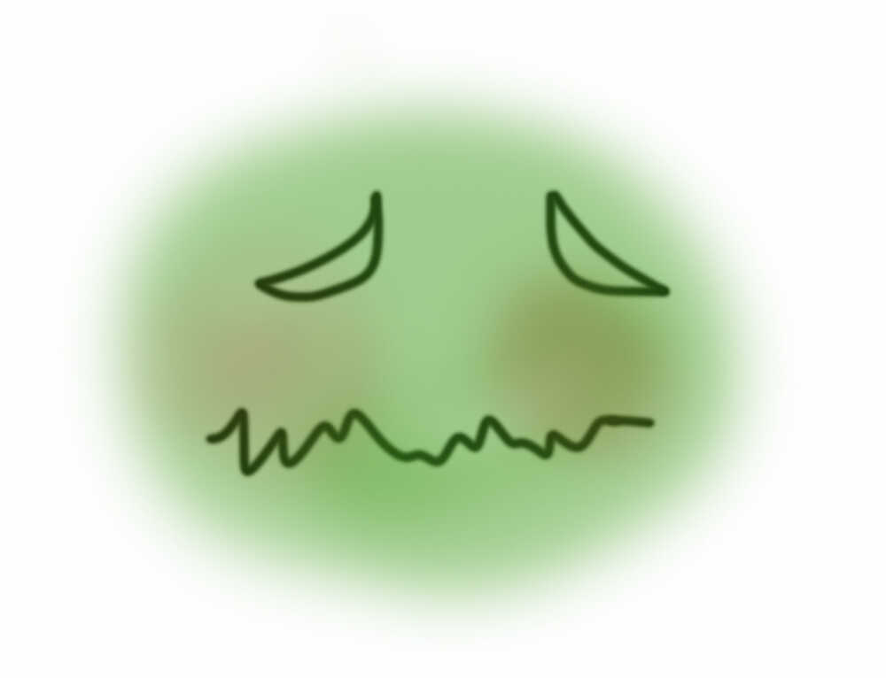
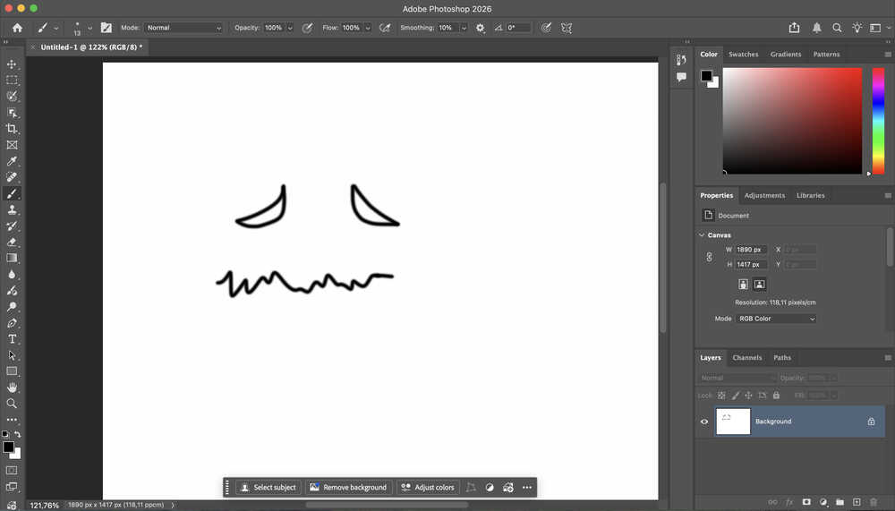
I made a weird face in this design.
Final Version
Design Process
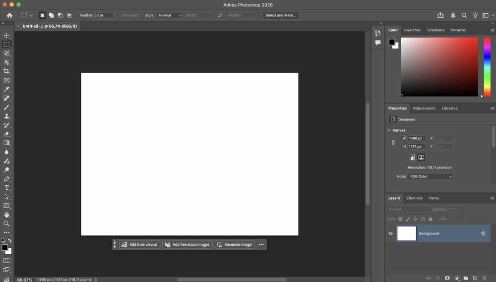
I opened up a new project.
I selected the brush tool and drew a face.
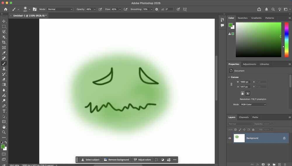
After changing the flow, opacity, and the brush's size, I turned the face green.
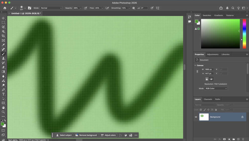
Unlike a vector design program, we can see the pixels in this program.
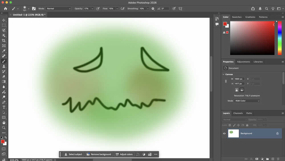
After decreasing the size, opacity, and flow, I added a red tint to the cheeks of the face.
Tools Used
Brush Tool
You can draw using this tool. You can also change the properties (opacity, size, flow etc.) of this tool to make different kinds of effects.
Cuttle
First Design
Design Goal
I will be creating the carrier part of my final project. I want to make it so that the carrier part can be detached from the main body.
Final Version
Design Process
Through this design, as you will see, I gave extra length to some parts. I want to mention that every length I set is intentional and calculated. Some are longer than what they need to be because I wanted to make the usage more comfortable, and because I wanted to prevent some parts from falling off when the project suffers an impact.
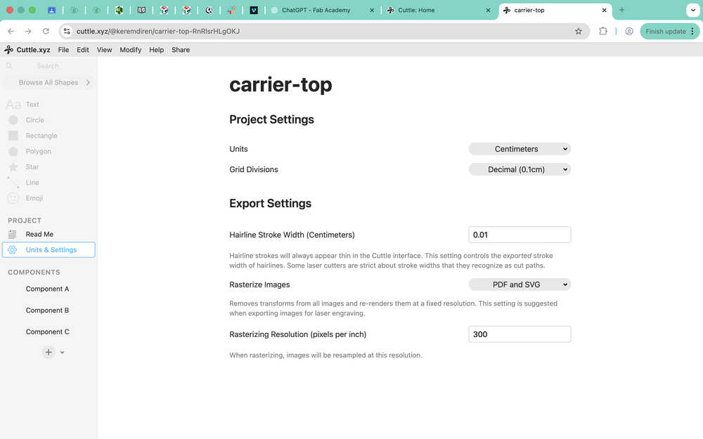
After opening a new project, I changed the units to cm.
I created three components and named them.
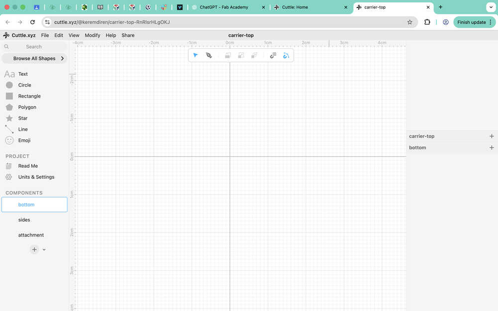
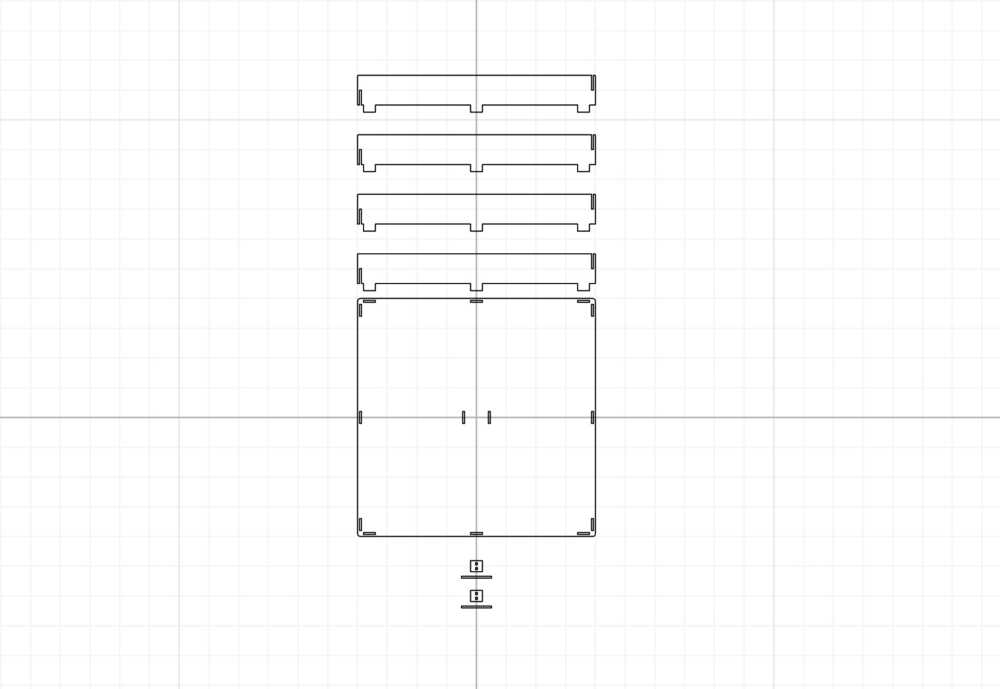
I'll create the bottom component first, which is made up of one part. I only need to use one of this component for my project.
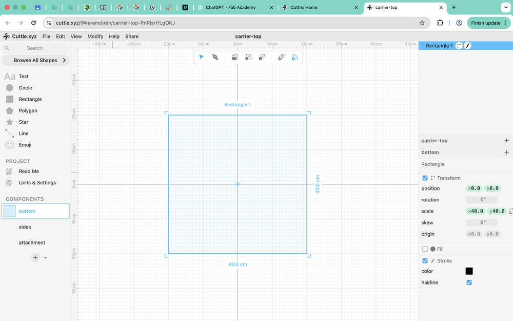
I created a square with 40cm side length.
The thickness of the material in my fab lab is 3.09mm.
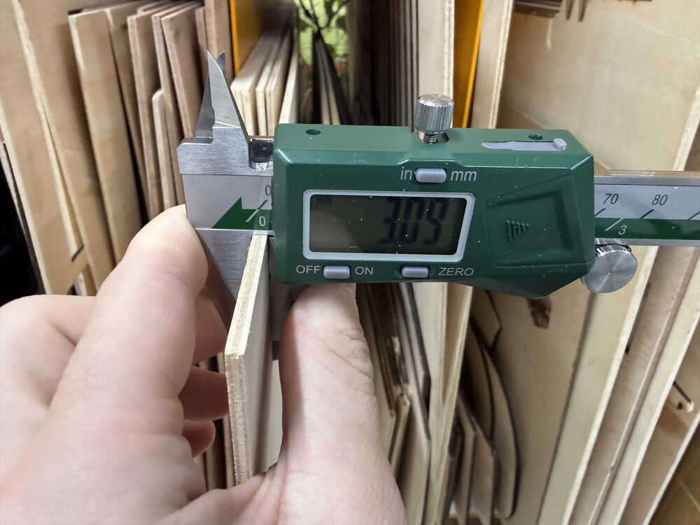
I will be leaving a tolerance of 0.11mm.
I turned the square to a guide to use it to make a square with softer edges.

I redrew the square with softer edges.
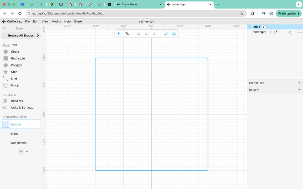
I created a part to attach the sides to the bottom. I also grouped the elements of bottom and named them. Every attachment part has a width of 3.2mm.
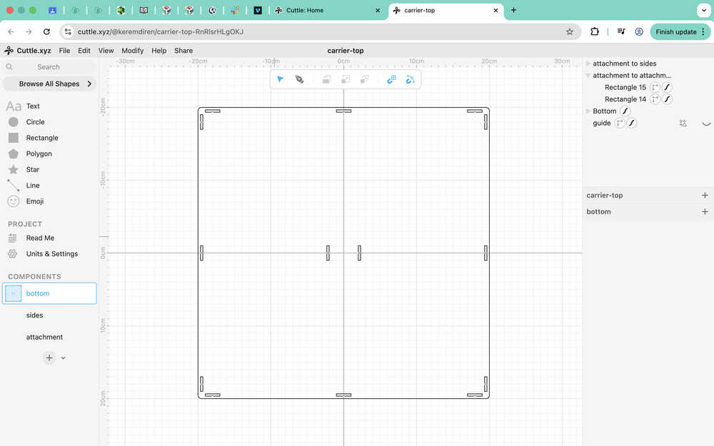
Now I'll create the sides component. This component is made up of one unique part, four of them will be used for my project.
I brought one bottom component into the sides component to help as a guide.
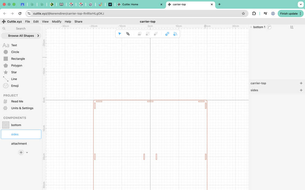
Using the bottom component as a guide, I created six rectangles to use as guides when creating the sides component. I made it so that the height of the sides will be 5cm.
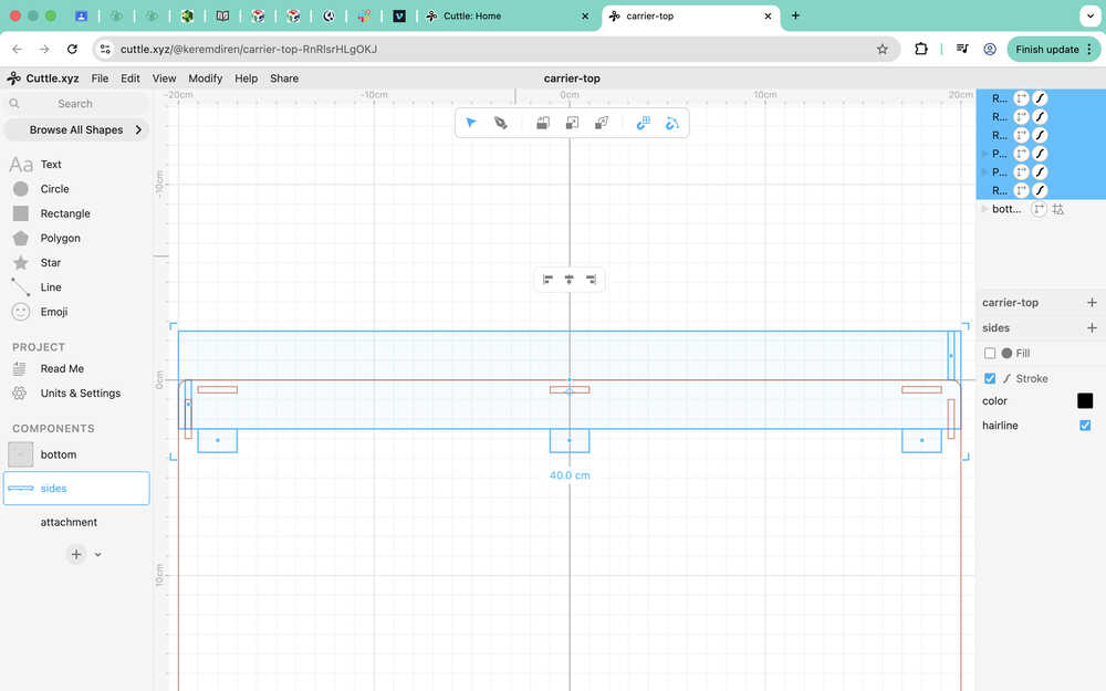
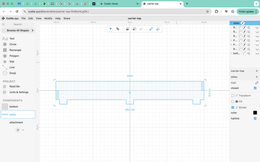
Using the pen, I created the sides component. I also gave its upper part a softer edge.
Now I'll create the attachment component. This component is made up of two unique parts; one will be named "main", and the other "holder". I will use two of each for my project.
I first put the body in the middle to use it as a guide.
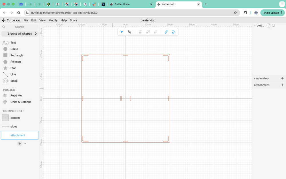
I created a guide for the main part using the guide of the body. I also made the holes the main part will have.
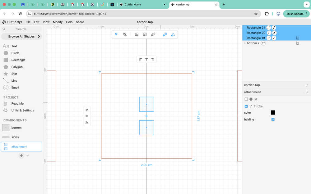
I drew the main part using the pen, grouped it, and named it.
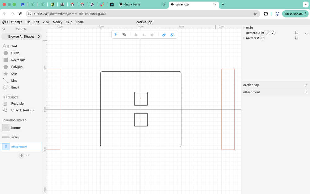
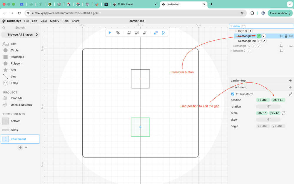
I realized the gap between the holes was too small. I meant to do it 0.509cm, but accidentally made it 0.2cm.
Using the transform button, I changed the gap to what I wanted. Final version of the main part:
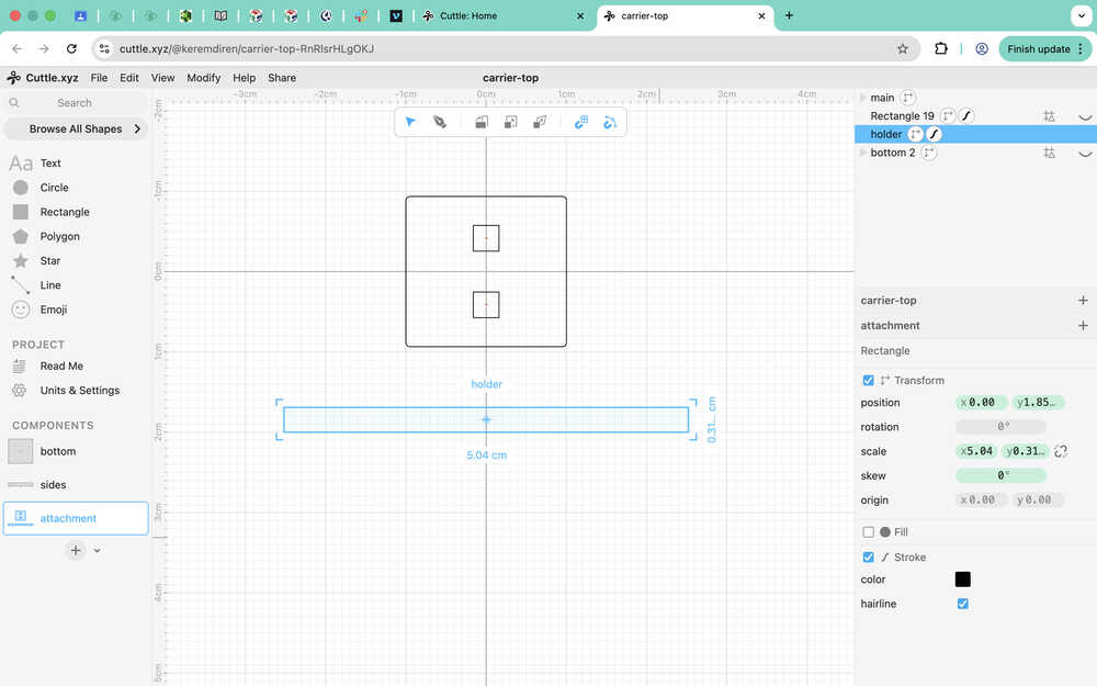
I created the holder part.
Second Design
Design Goal
I'm planning on creating a house with two floors and an attic from cardboard. In this design, I will not be using any tolerance. This is because of the squeezable property of cardboard. Of course, if I squeeze a cardboard too much, it just loses shape; however, by doing it just enough, I can make the cardboard fit into parts that it will have a hard time getting off of, which will help protect the design's shape and structure in case it suffers an impact.
I also want to mention that, for this design, I took a peek at Ms. Nadieh Bremer's week 3 documentation to learn how to connect shapes in degrees such as 120° or 60° etc. What she did also gave me the idea to design a connection part to connect three pieces.
This is the link to her week 3 documentation.
Final Version
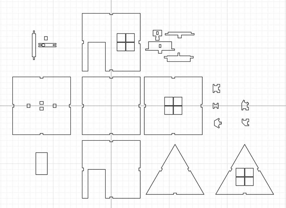
Design Process
This design will be made up of many unique parts such as wall, wall-with-window, front, back, ground, ground-with-sofa, sofa, door-connection, door, roof, attic-wall, attic-wall-with-window, connection-60°, connection-90°, connection 180°, 90°-90°-three-way-connection, and 90°-60°-three-way-connection.
First, I'll start with creating the connections. The thickness of the cardboard in my fab lab is about 0.2 inches.
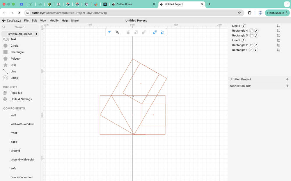
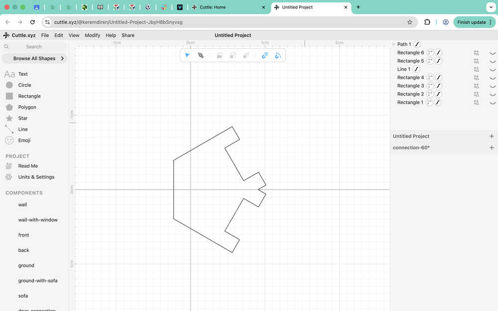
I started with creating guides for the 60 degree connection. The big rectangles in the photo will be the outer layer of the connection. The small rectangles will be the length of how much the connection will intersect the other part; their corners touch because that is how I can find the exact value to make it so that the two parts I'll connect will have no gaps in between. The rectangles' width is equal to 0.2 inches. The line is there to prevent decrease the size of the connection a little and give it a softer corner; it's 60 degrees to the horizontal.
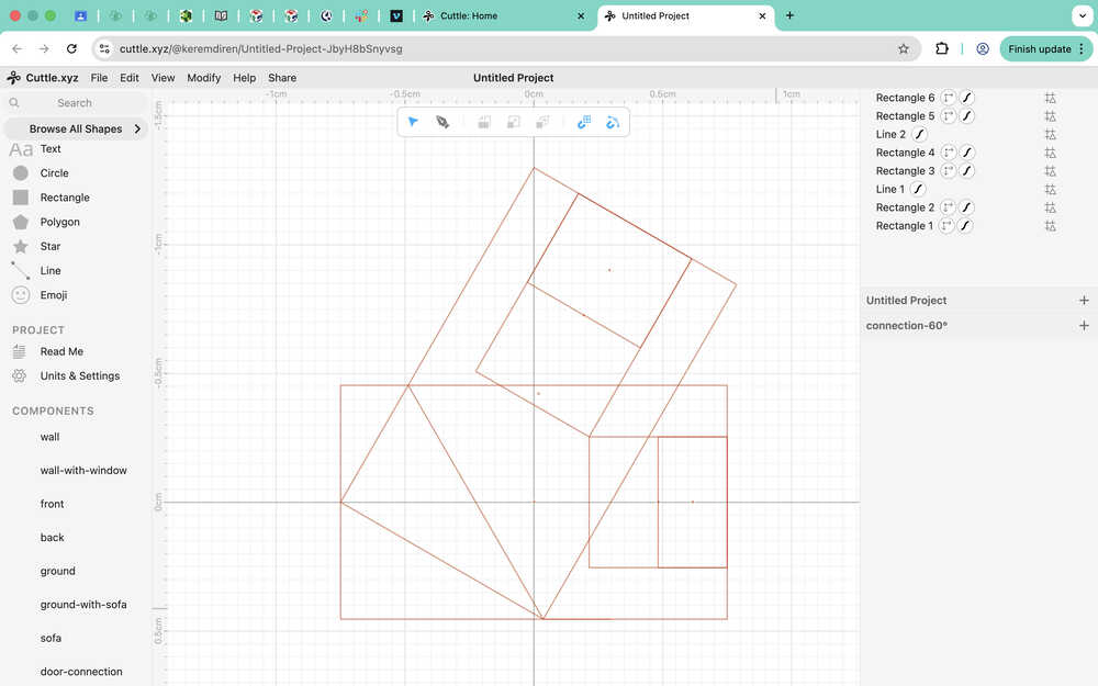
I created two more rectangles with half the length of the small rectangles. The other half of the connection will be on the part I'll connect itself. You'll be able to see it further down the documentation. The smaller horizontal rectangle has a length of 0.26791252522666253cm, and the 60 degree one has a length of 0.3989691466909844cm.
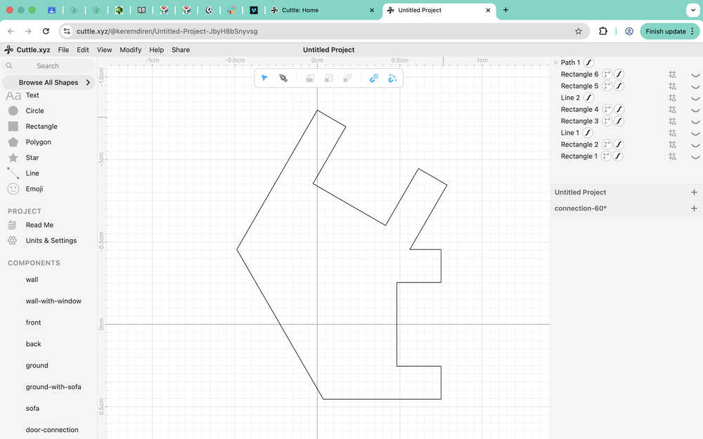
I used the pen to go over the guides.
I've realized that the two lengths (0.26791252522666253cm and 0.3989691466909844cm) had to be the same, so I redesigned the 60 degree connection.
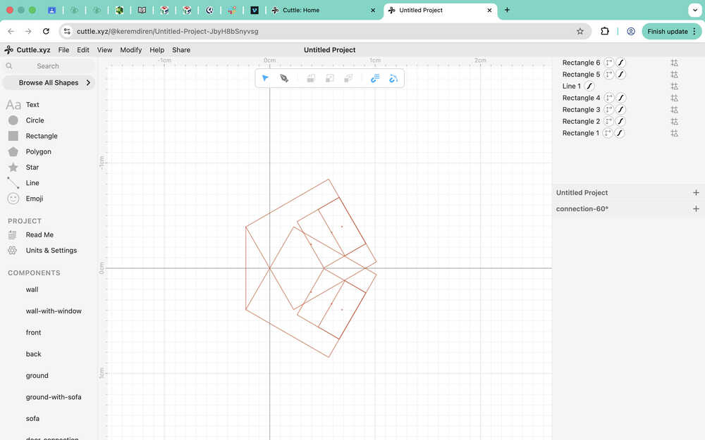
This time, I made the big rectangles a square with 0.908cm side length. The small rectangles now have 0.46158983848622465cm length and the smaller ones have 0.23079491924311227cm length.
I went over the guides with the pen.
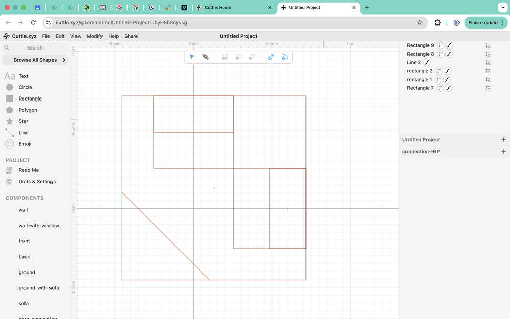
I used the length value of the small rectangle to create guides for the 90 degree connection.
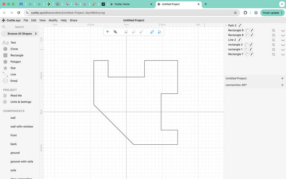
I went over it with a pen.
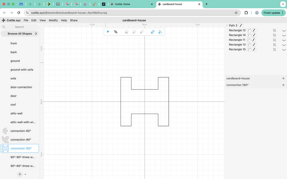
To create the 180 degree connection, I just put two rectangles with parameters 0.508cm and 0.46158983848622465cm back to back, then created a big rectangle with a width 0.908cm. Then, I create the smaller rectangles. Then, turned everything to a guide and I drew over the guides with the pen.
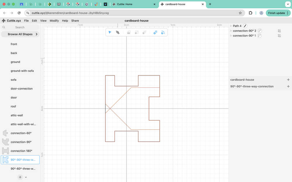
I created the 90°-90°-three-way-connection by using two 90° degree connections as guides.
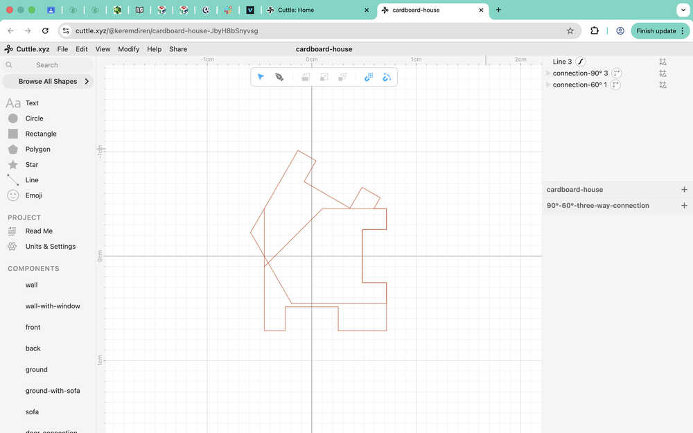
I created te guide for 90°-60°-three-way-connection by using a 90°-connection and a 60°-connection. I also added a line to make the 90°-60°-three-way-connection smoother after I go over it with a pen.
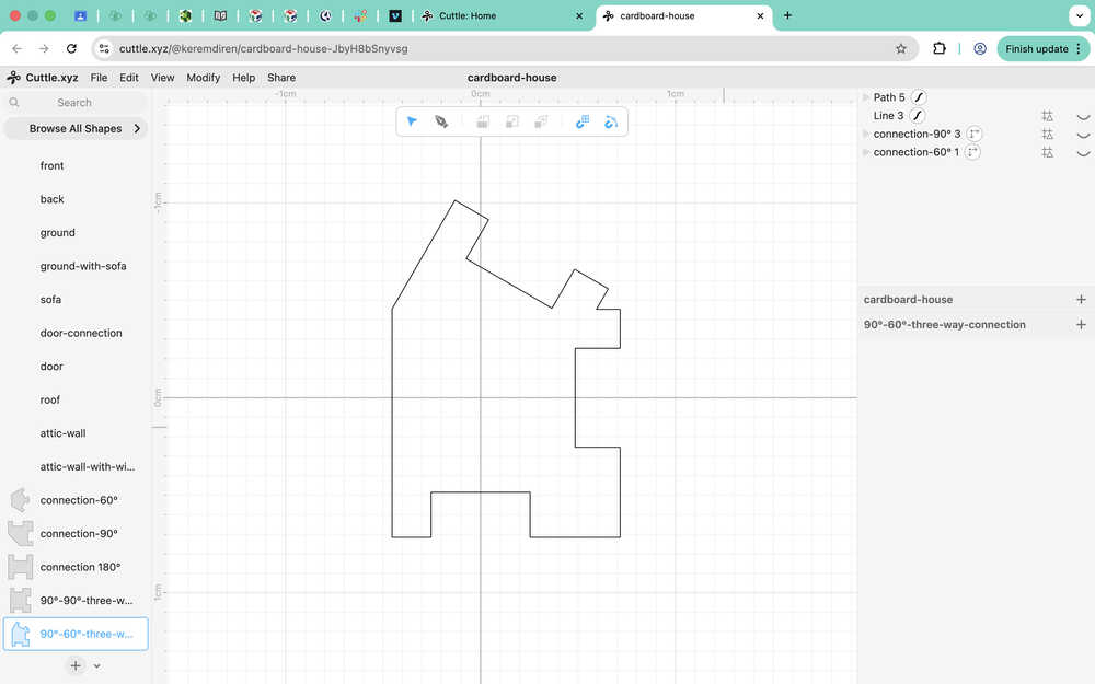
I went over the guides with a pen.
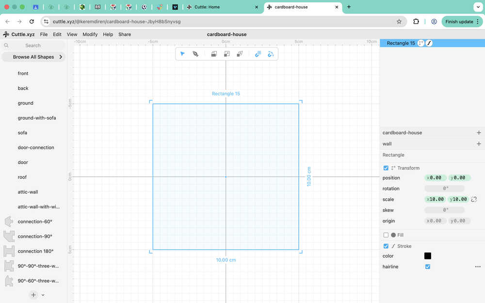
Now I'll start to create the wall etc.
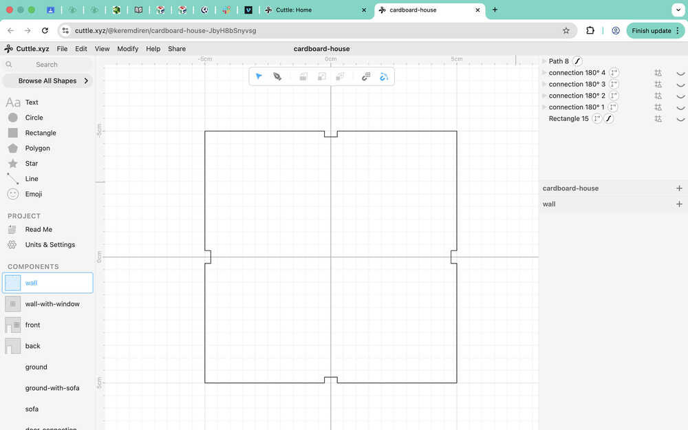
I decided to make the wall 10cm by 10cm, although I'm planning on making the house wider than 10cm, which is why I created the 180°-connection.
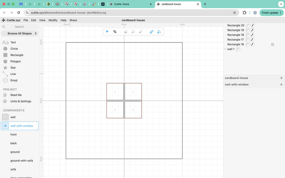
For the wall-with-window component, I created a 3cm by 3cm window with a 0.1cm thickness, cross-shaped window frame being in the middle. I also the the wall component for it.
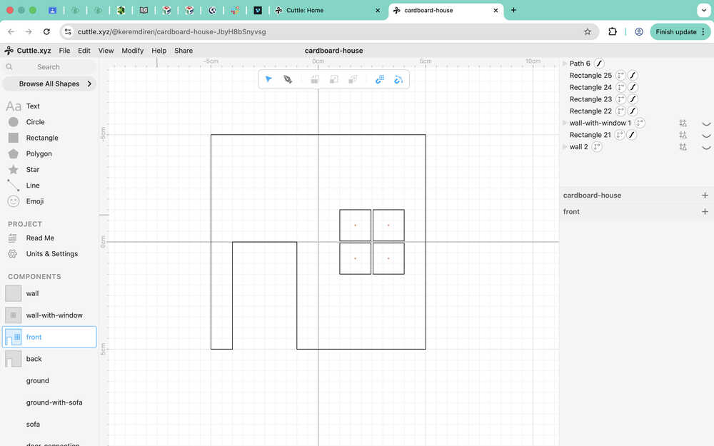
I made the a door frame for the front, which is 3cm by 5cm big. I also created put a window to the front component. I also used the wall-with-window and wall components as guides while doing this.
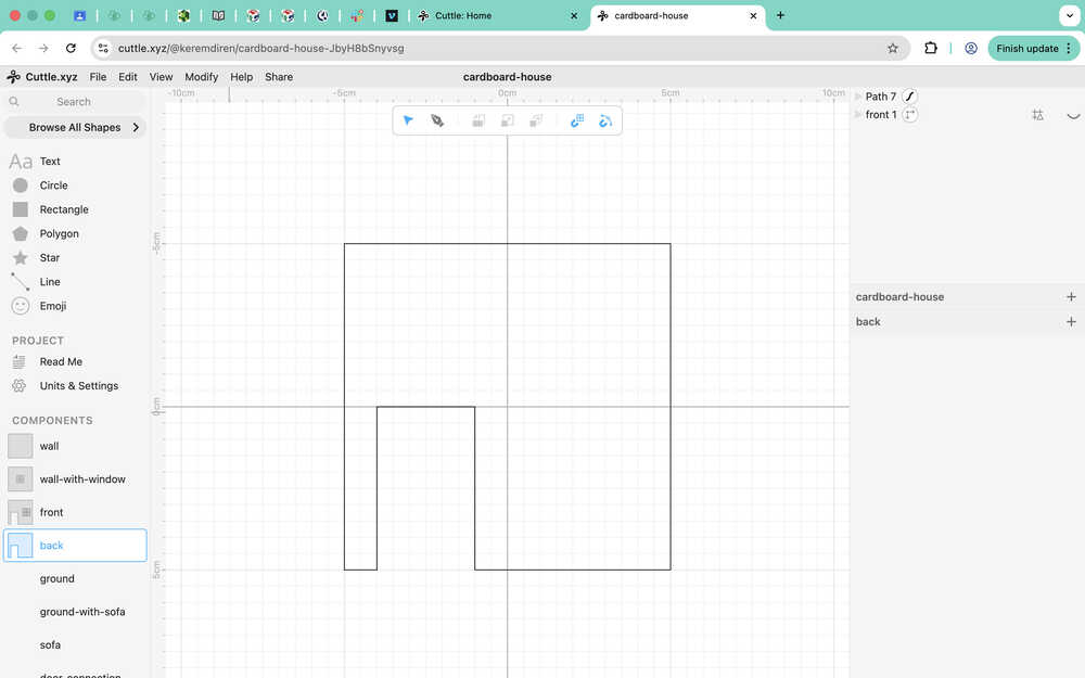
For the back component, I used the front component as a guide.
Since every branch of the wall component is complete, I added a connection part to wall. I used the 180°-connection component as a guide to quickly do this.
I realized that, since I used the pen, the changes I did for the wall component didn't update all of the branches of the wall. That's why I had to redraw some using the pen.
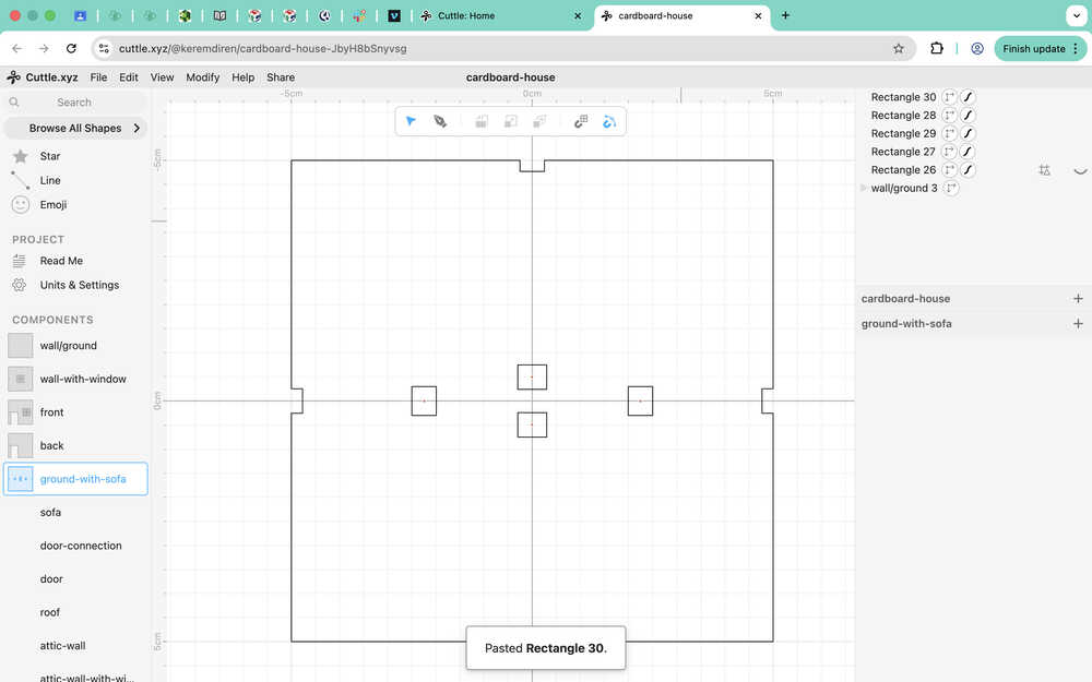
Because the wall and ground components are exactly the same, I just renamed the wall component to "wall/ground" instead of making a ground component.
I created the ground-with-sofa component by using wall/ground and by creating some connection points for the sofa.
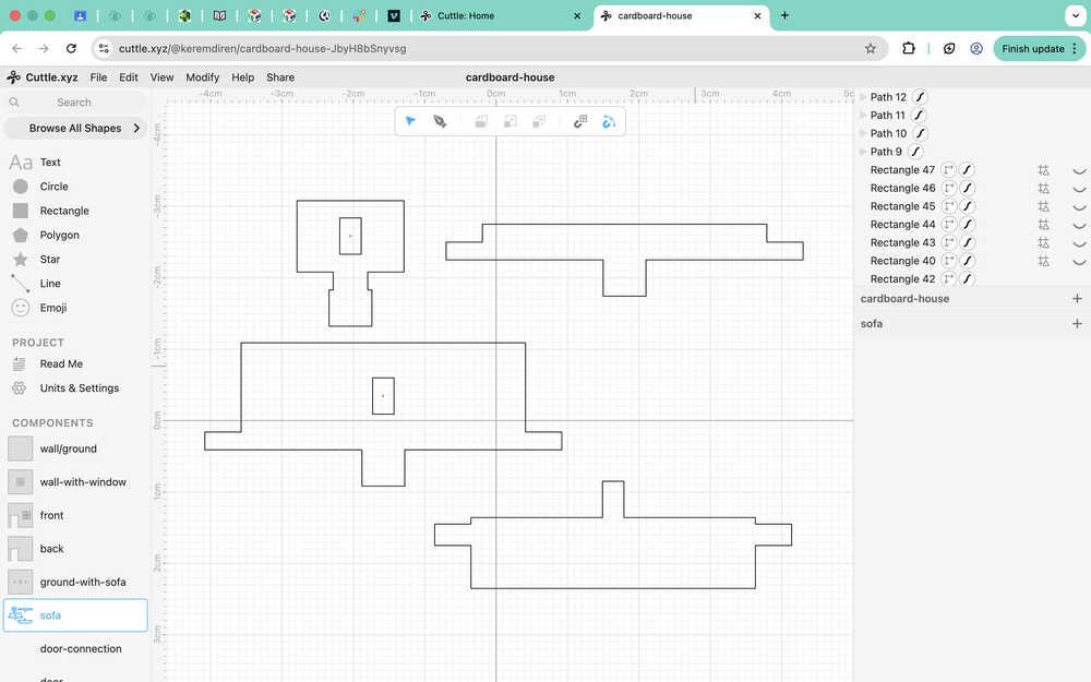
I created some guides for the sofa's parts (the names are temporary; I put them to show which part was which in the documentation).
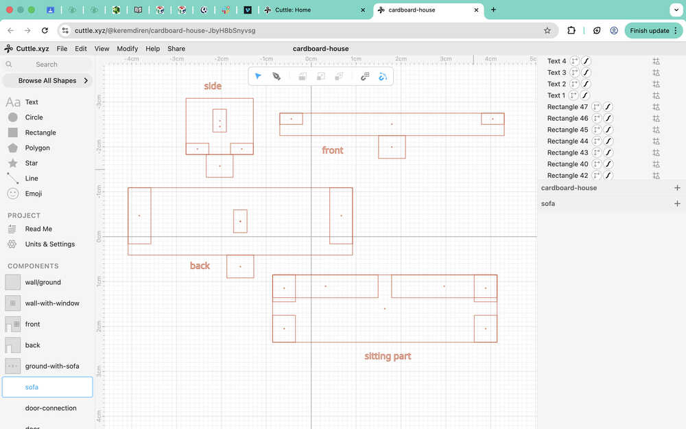
These are the parts of the sofa component.
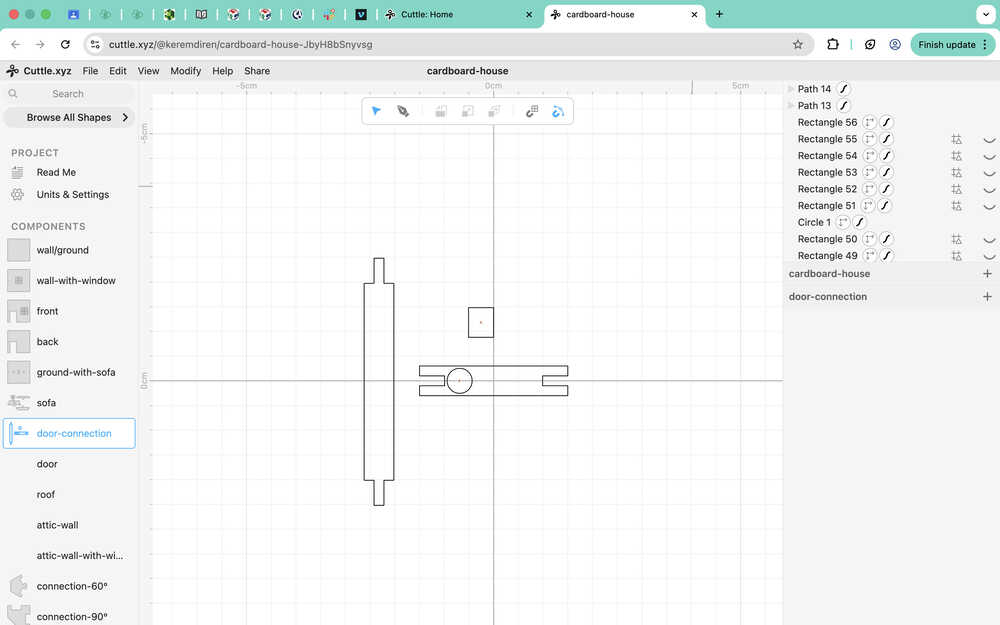
These are the guides for the door-connection, which is basically a door frame. I'll need two of each to make the door openable without damaging it. The small rectangle is basically the thing that'll go inside the circle part. The medium-sized rectangle makes up the top and bottom of the door frame, while the big-sized one makes up the sides of the door frame.
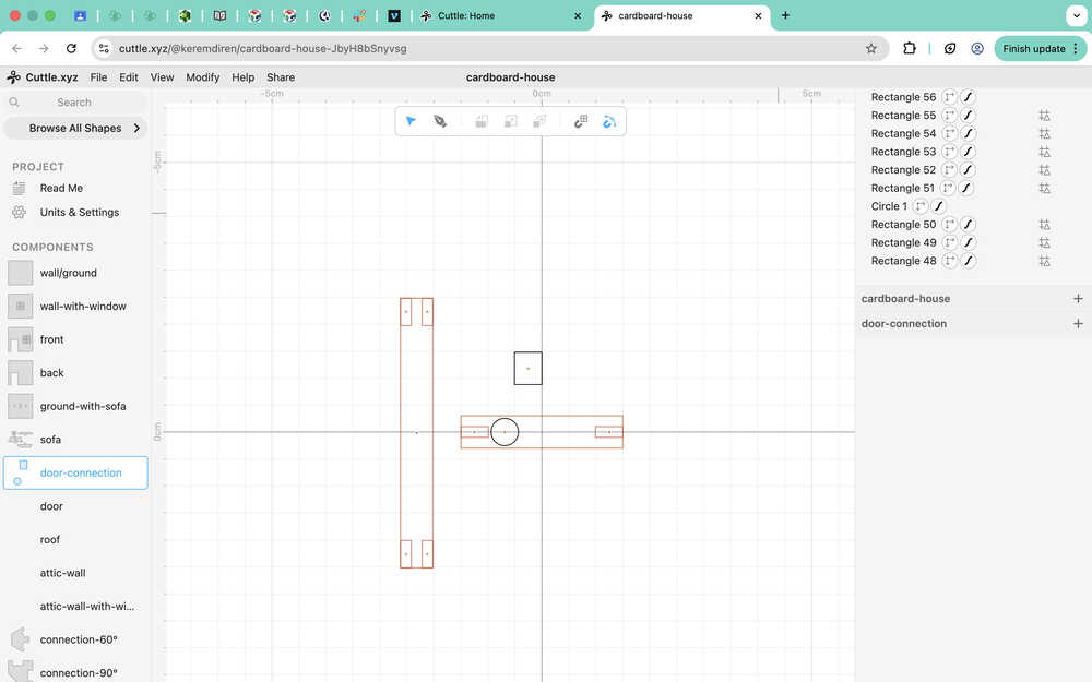
Door connection:
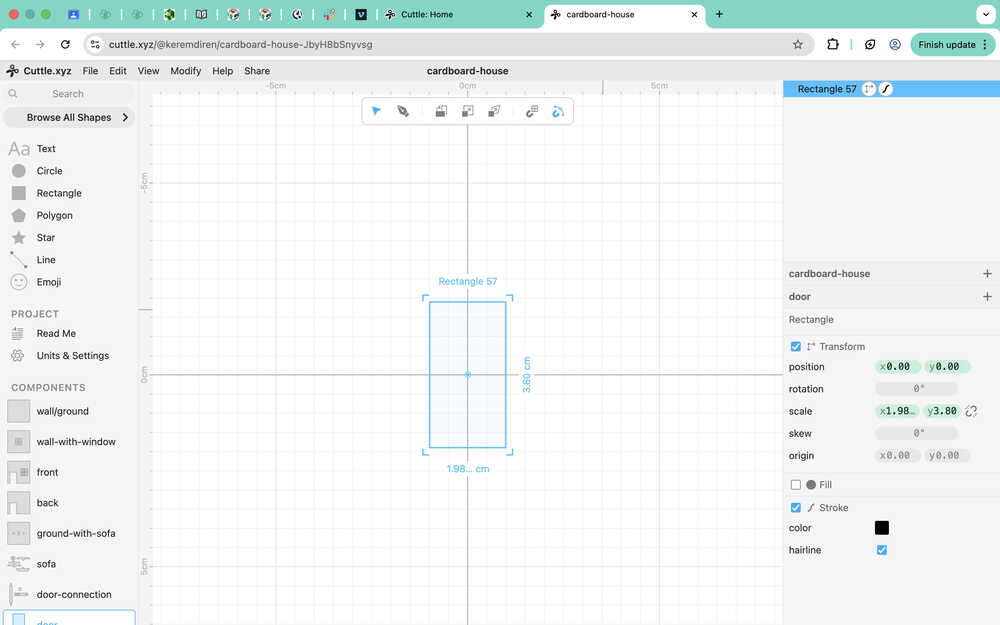
This is the door itself.
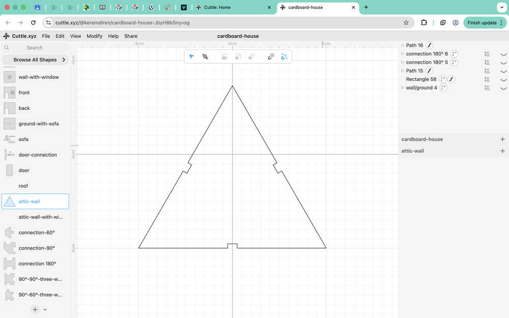
Attic-wall's guide (used wall/ground component for this):
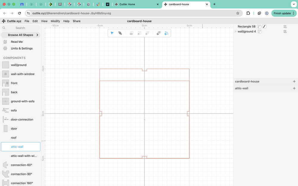
I used √(75) as the height of the attic wall.
Second guide for attic-wall.
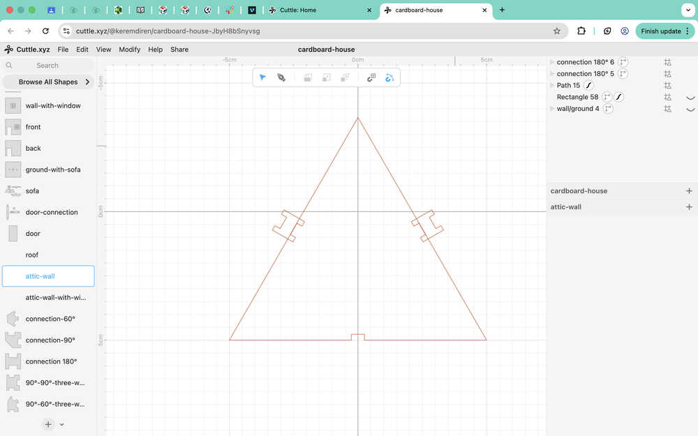
Attic-wall:
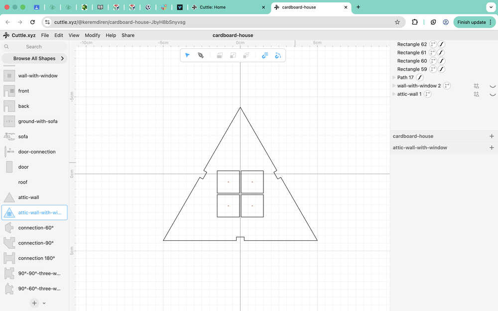
For the attic-wall-with-window component, I used attic-wall and wall-with-window as guides.
I realized that the roof component is the same as the wall/ground component, so I'm deleting the roof component and just renaming the wall/ground component to wall/ground/roof.
Tools Used
Transform
Lets you change the position, size etc. of the element.
Rectangle
Lets you create a rectangle that you can edit.
Pen
You can use the pen to make different shapes and lines. While the pen is equipped, a line will be drawn between the two points you clicked. Using guides and grid/geometry snapping improves pen performance a lot (at least in my case).
Group
This function groups elements so that you can move and change them at once. However, you can still edit them separately.
Guide
A guide is basically like a comment on a code. It doesn't get included when exporting and is only there to help the user.
Grid Snapping
Activating this function makes it so that your cursor automatically targets grid points when moving something.
Geometry Snapping
Activating this function makes it so that your cursor automatically targets specific points (mid-point, corner etc.) of shapes and lines.
Fusion
Design Goal
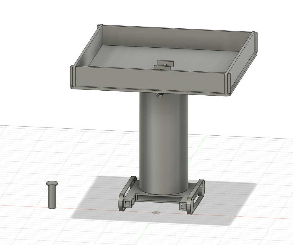
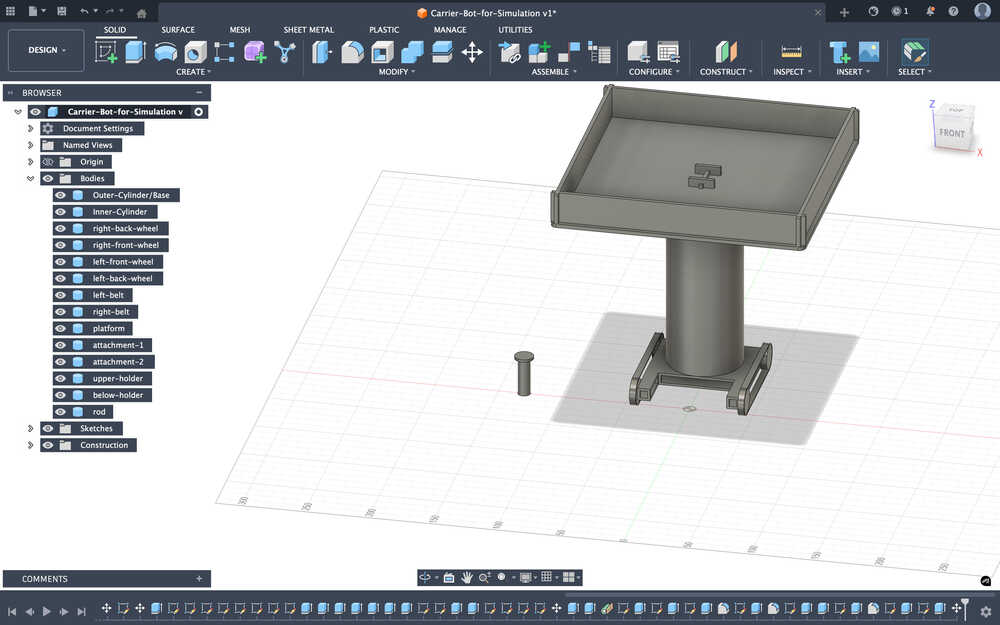
I will be creating my project in 3D for this design. This design will be smaller than how big its final version will be. The platform in this design is the platform I designed in Cuttle; I'm recreating it in 3D because I want to animate this model in Blender.
Final Version
Design Process
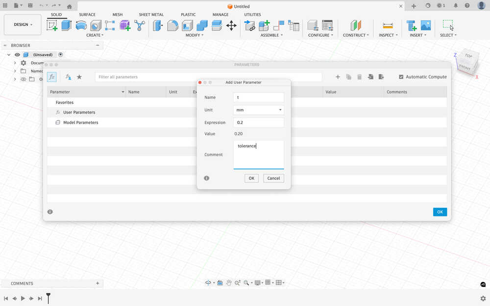
I first set a value for tolerance (0.2mm) from the parameters screen, which can be found in the modify section.
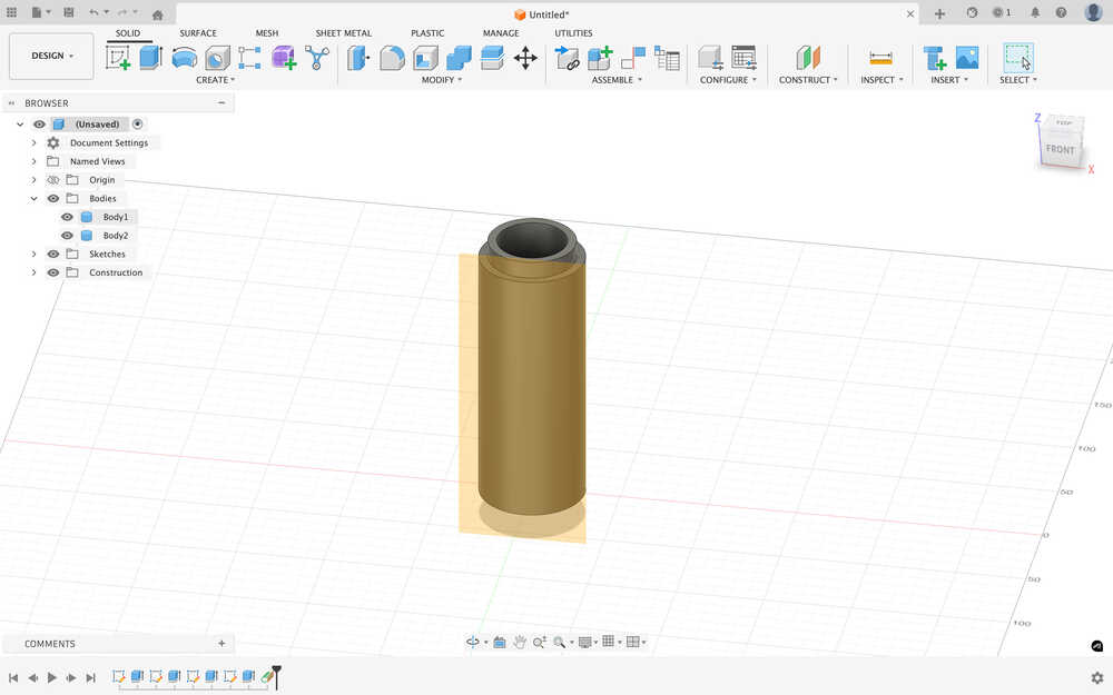
There will be two hollow cylinders, the smaller one will be inside the bigger one. I plan to make the inside diameter of the smaller one about 40mm because that will be where the carrier part of the bot (the one I just designed from Cuttle) will be connected to the middle part of the bot, which needs enough space to connect. I will make the thickness of the cylinders about 0.5cm. That's why the outer shell of the outer cylinder will have a diameter of about 60mm.
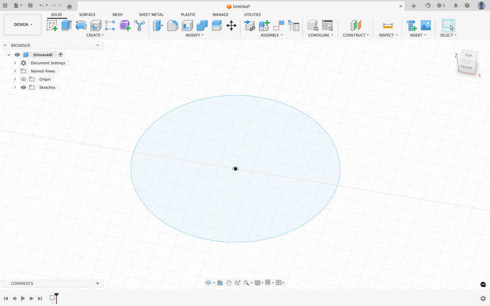
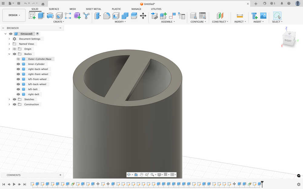
I first sketched a circle with 6cm diameter.
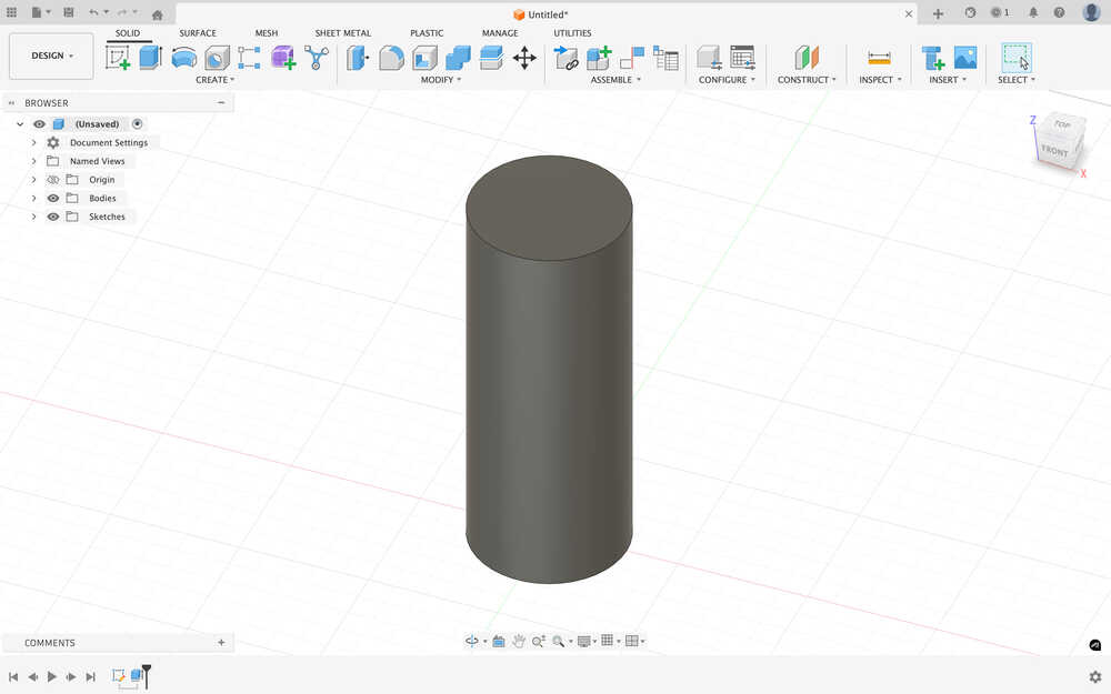
I extruded the cylinder to 150mm.
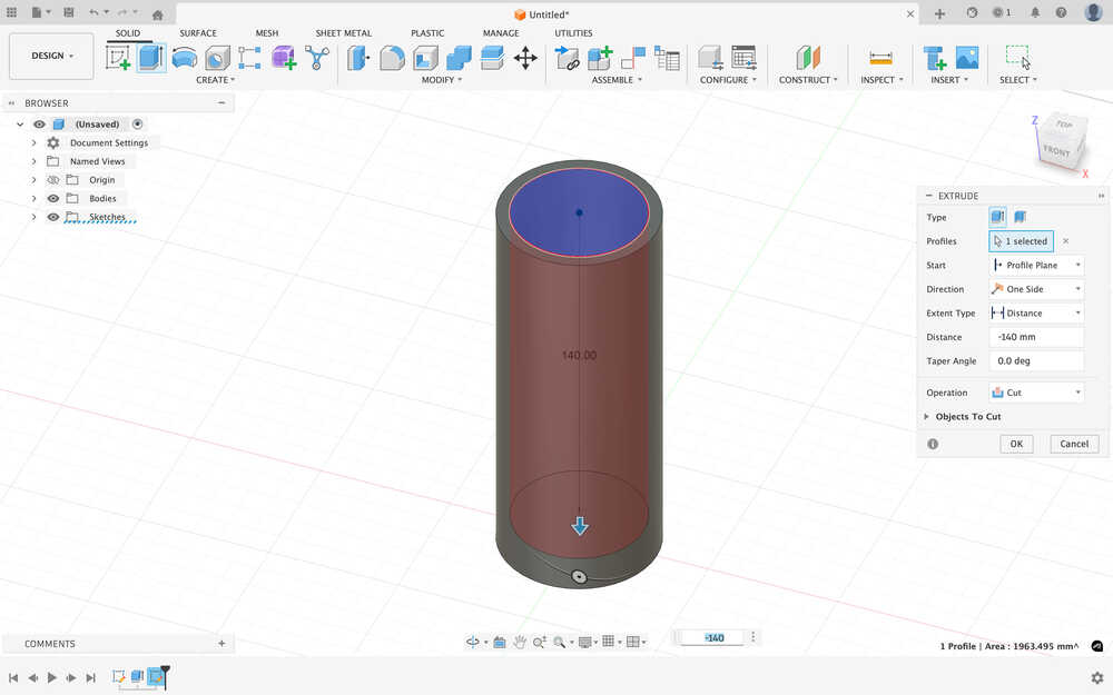
I created a 50mm diameter circle on top of the cylinder. Then, I cut the cylinder by 140mm.
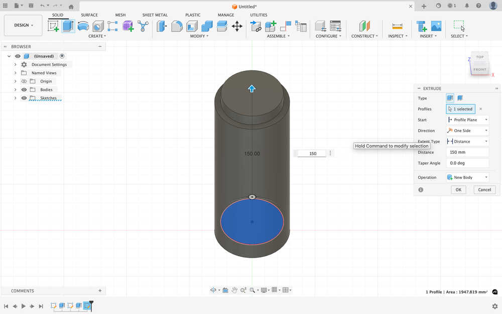
I sketched and extruded another cylinder inside the big cylinder, which's diameter is 50mm - tolerance, which is 49.8mm. I extruded the cylinder to 150mm.
I made a hole in the smaller cylinder with a diameter of 40mm - tolerance, which is 39.8mm.
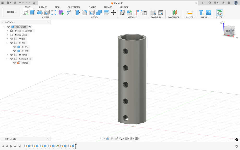
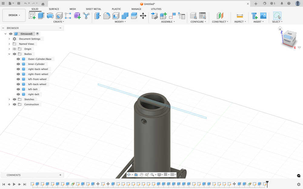
I created a tangent plane on the big cylinder.
Using the plane, I made a hole 10mm diameter in the two cylinders.

I hid the outer cylinder.
I created a bunch of holes on the inner cylinder.
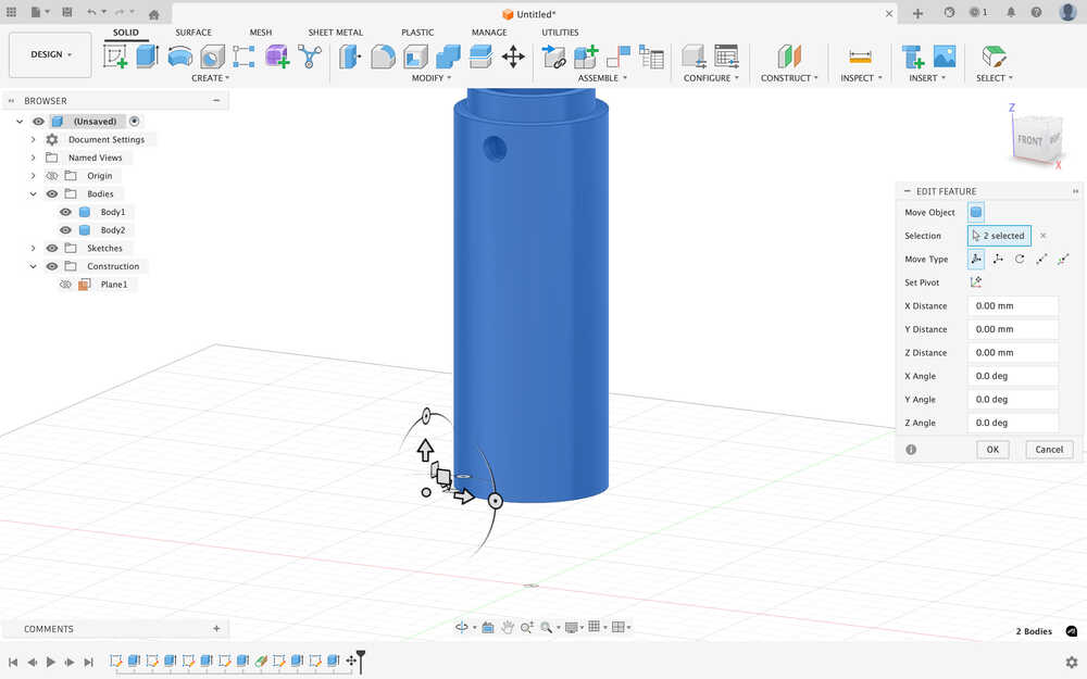
Using move, I moved the bodies 40mm upward.
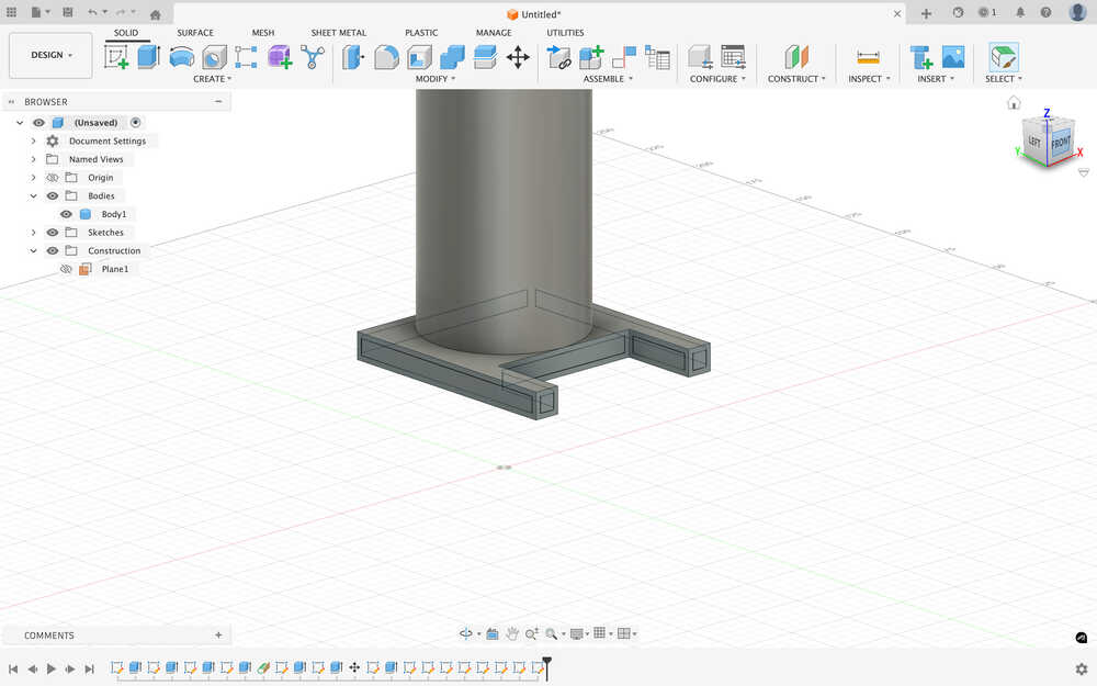
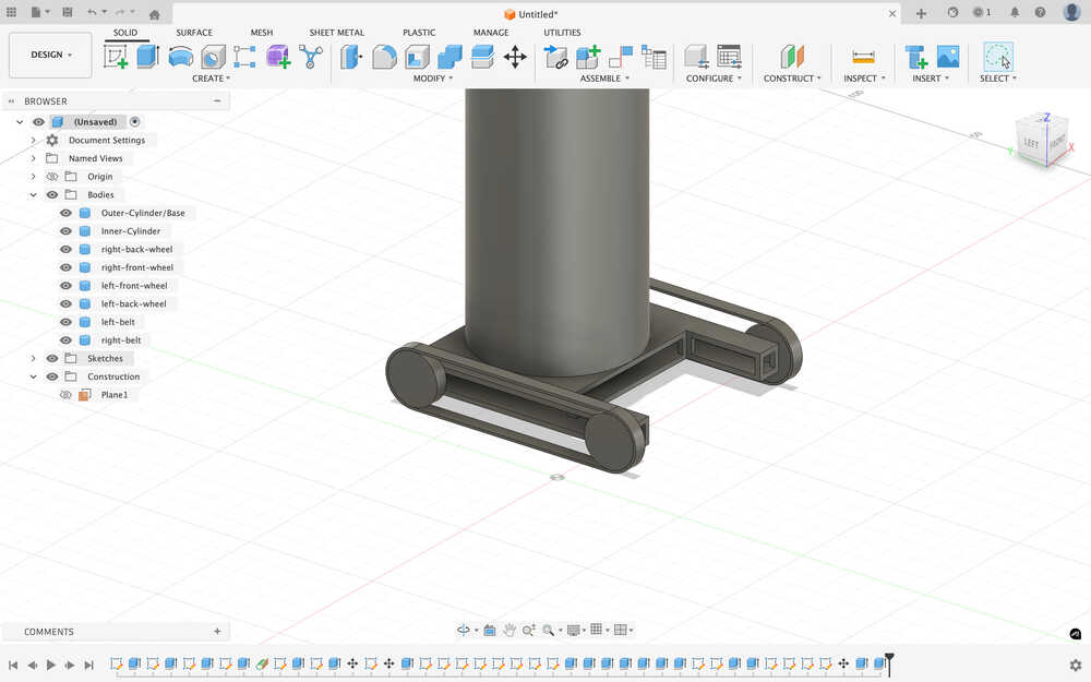
I created an extension to the outer cylinder to have a place to put the wheels at.
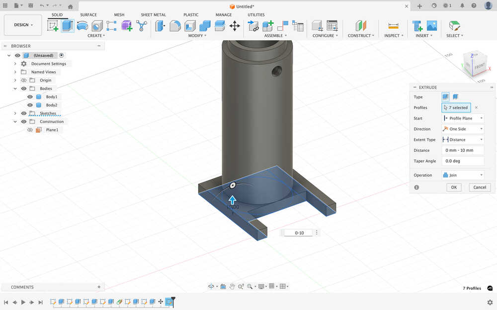
Using offset, I created a bunch of rectangles that are 2mm smaller than the original size of the rectangle.
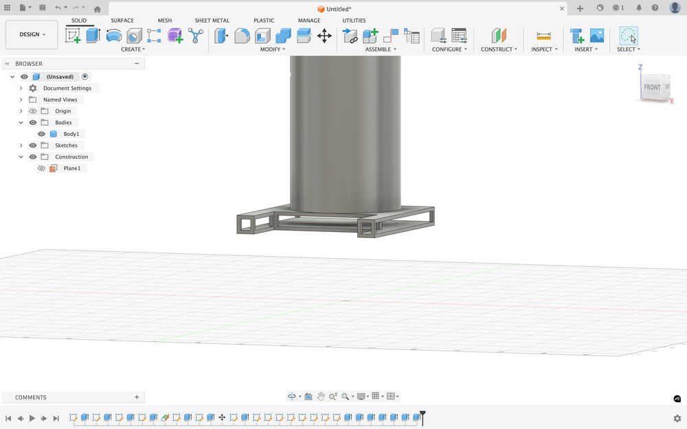
I made the bottom part hollow to make it possible to use cables when the time comes for me to create the project in real life.
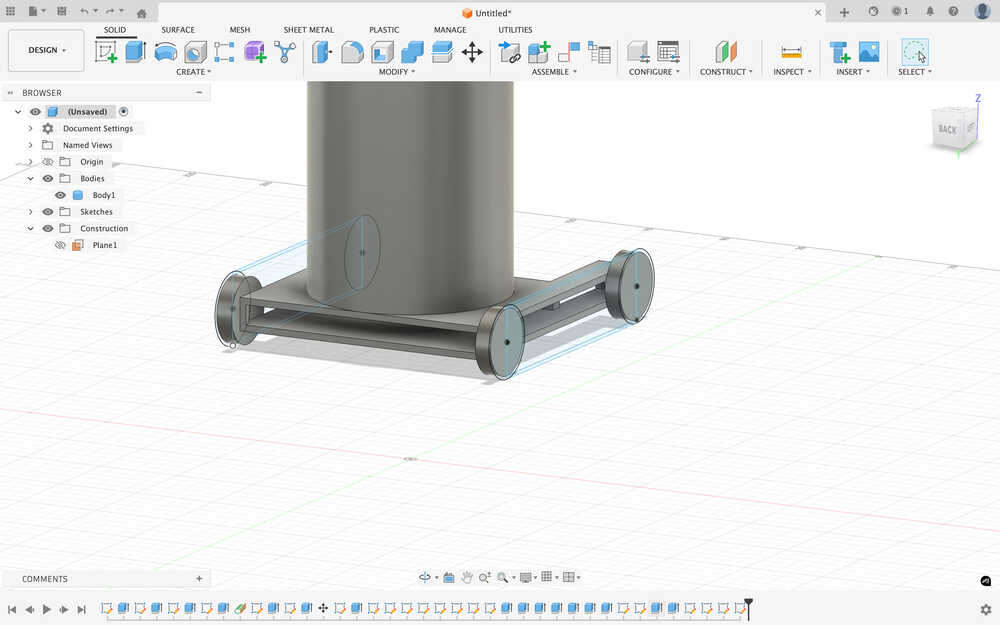
I made wheels with 20mm diameter and 5mm thickness.
I sketched sketches to create belts.
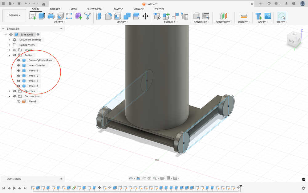
I turned the wheels to four different bodies and named the bodies.
Extruded the belts.
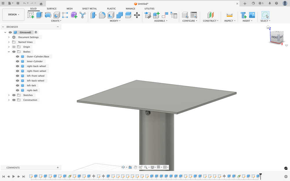
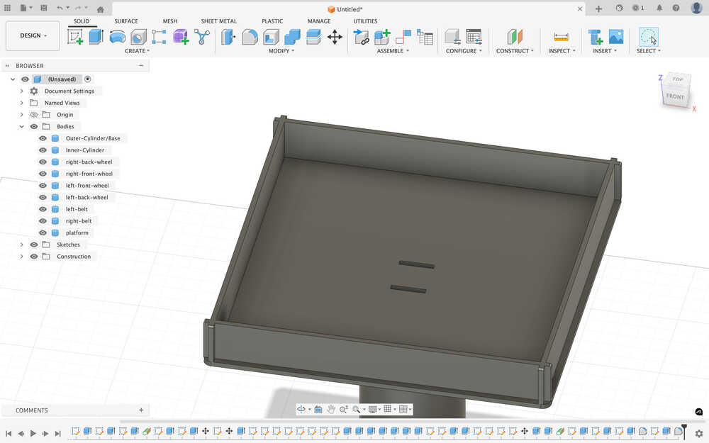
Created a platform on the inner cylinder that'll hold the carrier platform.
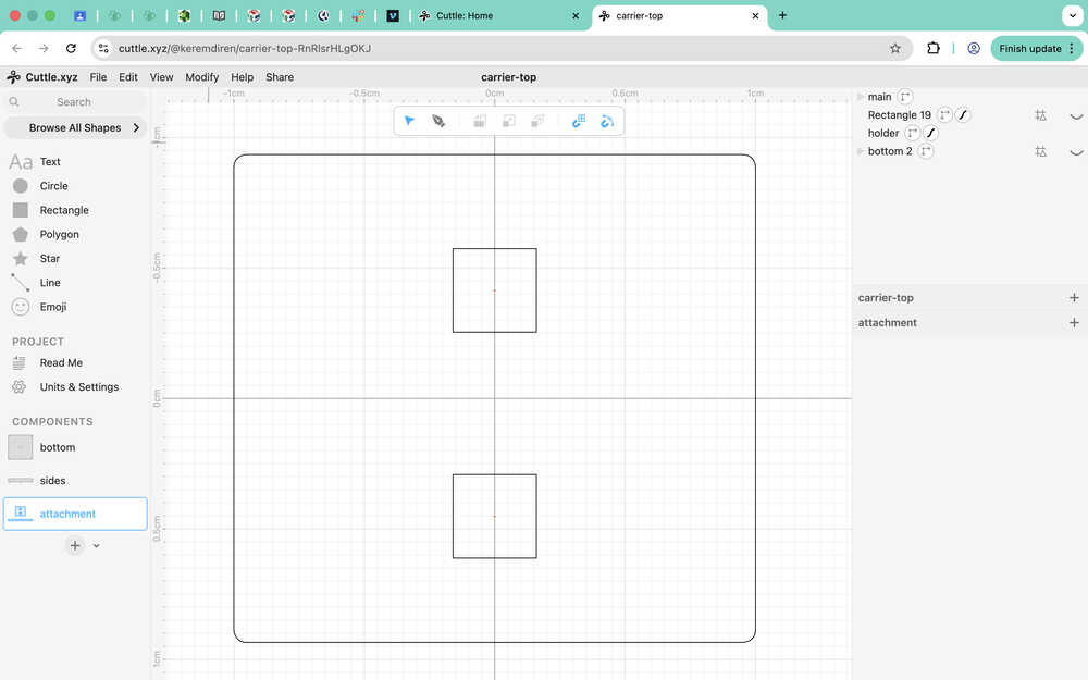
While doing this, I realized that I made the distance between the holes too short in my cuttle platform design. I increased the distance by 1mm. Here is the new version of the attachment component:
I sketched the platform. Its 20cm by 20cm instead of 40cm by 40cm since this 3D design is a smaller version of the real one.
I extruded the platform.
I created the holes for the attachment component (they're smaller than what I designed in Cuttle).
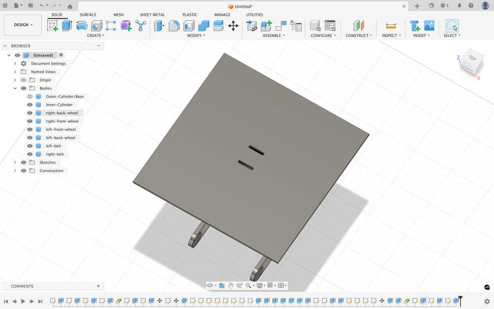
I used fillet to make the edges of the platform softer.
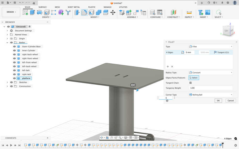
I created the sides of the platform (shorter than what I designed in Cuttle).
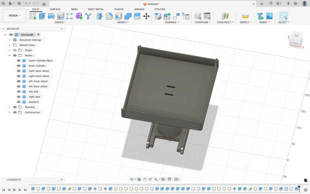
Using fillet, I softened the edges of the edges of the platform.
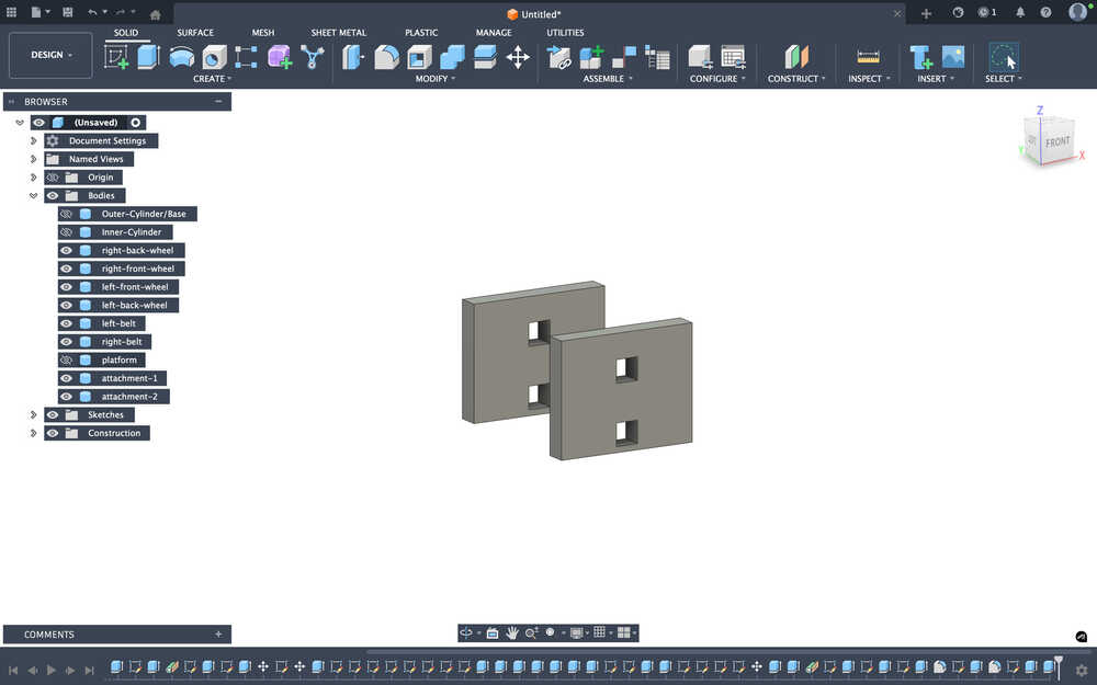
Created the main attachment part.
I created the holder rods and added fillet to the main attachment part.
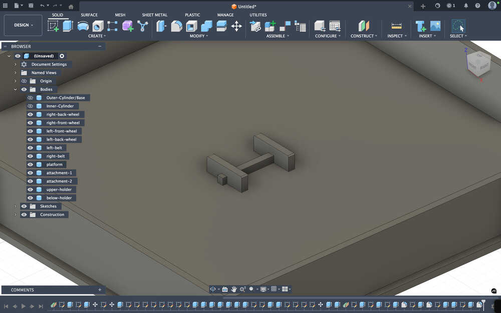
I created a rod that can hold the platform so that its length can be increased.
Tools Used
Sketch
Sketch lets you create something similar to a blueprint for your project. You can sketch shapes, lines etc. There are also tools like offset that lets you sketch depending on a previous sketch (offset basically lets you create a (kind of) scaled version of the sketch you selected). You can use the sketches as a guide for other sketches or for something to extrude (to create objects, delete parts of objects etc.). When creating the sketches, you can also set the values by entering them to the corresponding box in the panel that opens after starting to sketching.
Extrude
Extrude lets you make use of your sketches. There are settings named new body, new component, cut, join, and intersect that let you make use of your sketch in different ways:
- New body lets you create a new body.
- New component lets you create a new component.
- Cut lets you remove the parts of the objects that are touching it.
- Join basically joins the objects you select.
- Intersect takes the intersection of the objects you created and deletes the rest.
There are also settings like profile plane and offset that let you choose from where you want to extrude your sketch.
- Profile plane makes it so that you just extrude from the sketch's location.
- Offset makes it so that you can start extruding a distance above or below your sketch.
Tangent Plane
This lets you create a plane on the selected side of a circular surface, which lets you sketch on that there.
Move
This lets you move the selected bodies.
Fillet
This lets you soften the selected edges depending on the value you enter.
Onshape
Design Goal
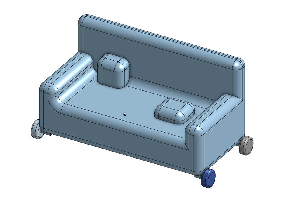
I want to make a sofa with wheels for this project.
Final Version
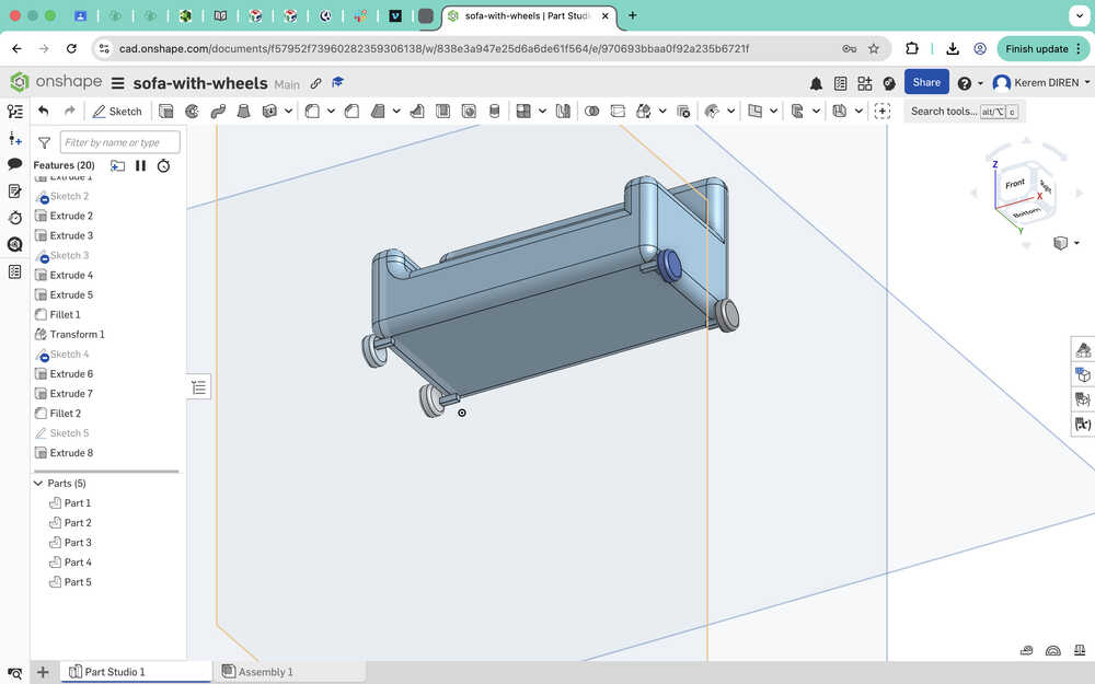
Design Process
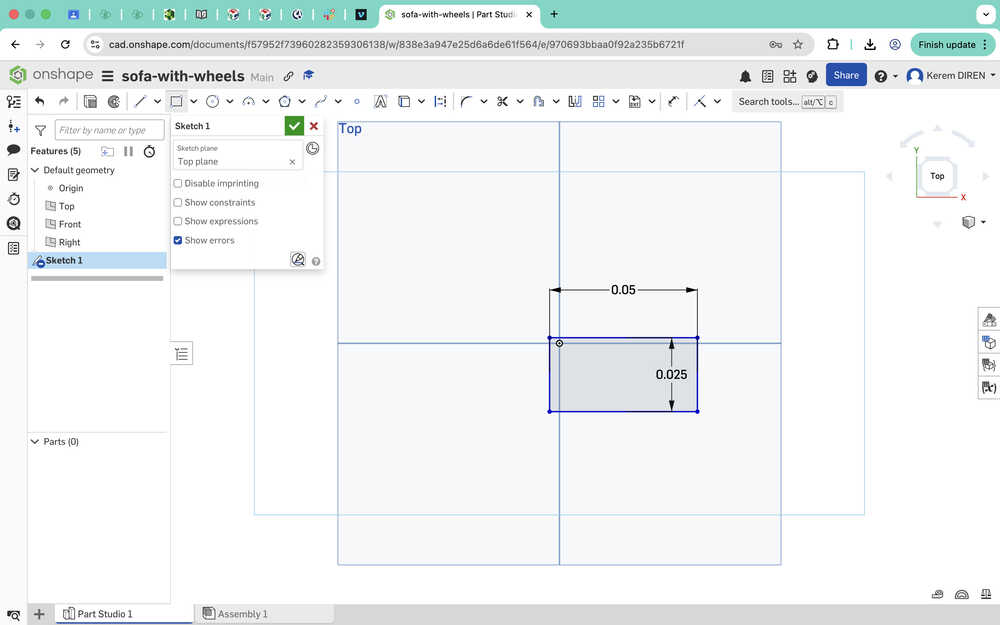
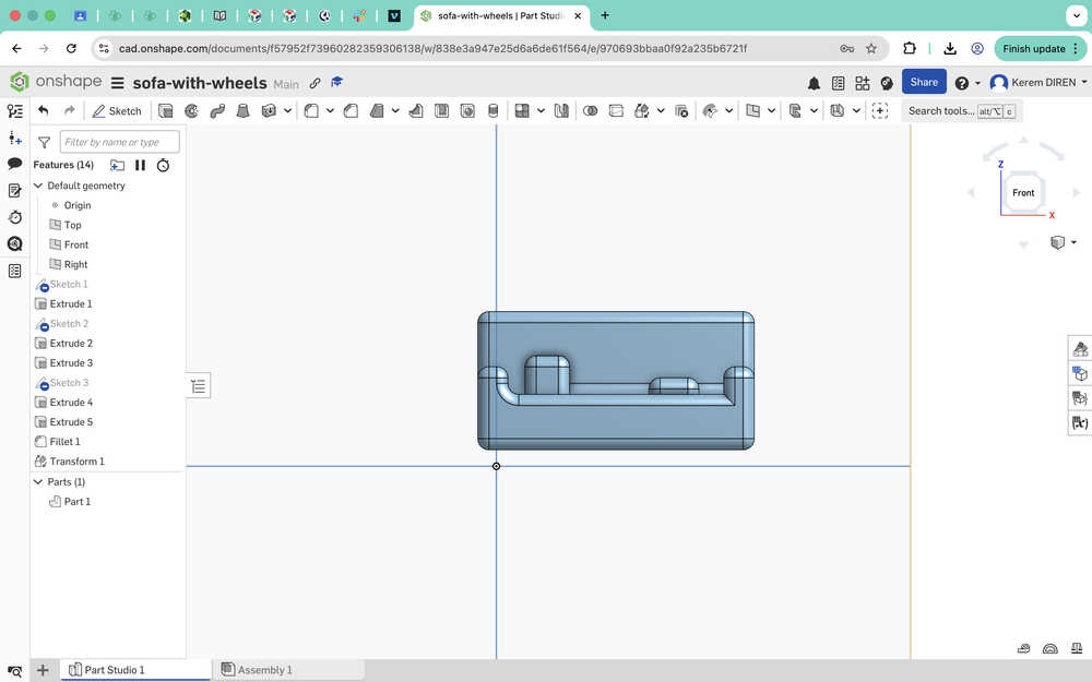
I started with sketching a rectangle with dimensions 25mm to 50mm.
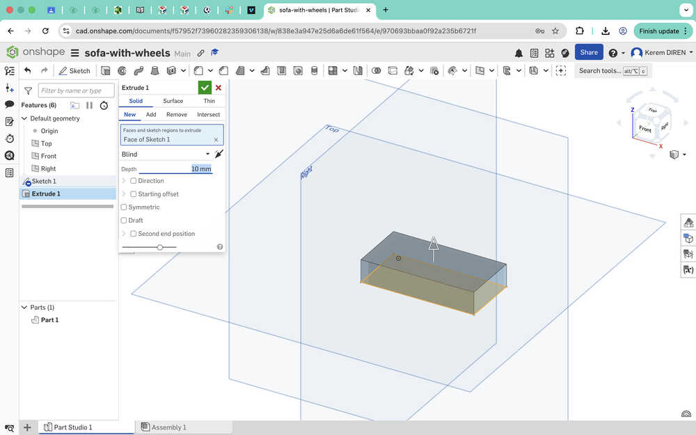
I extruded the shape by 10mm.
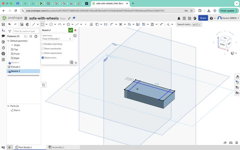
I sketched the sides and the back of the sofa.
I extruded the sides by 5mm.
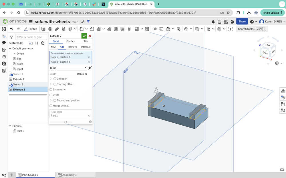
I extruded the back by 15mm.
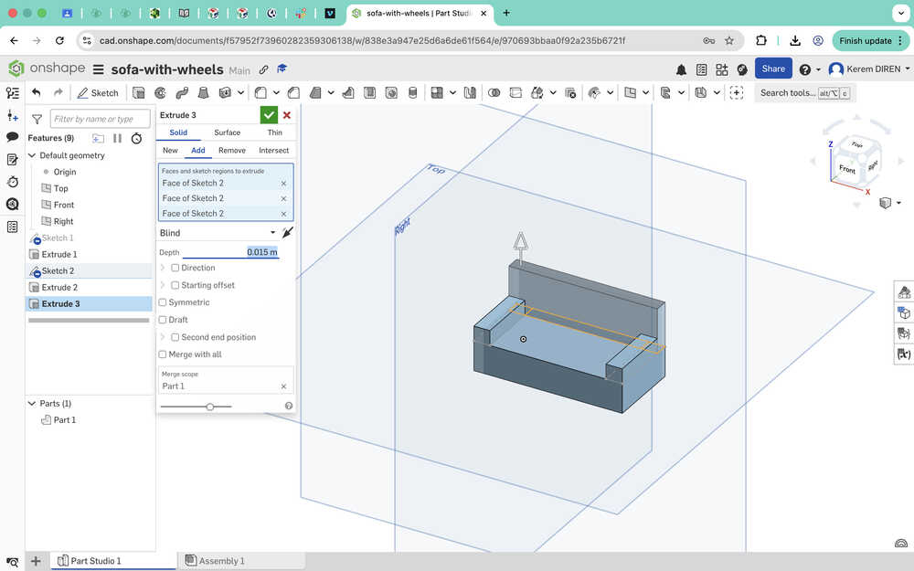
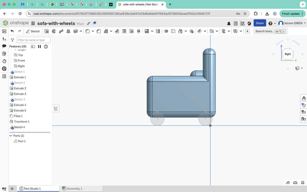
I sketched and extruded two pillows.
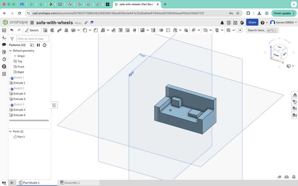
I used fillet to give the sofa a softer look.
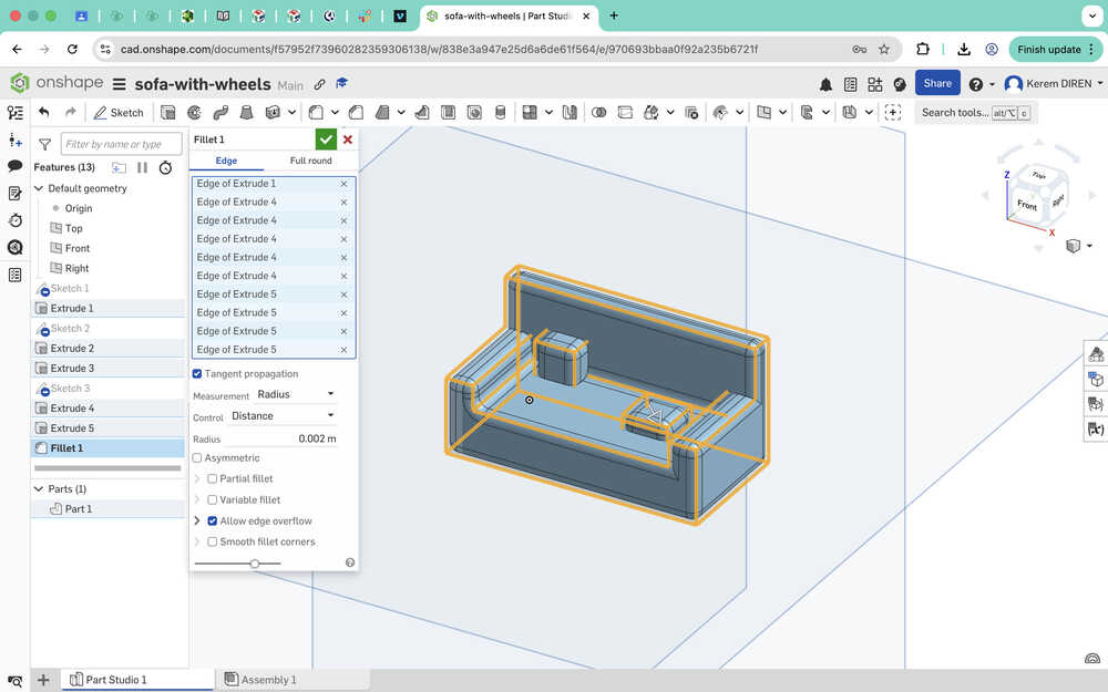
I used translate to increase the sofa's height by 3mm to give it some space for creating the wheels.
I created wheel sketches with a diameter of 5mm.
I extruded them by 2mm.
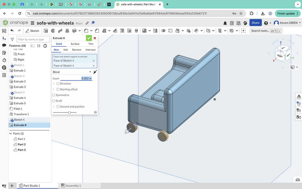
I used fillet on the wheels.
I opened an assembly and exported the sofa to there.
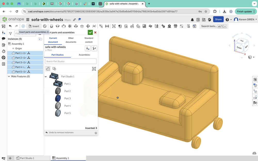
I sketched and extruded parts that'll help me with creating mates.
I made the wheels and the sofa revolution mates.
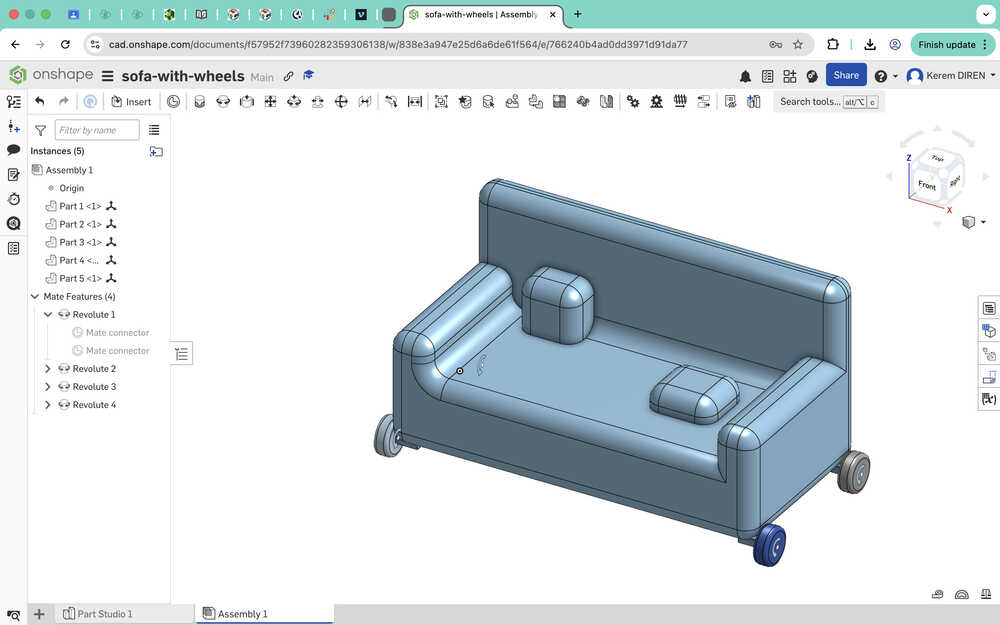
The wheels can turn now
Tools Used
Sketch
Sketch lets you create something similar to a blueprint for your project. You can sketch a shape, line, text etc. to either serve as a guide or to extrude to make something or delete a part of something you created before. Tools like center point circle and corner rectangle helps with the creation of shapes. You can also create points to serve as guides.
Extrude
Extrude is a tool that lets you do something with the sketches you create. It has four settings: new, add, remove, and intersect.
- New lets you create a new object.
- Add lets you add the newly created sketch onto an object you created before.
- Remove lets you create a hole in other objects you created.
- Intersect takes the intersection of two sketches you created, which makes the object you create become the same shape as the intersection of the two sketches.
Translate
This tool lets you change the position and the angle of the object you selected.
This tool lets you soften the edges you selected.
Mates are kind of similar to joints in Fusion 360. It lets you create a relationship between two objects: one is stationary and the other can move. You can click the "animate mate degree of freedom" button to see the relationship between the two mates. You can also set limits to make the animation seem more realistic.
Blender
Design Goal
I will animate my 3D final project model. After a button is pressed, the bot will start to speed up from 0 velocity, go at constant speed, then slow down to 0 velocity.
Final Version
Design Process
I first exported my project as an stl type file.
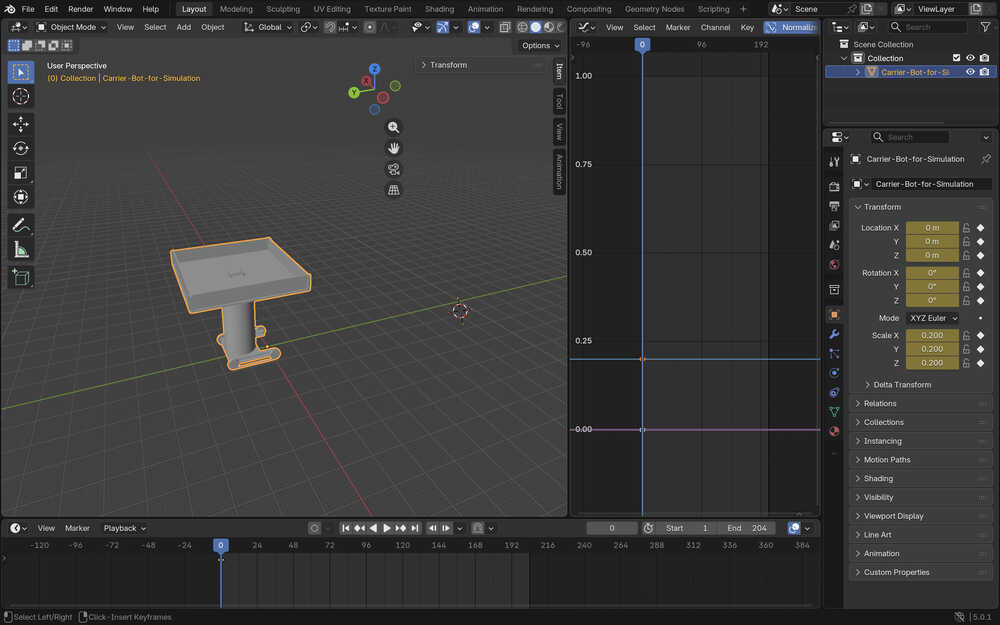
I imported the file into Blender.
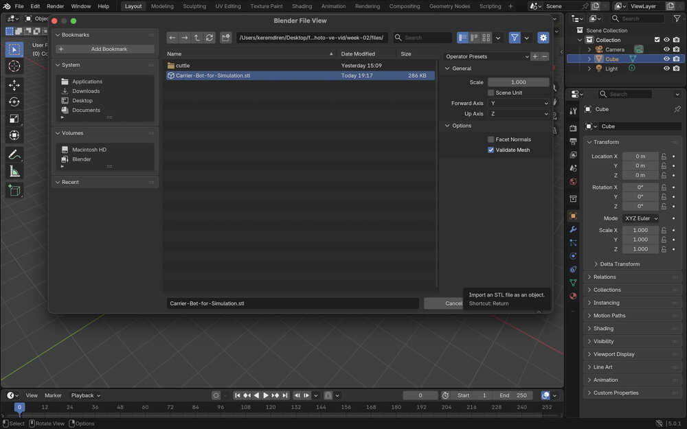
I also deleted the cube, camera, and light elements.
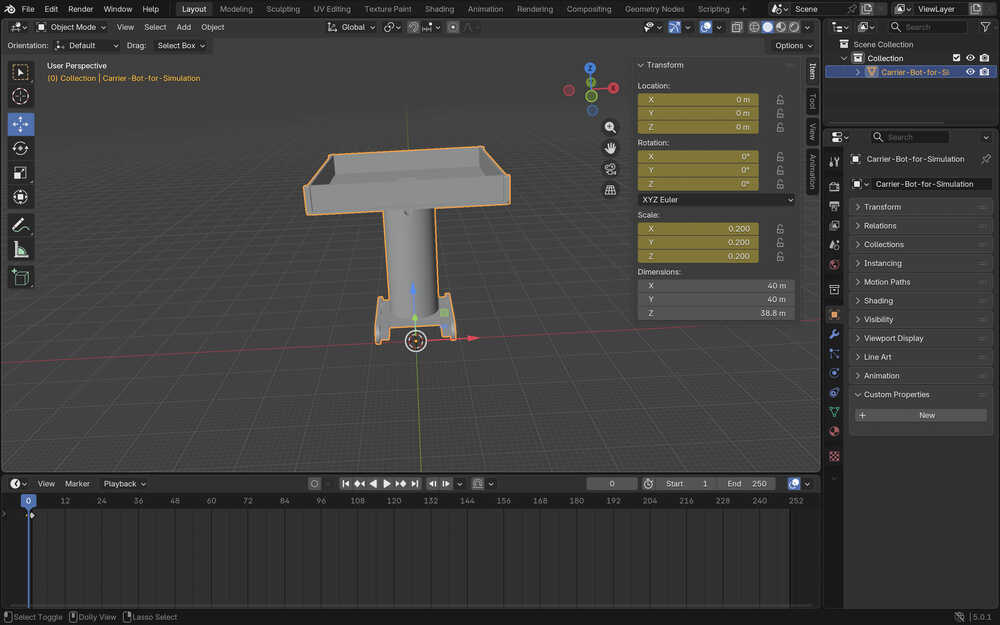
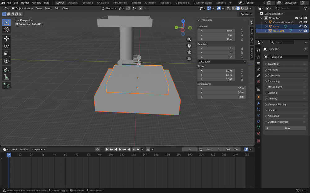
I opened the layout screen and scaled the object to be one fifth of its size before.
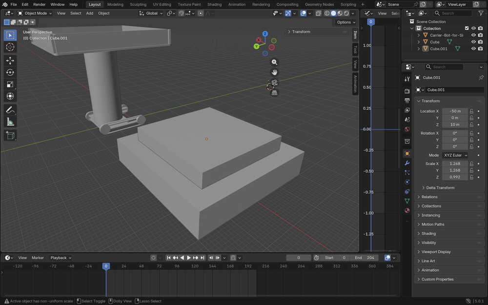
I created two cubes. They will act as a button. Their dimensions are 40x40x8 and 30x30x5.
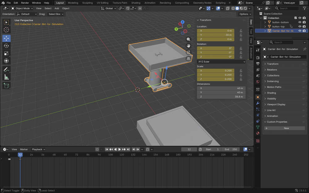
I created another keyframe at frame 12, which is when the bot is at position Y = -30.
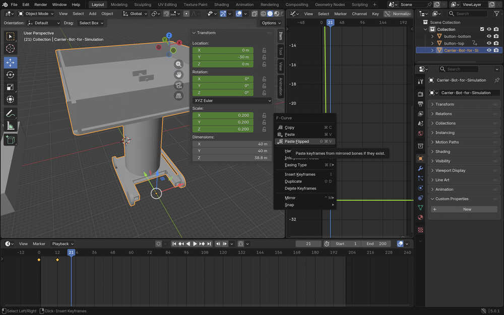
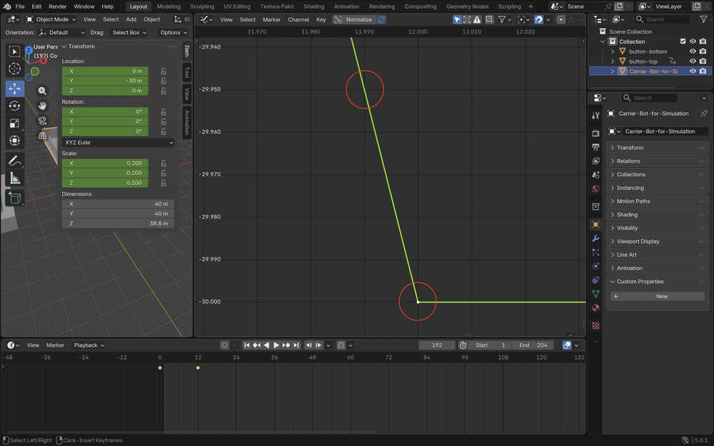
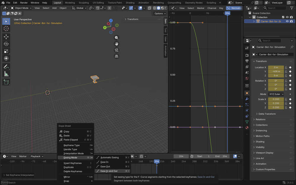
I made the bot look like it's speeding up using the graph editor, right clicking on the keyframe, and selecting an option that looks like the one in the photo.
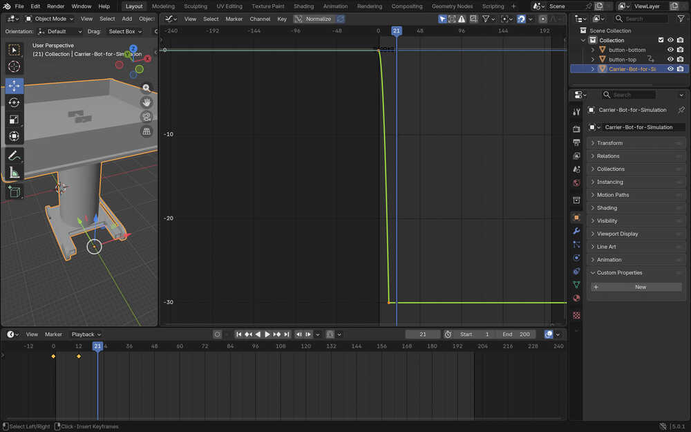
I zoomed in a lot, took two points, and determined the velocity after the speed up to be about -5m/s.
With the equation (192 - 12) / 24 * (-5) + (-30), I calculated the final position (after constant velocity) to be -67.5. The equation is (last_frame_of_constant_speed - first_frame_of_constant_speed) / frames_per_second * speed + starting_position_of_constant_speed.
The position didn't seem right, so I was going to recalculate it; however, because I zoomed in too much to the graph, Blender crashed, and I had to do everything again from the start.
Apparently, the graph becomes more horizontal around the end, which is why I calculated the speed wrong.
I played with the two sticking out from the end of the keypoint. After that, I decided to take the slope from somewhere a little above the last part.
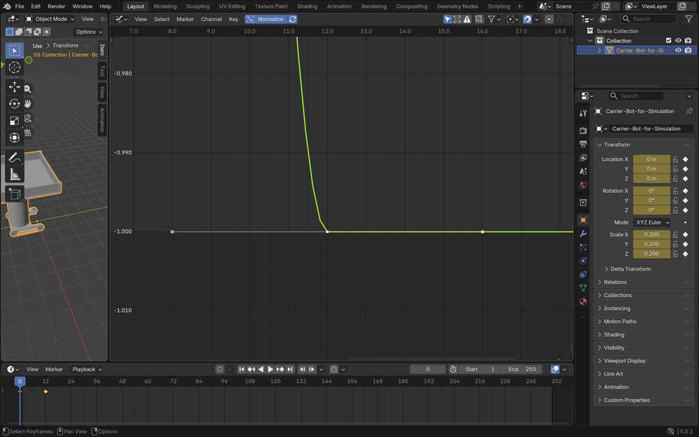
I changed the slope at the end a little bit more. I took two points again. According to my calculations, the slope is now about -60. This means that the position after the constant velocity part is now -480.
I created a keyframe at the position -480 and frame 192. The animation, however, didn't look that good. So I decided to do this using another technique.
I, once again, created a keyframe at frame 0 and at position 0.
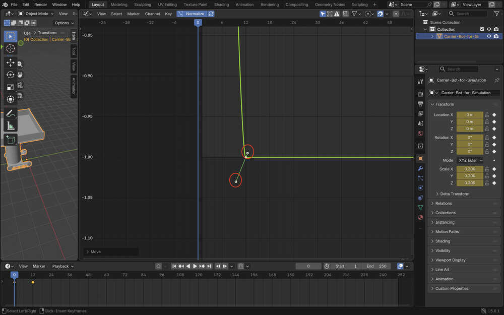
Then, I created a keyframe at frame 204 and position -408.
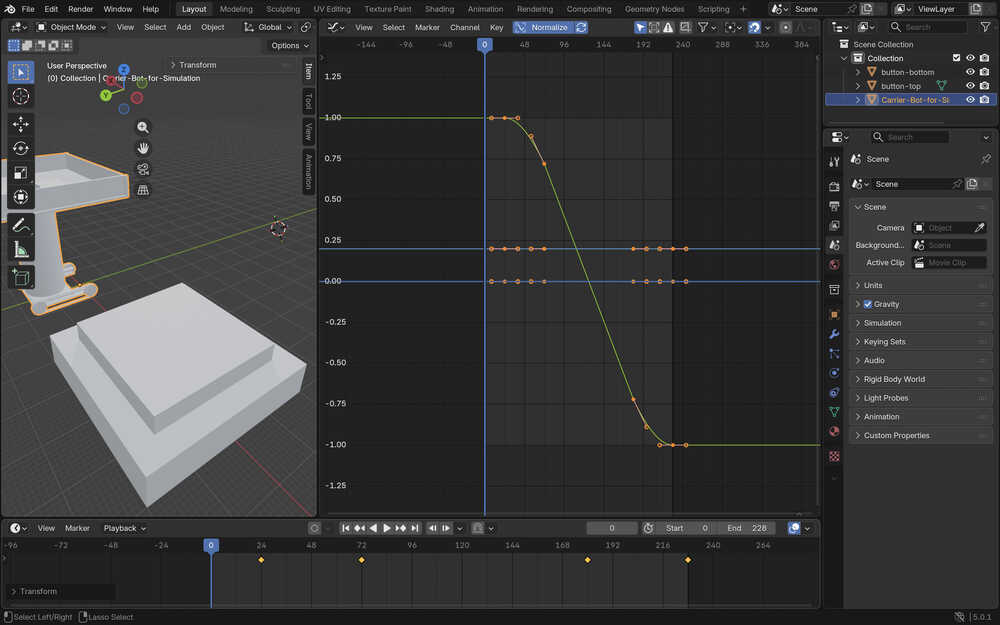
I selected the two keyframes and selected an easing mode named "Ease in and Out".
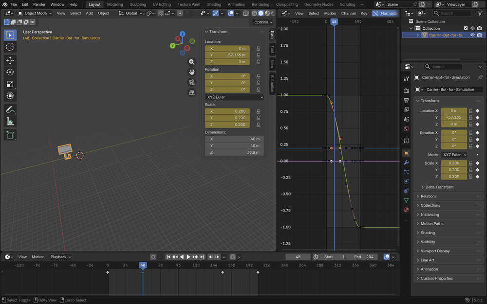
I went to frame 48 and noted the position at that frame, which was -57.135m. I also went to frame 156, which had the position -350.865m. I put keyframes to these frames at these positions.
Finally, I selected the two keyframes I last created and changed their interplotation mode to linear.
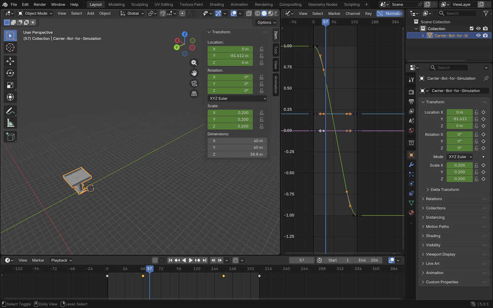
This made a nice speeding up - constant speed - slowing down animation.
Now, its time to recreate the button. I used two big boxes, just as before.
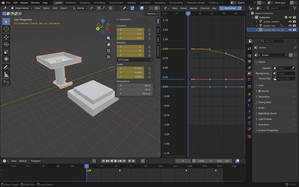
I set the end frame to 228 and changed the position of the keyframes of the bot 24 frames further than zero. I did this because I wanted to leave some space for the animation ofdthe button being pressed.
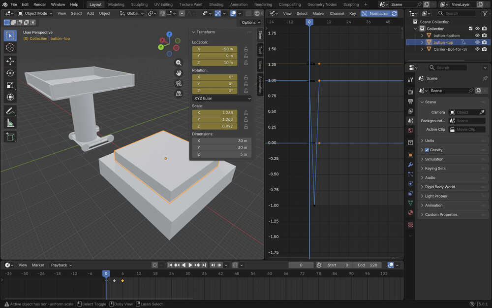
I created a keyframe for the button-top element to make it start at the correct position. I also created two more key frames so that it is fully pressed at frame 12 and then fully retracted at frame 24.

I changed the interplotation mode of the button to linear.
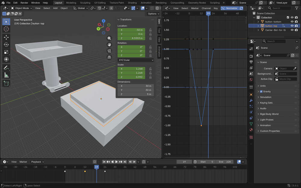
Because I didn't like the speed of the button being pressed, I decreased it to the quarter of what it was before
I also changed the start of the bot's acceleration to the 6th frame since that is the exact frame the button is fully pressed.
Tools Used
Add Cube
You can add a cube. Hold mouse button 1 to set the x and y dimensions of the cube by dragging your mouse (hold shift to make it a square). Then, stop holding, set the z dimension by dragging you mouse, (or hold shift to make it a cube) and click to finish creating the cube.
Keyframes
Select a frame, change the values of the element to be how you want it to look like when it is at that frame, then press i to create the keyframe.
Scale
Scale the object's x, y, and/or z dimensions.
Move
Move the object in the x, y, and/or z axes.
Delete
Delete an element by pressing x.
Graph Editor
This lets you modify elements' transition from one keyframe to another.
Compressing Image and Video Files
Compressing Images
I first downloaded Image Magick from here.
I navigated to the file with my photos using the cd command in my terminal.
I first used the magick mogrify -format jpg .png command to turn my images into jpg format.
Then, I used magick mogrify -resize 1000x\> -quality 50 .jpg to decrease their size (if they're too big) and quality.
Compressing Videos
I first imported the screen video I took into iMovie.
Then, after editing it however I want or after not editing it at all, I named it and howevered my mouse on the project.
I clicked to the three dots that just appeared and chose "share".
Then, I selected "file", set the settings of the file to a minimum, and exported it into my desktop.
Files
You can download the files by clicking here.