Here are my project ideas and final project documentation.
You can reach to my past and current projects through my GitHub at the About Me page. Also, the projects that me and my group do as an assignment will be posted and documented through here.
First Idea: The Smart Health Assistant Coaster
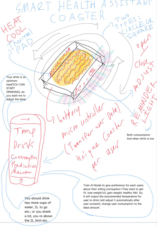
I wanted to design a piece of technology that could genuinely help people achieve their health goals, moving beyond simple fitness trackers. That’s why I created the concept for the Smart Health Assistant Coaster.
The core idea is simple: a smart coaster that monitors your fluid intake, optimizes your drink temperature, and uses AI model to give you highly personalized health advice based on what you’re drinking.
The Hardware: The Smart Coaster
The coaster itself is the physical interface. I designed it to be available in both square and circle shapes to fit different mugs. It needs to be practical, so it has an Open/Close mechanism.
The key feature is the dynamic temperature control. Using a Heat/Cool Thermal Pad, the coaster can keep any drink at its ideal temperature. If my coffee is getting cold, it heats it up. If my iced tea is warming, it cools it down (I am thinking about using a specific material for the smart coaster to help cool the mug/glass over it to cool up, or I might just get rid of this idea, and just pursue into a idea that it just reminders the user via the app when their drink became the temperature they want). The coaster houses a battery and a microcontroller to manage all this. This microcontroller is crucial because it tracks consumption and transfers all that data to my app. I envision making this a unique coaster per user so the system is entirely personalized.
The coaster also has a visual reminder—a Reminder Light. This light tells me two things: whether I’m actively consuming the drink, and when the drink is running low. I also included a simple Adjust function to quickly change the set temperature.
The Software: The Mobile Health App
The mobile app is the brain and the dashboard. It shows me the real-time status of my drink.
Crucially, it handles the two-way communication:
Temperature Alert: It can give me prompts like, “Your drink is on optimum heat (YOU CAN START DRINKING), do you want me to adjust the temp?”
Consumption Tracking: It records my Consumption and uses a Predictive Recommender(for a specific diet that the user wants) to give me advice.
The Intelligence: The AI Model
This is where the “Health Assistant” part truly shines. I plan to train an AI Model specifically to personalize my health goals. I will input what I want to achieve—whether that’s to get fit, lose weight, or just maintain a healthy life.
Based on my goal and my current consumption habits, the AI will:
Adjust the Ideal: Automatically adjust the recommended temperature for my drink and tweak the ideal daily consumption amount.
Give Direct Advice: The app will then tell me exactly what I need to do to meet my goal, delivering highly specific alerts like, “You should drink two more cups of water, 2L to go, etc.; or you drank a lot, you’re above the 2L limit etc.”
Ultimately, the Smart Health Assistant Coaster is a holistic system that ensures my hydration is optimized for both enjoyment and health, acting as a constant, intelligent coach right on my desk.
My Final Project Idea: The Commercial Smart Coaster
After developing my initial idea of a Smart Health Assistant Coaster, I decided to pivot into a more commercial and entrepreneurial direction.
Instead of focusing only on personal health tracking, I redesigned the concept into a Commercial Smart Coaster System that can be used in restaurants, cafes, and chains.
The main idea is simple:
A smart coaster with a display, LED, buzzer, and button system that can receive messages and show advertisements while also acting as an interactive notification device.
This allows businesses to:
Display advertisements directly on tables
Create a new revenue stream through ad partnerships
Improve customer interaction and service signaling
At the same time, the system remains simple, scalable, and practical for real-world use
The Hardware: Commercial Smart Coaster
The coaster is the physical interface between the system and the user (customer).
I redesigned the coaster to be:
Circular (better aesthetic for restaurants)
Compact and durable
Capable of housing electronics cleanly
Inside the coaster, I use a microcontroller-based system that controls all inputs and outputs.
The coaster includes:
Core Features
- Display Screen (OLED)
Shows advertisements, messages, or status info
Can later be upgraded to a round TFT display
- LED Indicator
Provides quick visual alerts
Example: blinking when a message arrives
- Buzzer
Provides audio notification
Used together with LED for attention
- Push Button
Allows user interaction
Used to acknowledge or stop alerts
3D Design of the Coaster
Alright, now that I’ve leveled up my CAD skills and gained some real experience, I’m going to pull a ‘reincarnation anime’ move: I’m heading back to the beginning of the grind and restarting the entire design from scratch to achieve the perfect final version of this smart coaster. But, this time I will make it step by step, so that you can follow up in the process. I wanted to do this because after messing with Gemini for my probable design of the final project (like after I sent my initial draft design), it gave out a great result of the final design that I can use. It was also looking great and covering every other feature that I didn’t include before: the buttons, ventilations, USB-C slots, and more… Besides, this designed also matched with what I was expecting of my final project.
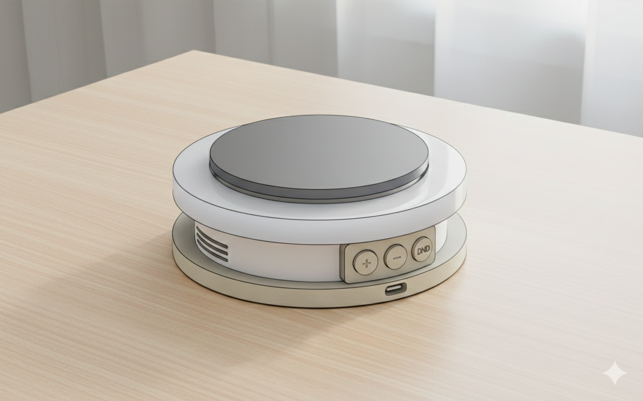
So, I wanted to create an coaster with a simple design.
These below are my parameters. I calculated them properly in order for them to fit.

After that I first drawed the sketches of the top and the bottom parts with my parameters.

Later, I drawed the sketch of the walls on the side.

I then extruded all of them based on their parameters.

I also opened a hole for the Type C Cable of the ESP32-S3.

My final bodies looked like this below.

I then combined the top body with the wall body, and I will print them separately, so that I will nail the bottom part.

I went back to sketches, and I wanted to add nail stopers to hold the PCB in the middle inside the coaster.
I first redefined new parameters.

I added nail stoper sketches to both top and bottom plate inside the old nail place.

I removed the nail holes inside the wall.
And this was my final sketch.

I decombine the old parts.
I extruded the new nail stoper holders.

And, I again combined the new parts together.
This is the final look of the coaster.

As a final change, I just increased the nail_stoper variable to 4mm from 3mm.
And, I filleted the top of the coaster and the electronics holes. But, I didn’t fillet inside of the coaster.

I also rotated the Type C Hole behind the OLED Screen.
Electronics Setup
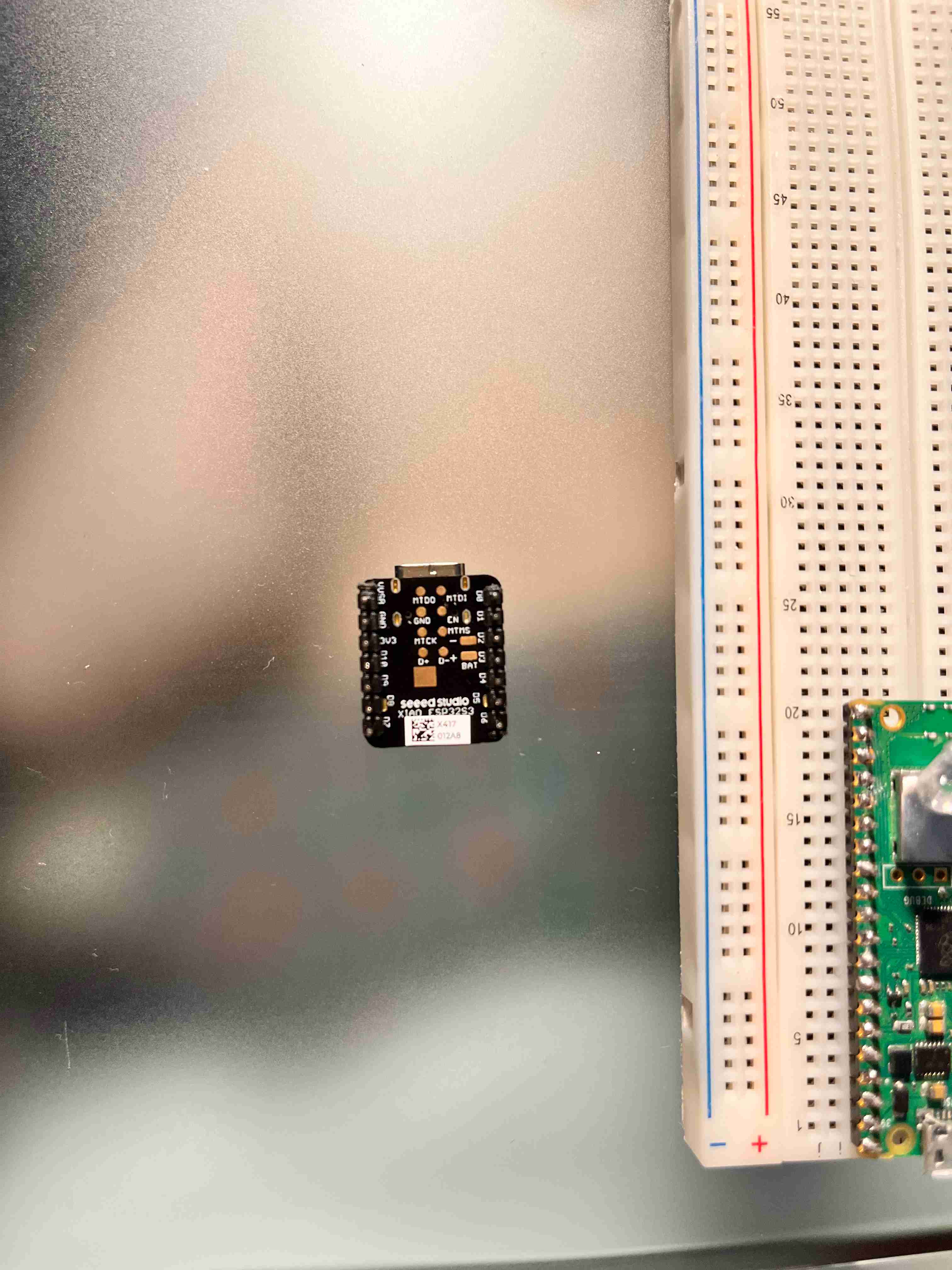
Microcontroller
XIAO SEEED ESP32-S3
For this, I first installed Arduino IDE from here:
(Download Arduino IDE From Here)
After that, in File → Preferences.
In Additional Boards Manager URLs, I added this url in order download all packages for my ESP: https://raw.githubusercontent.com/espressif/arduino-esp32/gh-pages/package_esp32_index.json
Then, in Tools → Board → Boards Manager
I searched esp32 and installed esp32 by Espressif Systems.
After installation, I went Tools → Board → esp32 → XIAO_ESP32S3.
I booted the ESP, and then connected the board with USB-C to my laptop.
Then I went to:
Tools → Port
I selected the new port that appeared, which was COM3
Now, my ESP was connected on COM3, and I could see it on the right below corner of Arduino IDE.
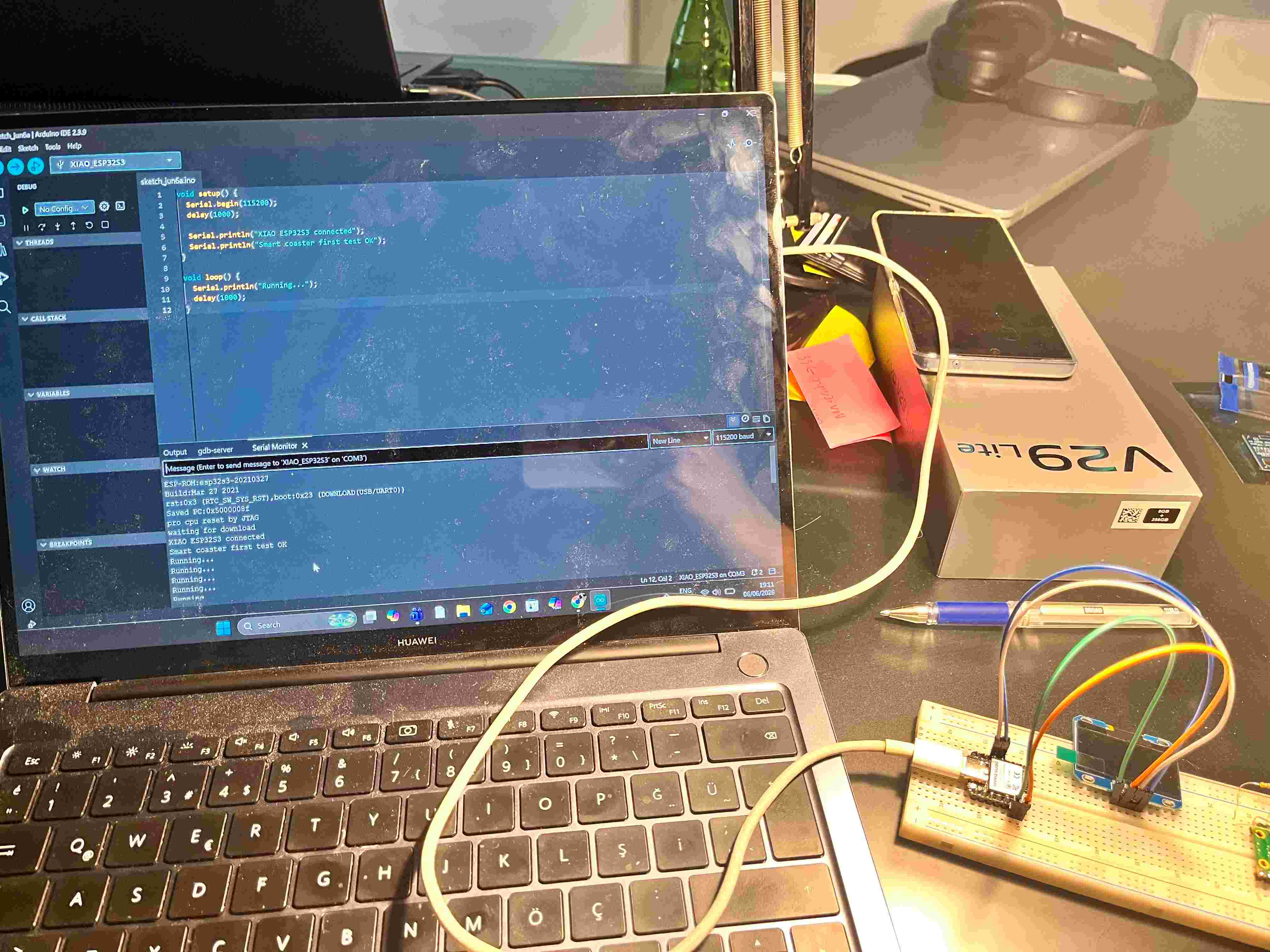
After that, I uploaded a simple Serial test first to check if the ESP is working.
void setup() {
  Serial.begin(115200);
  delay(1000);
  Serial.println("XIAO ESP32S3 connected");
}

void loop() {
  Serial.println("Smart coaster running...");
  delay(1000);
}
After uploading, I clicked on the REST button on the ESP.
And, my ESP was working:
Inputs and Outputs
Inputs
- Button (D6)
User presses it to respond to a notification
Acts as a confirmation or “acknowledge” input
Outputs
- OLED Display (D4, D5)
Displays:
Advertisements
Messages (e.g., “Order Ready”, “Waiter Coming”)
Branding / logos
- LED (D2)
- Blinks when a new message or alert arrives
- Buzzer (D3)
- Sounds when attention is required
System Behavior
The system works like this:
Message arrives →
LED starts blinking →
Buzzer starts buzzing →
Display shows message →

User presses button →
LED stops →
Buzzer stops →
System returns to idle
This creates a very clear event-response system, which is ideal for real-world environments like restaurants.
1.3 Inch Oled Screen: XFP1116-07AY
For the Oled Screen,
Tools → Manage Libraries
I searched U8g2, and installed U8g2 by oliver.
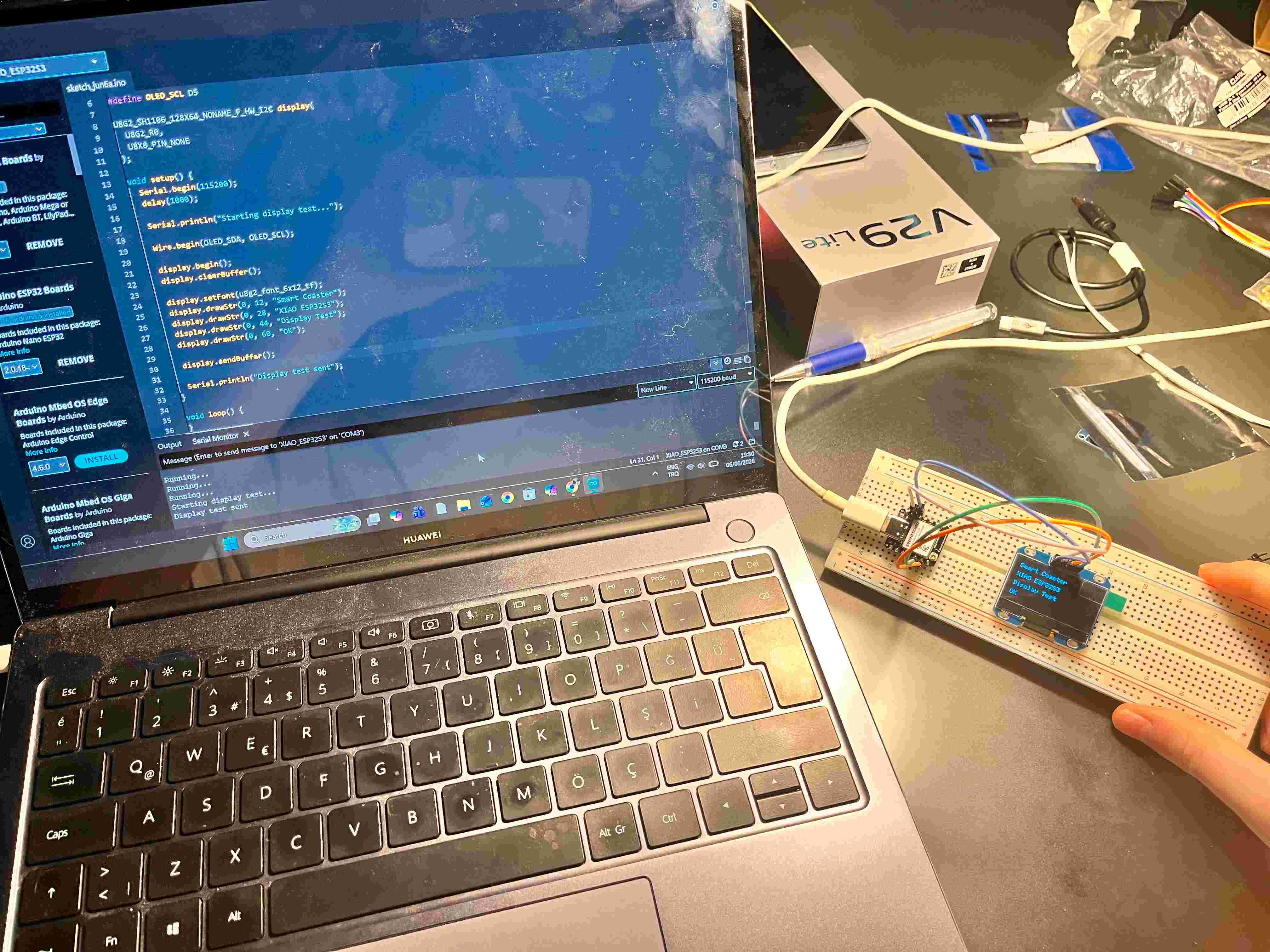
After that, I replaced my code with the one below:
#include <Arduino.h>
#include <Wire.h>
#include <U8g2lib.h>

#define OLED_SDA D4
#define OLED_SCL D5

U8G2_SH1106_128X64_NONAME_F_HW_I2C display(
  U8G2_R0,
  U8X8_PIN_NONE
);

void setup() {
  Serial.begin(115200);
  delay(1000);

  Serial.println("Starting display test...");

  Wire.begin(OLED_SDA, OLED_SCL);

  display.begin();
  display.clearBuffer();

  display.setFont(u8g2_font_6x12_tf);
  display.drawStr(0, 12, "Smart Coaster");
  display.drawStr(0, 28, "XIAO ESP32S3");
  display.drawStr(0, 44, "Display Test");
  display.drawStr(0, 60, "OK");

  display.sendBuffer();

  Serial.println("Display test sent");
}

void loop() {
}
Make sure that your board is Board: XIAO_ESP32S3 and Port: COM3.
After this, I started with my wiring.
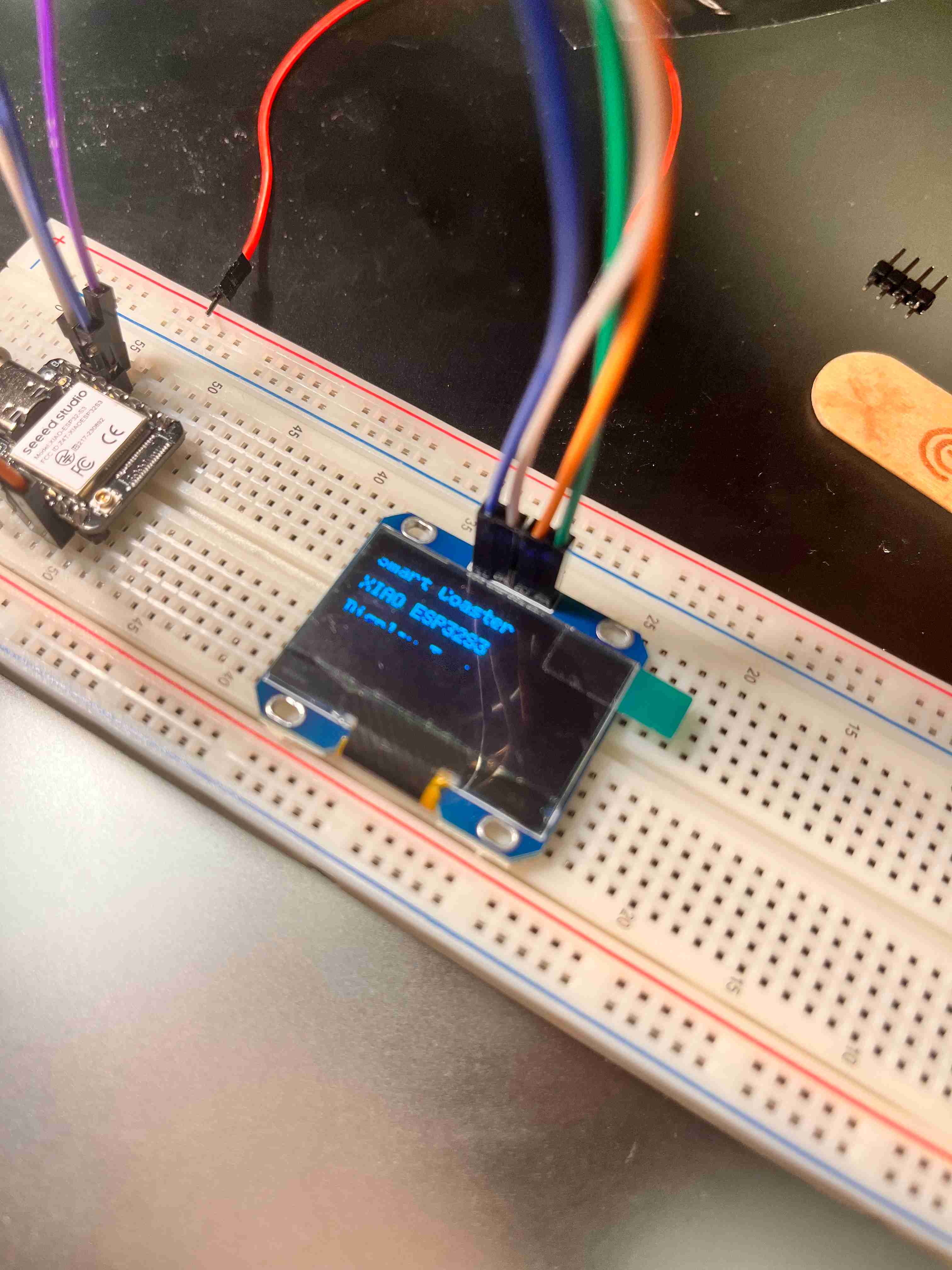
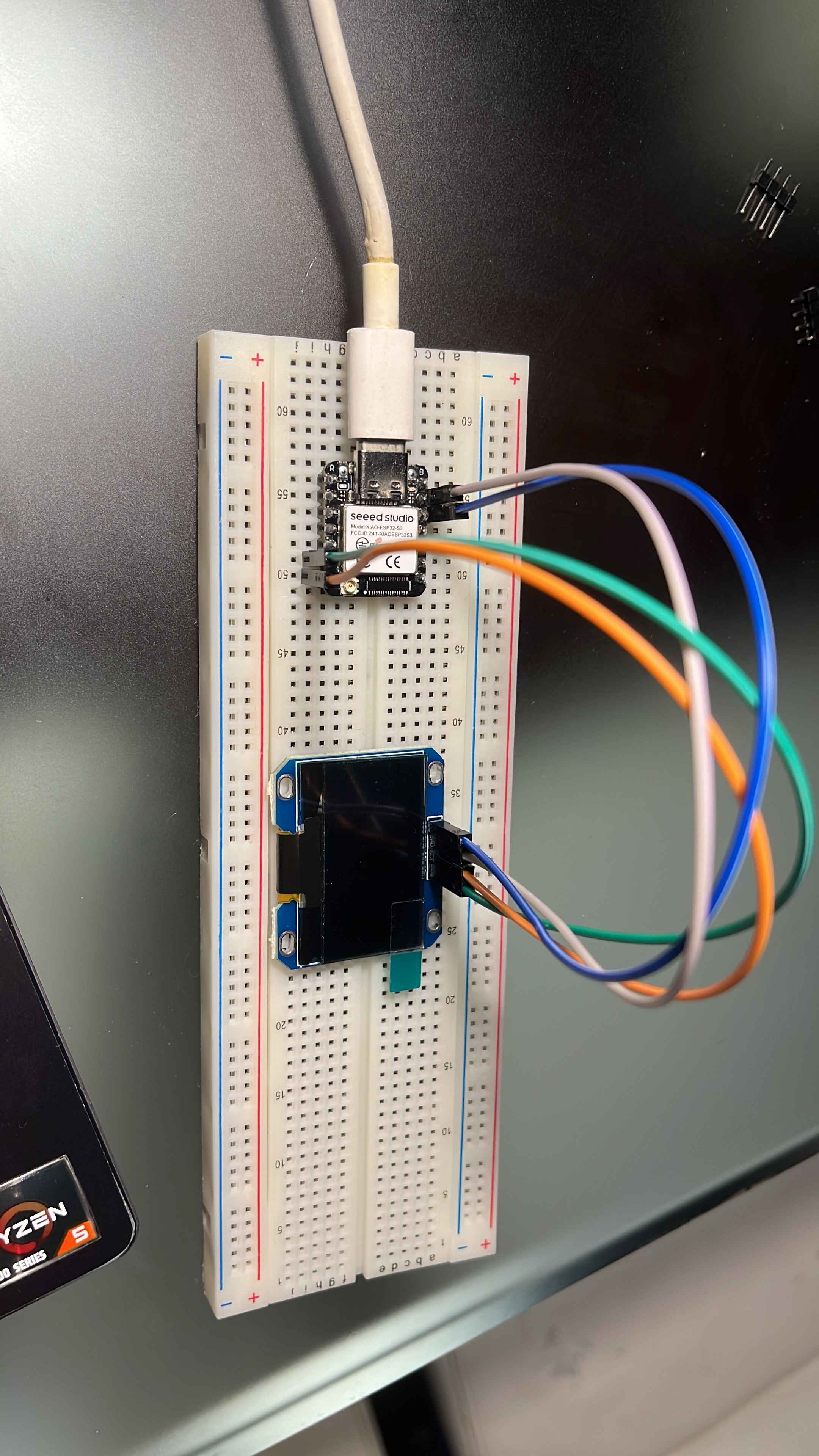
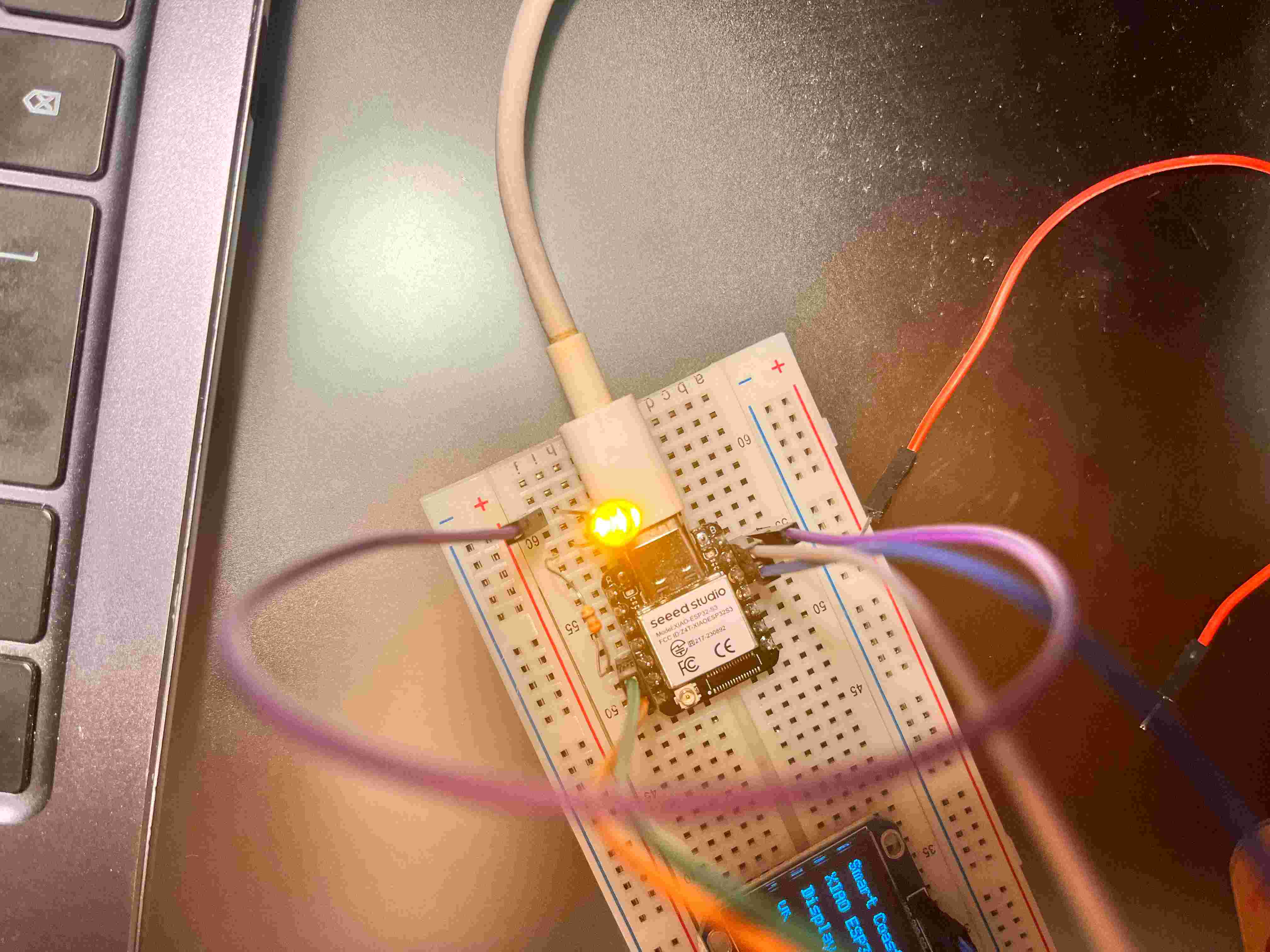
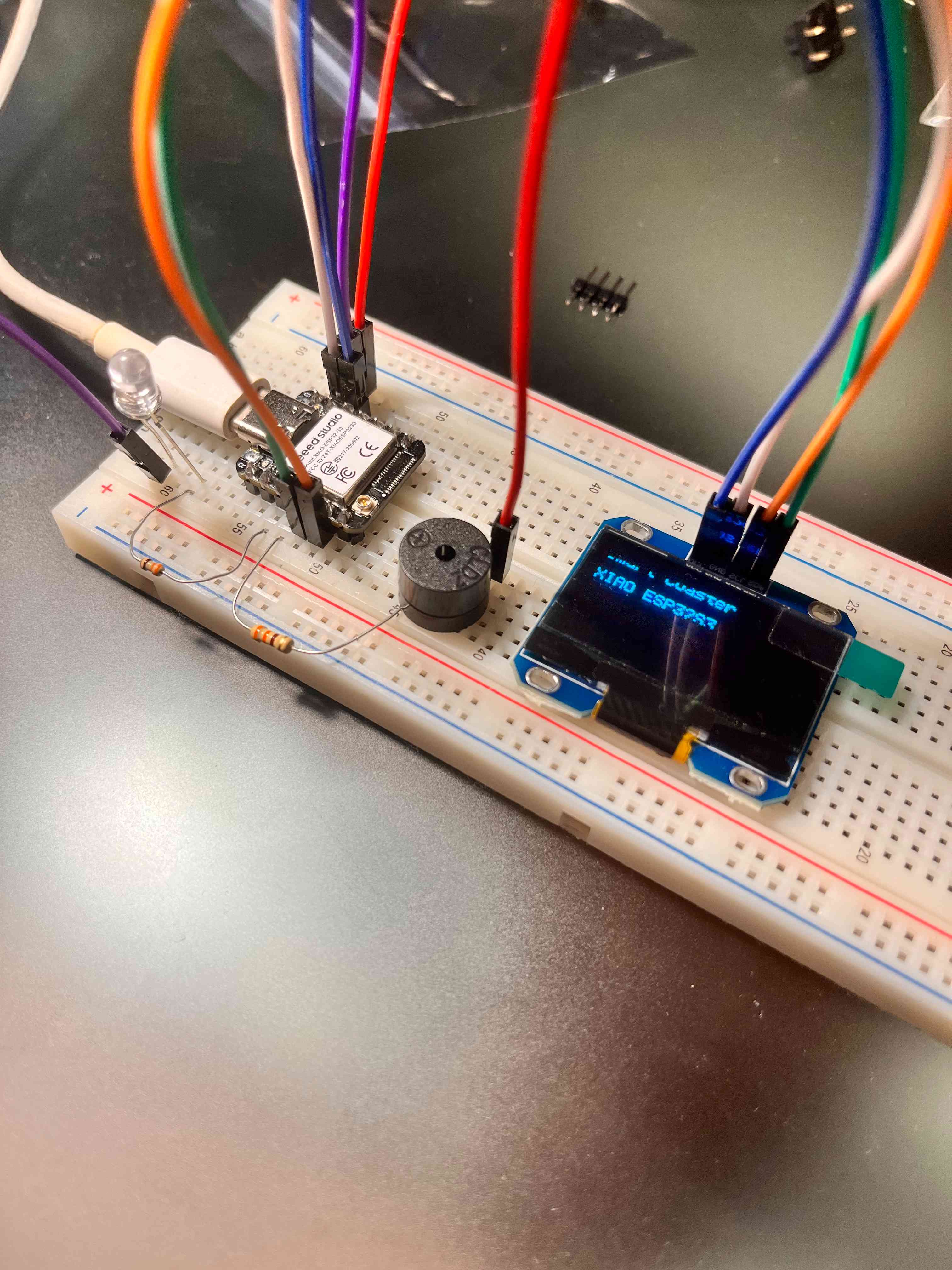
I wired Oled Screen to XIAO ESP32S3 as written below:
Display VCC → XIAO 3V3
Display GND → XIAO GND
Display SDA → XIAO D4 / SDA
Display SCL → XIAO D5 / SCL
Reminder: Keep VCC on 3.3V, not 5V.
I also shared an image below to share my wiring:
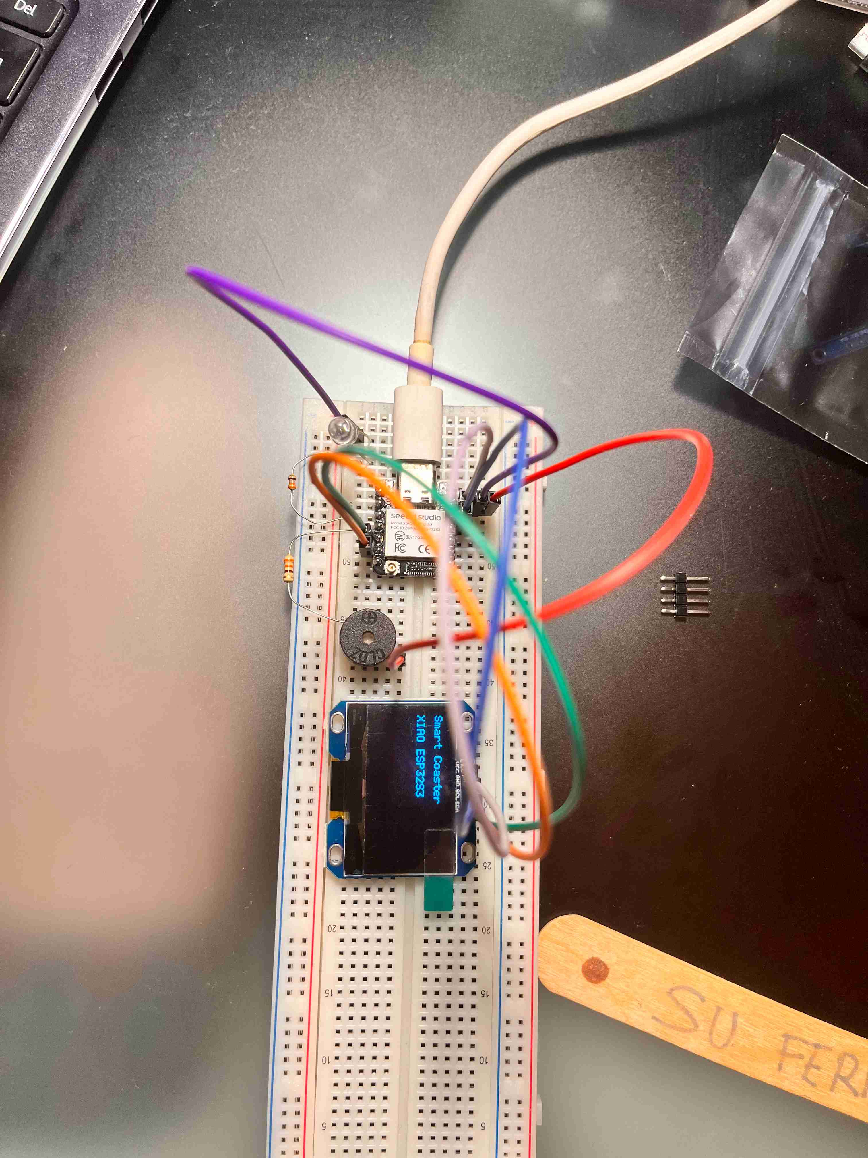
I uploaded the script to the ESP.
And, the display showed this:
Smart Coaster
XIAO ESP32S3
Display Test
OK
LED
I now wanted to test a led.
For the safety I used a 230 Ohm resistor on this one.
LED has two legs:
Long leg  = positive/anode
Short leg = negative/cathode
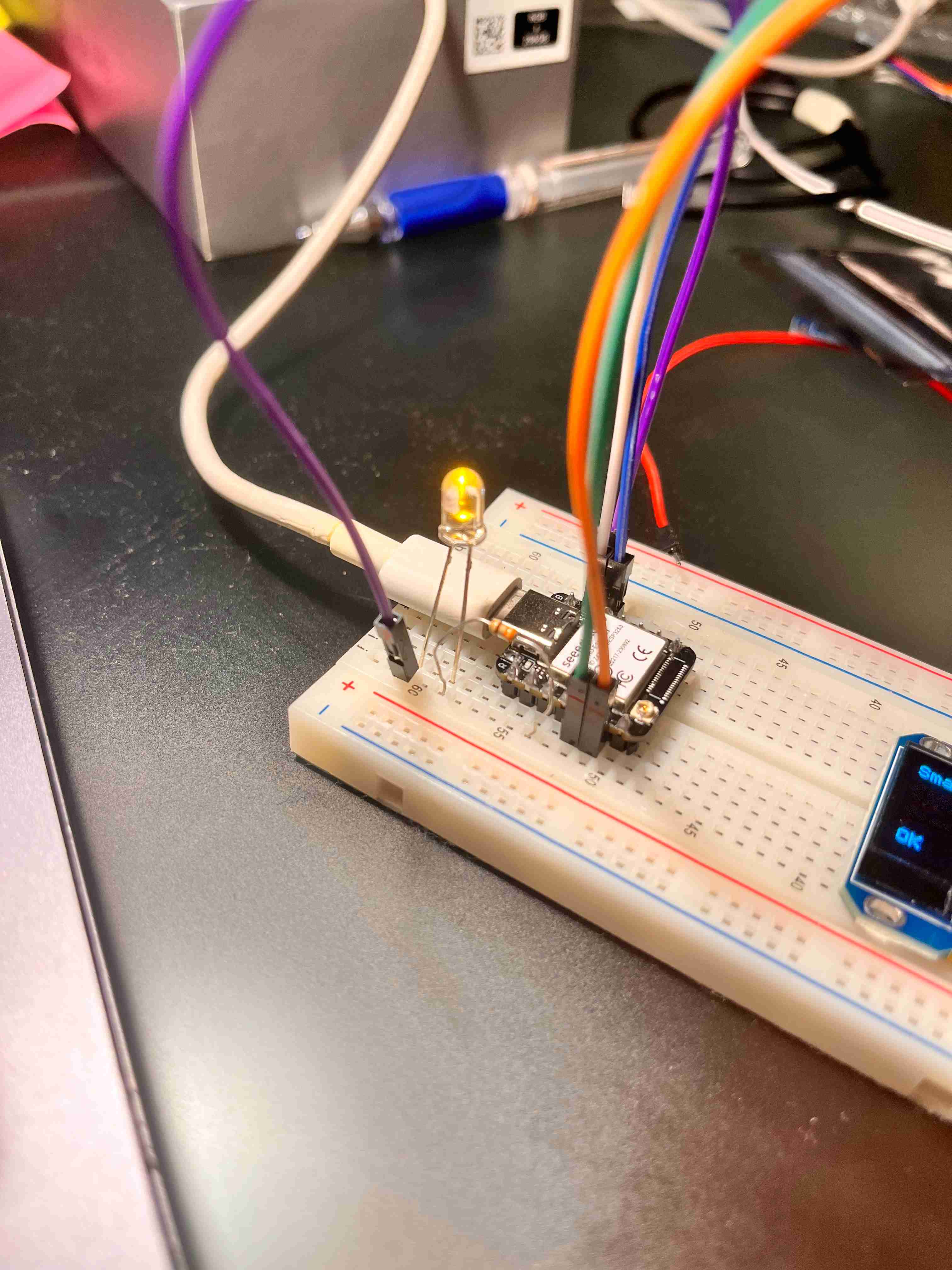
I wired it like this below:
XIAO D2  → resistor → LED long leg
LED short leg → XIAO GND
Later, I opened Arduino IDE and wrote this script:
#define LED_PIN D2

void setup() {
  pinMode(LED_PIN, OUTPUT);
}

void loop() {
  digitalWrite(LED_PIN, HIGH);  // LED on
  delay(500);

  digitalWrite(LED_PIN, LOW);   // LED off
  delay(500);
}
I clicked on upload.
After upload, the LED blinked like below:
ON  0.5 second
OFF 0.5 second
ON  0.5 second
OFF 0.5 second
You can also see it through the video.
If it does not blink, first reverse the LED legs. The LED direction matters.
Buzzer
Now, I will test out a buzzer.
I will again use a 230 Ohm resistor with this one too.
I used D3 for the buzzer.
I wired my buzzer as below:
XIAO D3  → buzzer +
XIAO GND → buzzer -
And, I kept my LED as it is.
I wrote the script below:
#define LED_PIN    D2
#define BUZZER_PIN D3

void setup() {
  pinMode(LED_PIN, OUTPUT);
  pinMode(BUZZER_PIN, OUTPUT);
}

void loop() {
  digitalWrite(LED_PIN, HIGH);
  digitalWrite(BUZZER_PIN, HIGH);
  delay(300);

  digitalWrite(LED_PIN, LOW);
  digitalWrite(BUZZER_PIN, LOW);
  delay(700);
}
I uploaded it to my ESP.
You can see how the buzzer and LED combination worked in the video below:
I realized that the sound of the was too low because of the resistor. And, since I needed a louder sound, I removed the resistor as thinking the buzzer wouldn’t consume that much of a voltage, and it would sound less when I add more stuff to the ground.
New buzzer sound video below:
Button
I also wanted to use a button to close the led and the buzzer.
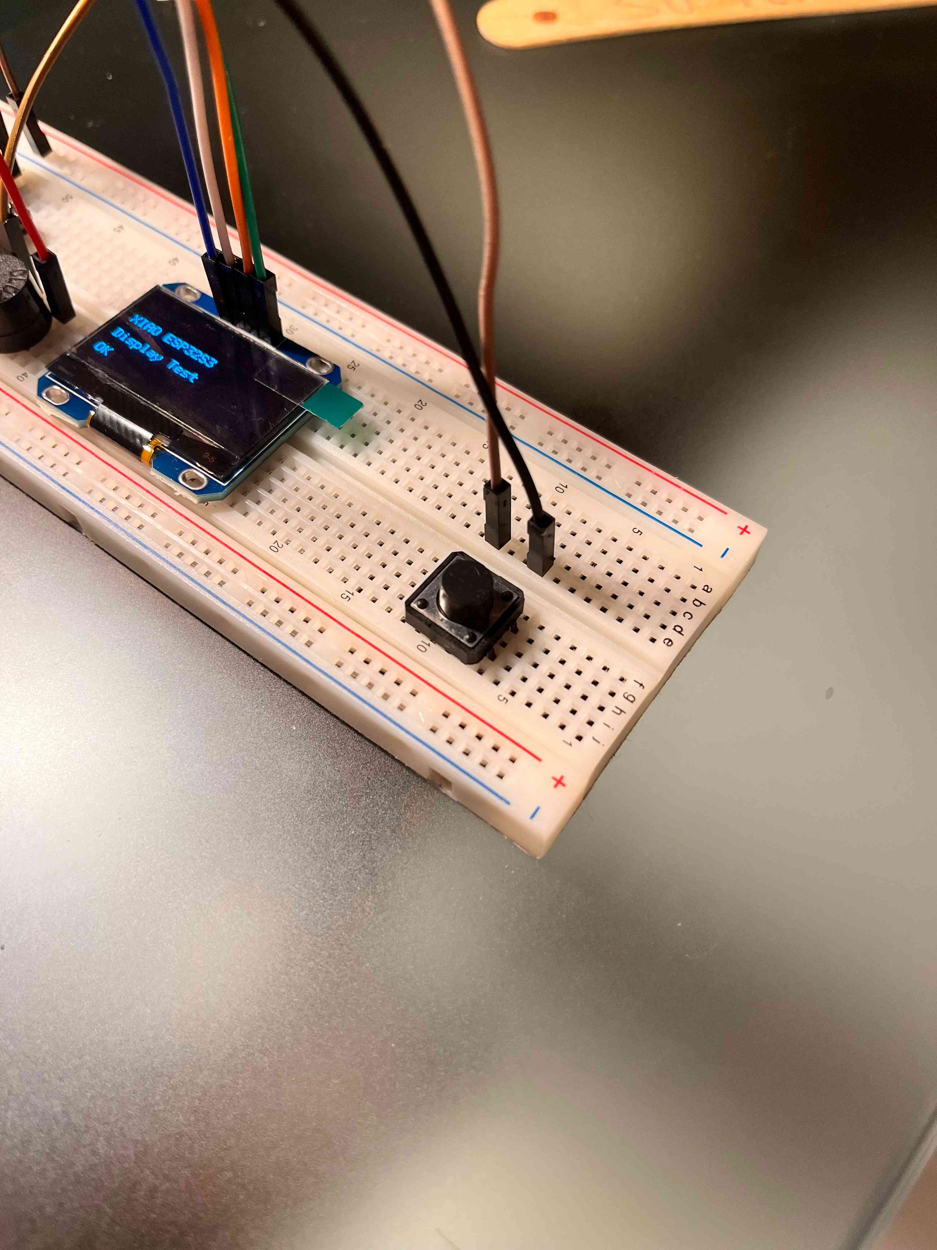
So, on this one you can wire in to ways:
Pin 1 → D6
Pin 3 → GND
or
Pin 2 → D6
Pin 4 → GND
But make sure that the pins are opposite of each other.
Here is my wiring photo:
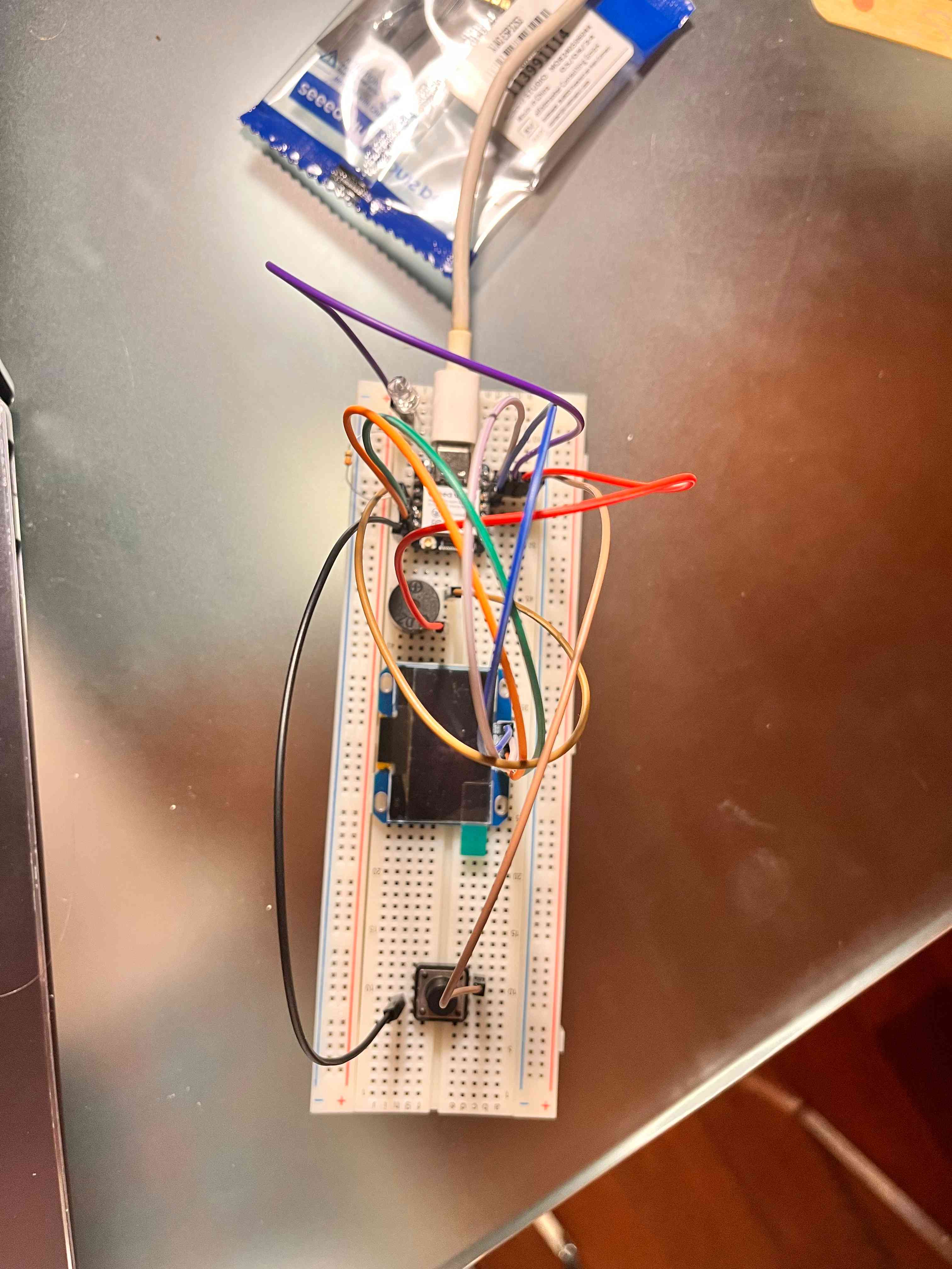
Here is the code that I used to test the button:
#define LED_PIN    D2

#define BUZZER_PIN D3

#define BUTTON_PIN D6

bool alarm_active = true;   // for now we start as if a message arrived

bool last_button_state = HIGH;

unsigned long last_button_time = 0;

const unsigned long debounce_delay = 50;

unsigned long last_blink_time = 0;

bool led_state = false;

void stop_alarm() {

  alarm_active = false;

  digitalWrite(LED_PIN, LOW);

  digitalWrite(BUZZER_PIN, LOW);

  noTone(BUZZER_PIN);

}

void setup() {

  pinMode(LED_PIN, OUTPUT);

  pinMode(BUZZER_PIN, OUTPUT);

  pinMode(BUTTON_PIN, INPUT_PULLUP);

  digitalWrite(LED_PIN, LOW);

  digitalWrite(BUZZER_PIN, LOW);

  noTone(BUZZER_PIN);

}

void loop() {

  // Read button

  bool current_button_state = digitalRead(BUTTON_PIN);

  // Detect button press: HIGH -> LOW

  if (last_button_state == HIGH && current_button_state == LOW) {

    if (millis() - last_button_time > debounce_delay) {

      stop_alarm();

      last_button_time = millis();

    }

  }

  last_button_state = current_button_state;

  // If muted/stopped, keep everything off

  if (!alarm_active) {

    digitalWrite(LED_PIN, LOW);

    digitalWrite(BUZZER_PIN, LOW);

    noTone(BUZZER_PIN);

    return;

  }

  // Alarm active: LED blinks, buzzer buzzes

  tone(BUZZER_PIN, 2000);

  if (millis() - last_blink_time >= 500) {

    led_state = !led_state;

    digitalWrite(LED_PIN, led_state ? HIGH : LOW);

    last_blink_time = millis();

  }

}
You can watch how it worked from the video below: