Week 14 – Molding and Casting
Han Ferik

Weekly Assignments:
Check Out Our Group Assignment
Group assignment:
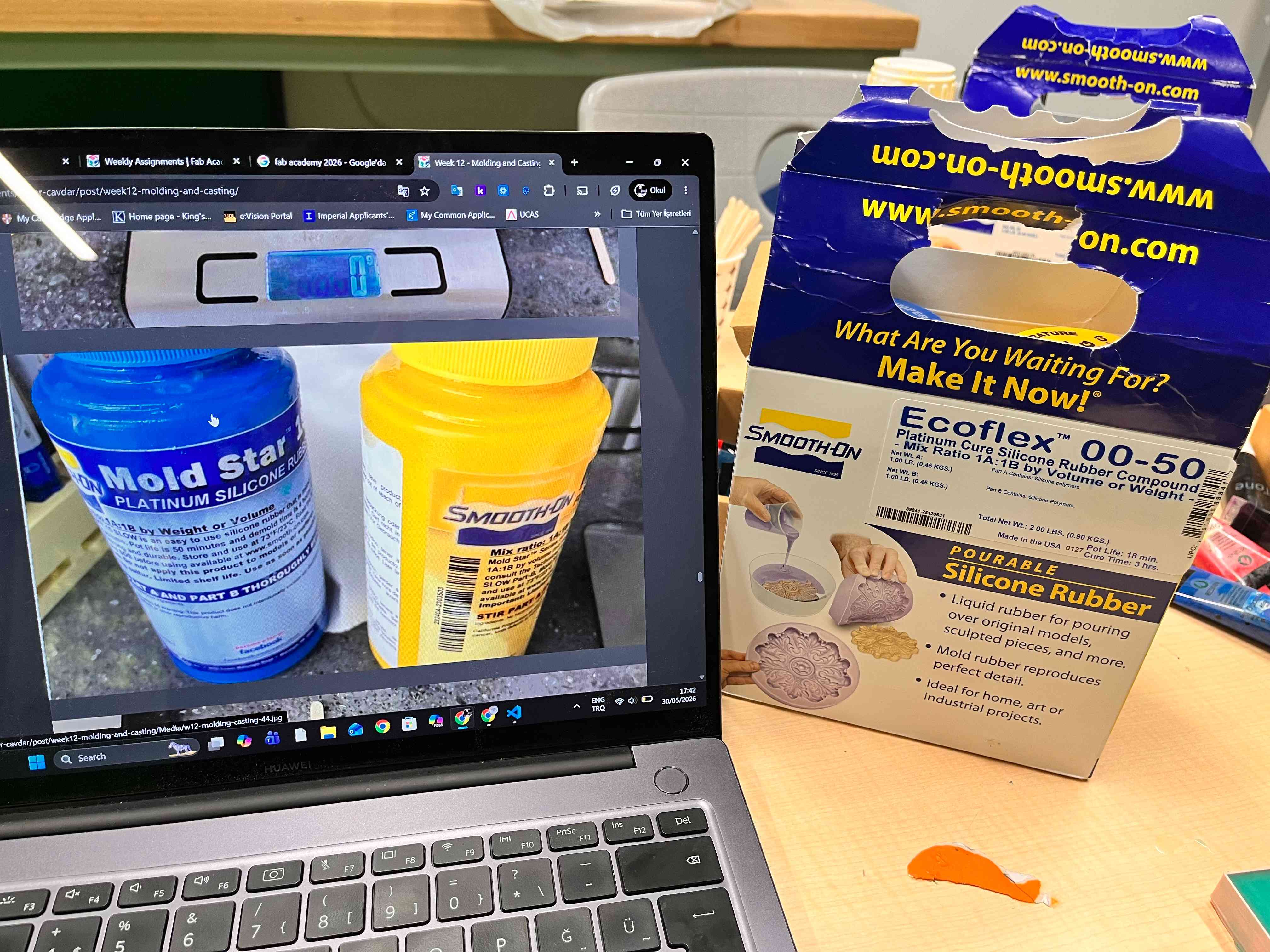
Review the safety data sheets for each of your molding and casting materials
Make and compare test casts with each of them
Compare printing vs milling molds
Individual assignment:
- Design a mold around the process you’ll be using, produce it with a smooth surface finish that does not show the production process toolpath, and use it to cast parts.
For my Moldind and Casting week, I wanted to produce a cast of the meme “67” as I make that joke a lot at school, so I wanted make a metal or at least wax cast of that with the wax mold that I make through the 3D printing.
For the mold, I will produce a totally parametric mold through 3D design and printing.
Designing the Mold with 3D Printing
I will use Fusion 360 for it. So, I opened and created a new project on Fusion 360
Designing the “67” For 3D Printing
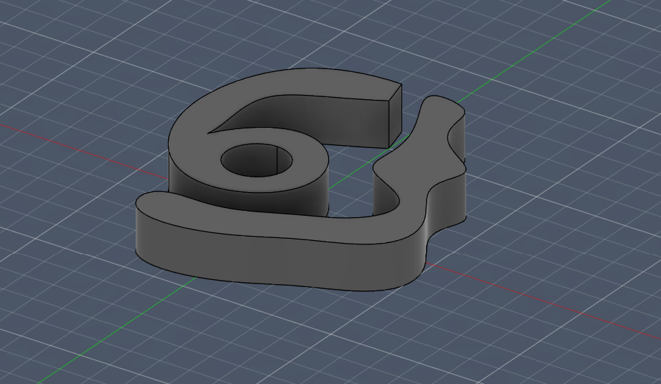
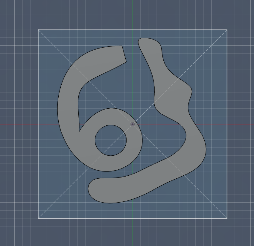
For this, I wanted it to be stylistic, so rather than just importing the images of 6 and 7, or using a text for it, I will create the 6 and 7 by using lines.
First, create a sketch on the XY plane.
And, instead of using the Text tool (which is hard to parameterize), draw the “6” and “7” using Lines and Tangent Arcs.
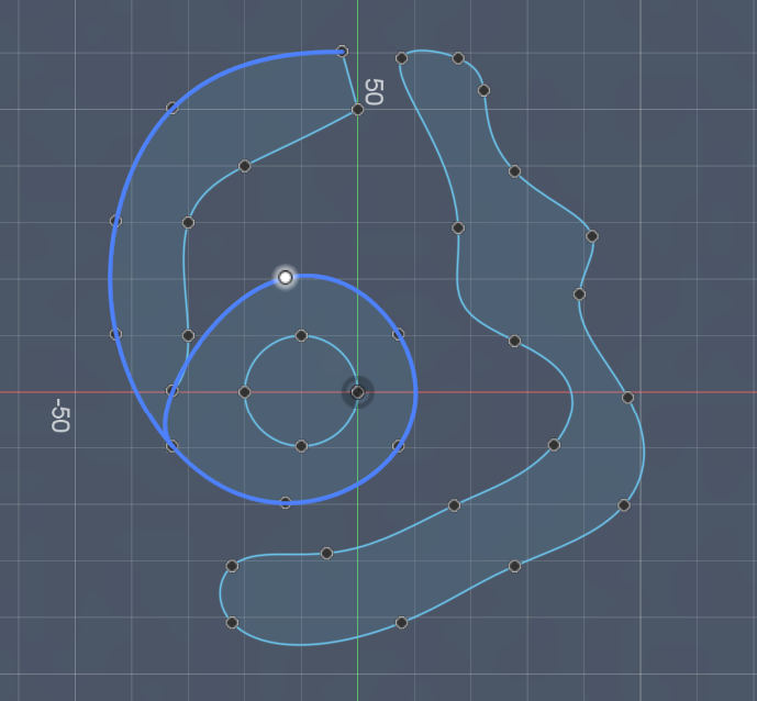
I designed my 6 like this.
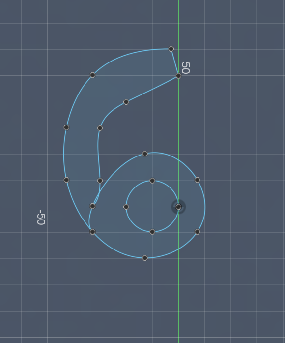
For the design of 7, I inverted it, and I titled it a little. Though, the final design does not exactly resemble of it, its still a quite cool 6 and 7.
For 2026 FAB Academy, our Lab’s friend Kris from Aalto told me that we can no longer create a mold using 3D Design, though you can see older years did that. So, further from this, please don’t follow the tutorial if your curricula doesn’t match with it. But, I will still show the later steps as future FAB Students might utilize on the future.
But, at this moment, you just need to export this as a DXF, and import it V-Carve to carve the mold inside a wax block.
Export the design as a DXF File.
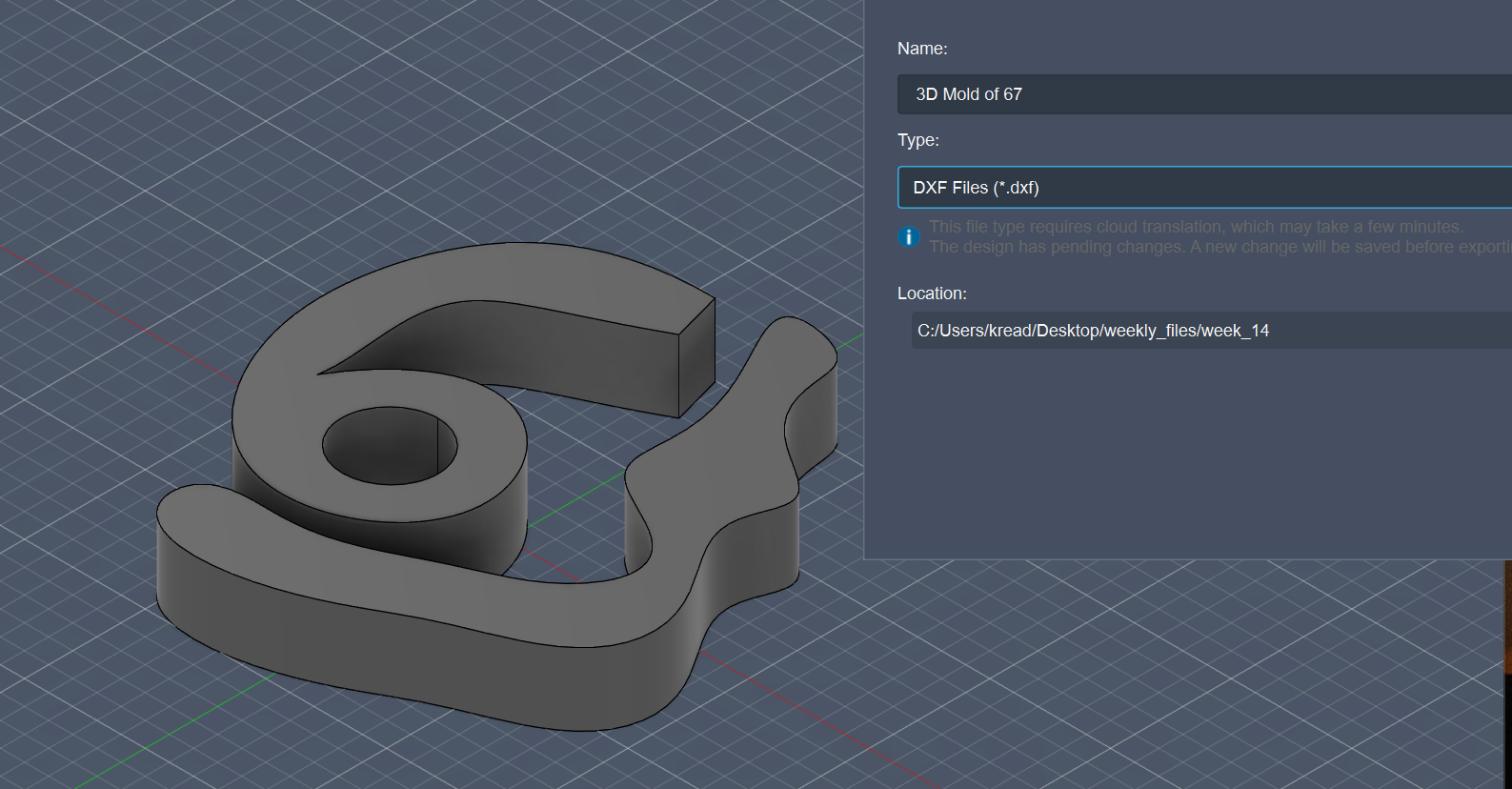
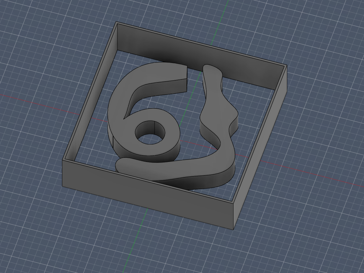
At this photo, you can see it as extruded, and it matter if its extruded or not, so I will just save you some time, we don’t want it extruded, and I only did that for the visual…
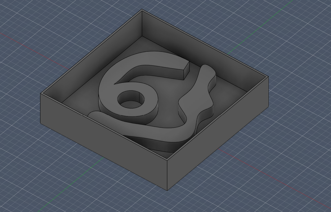
Designing the Box of “67”
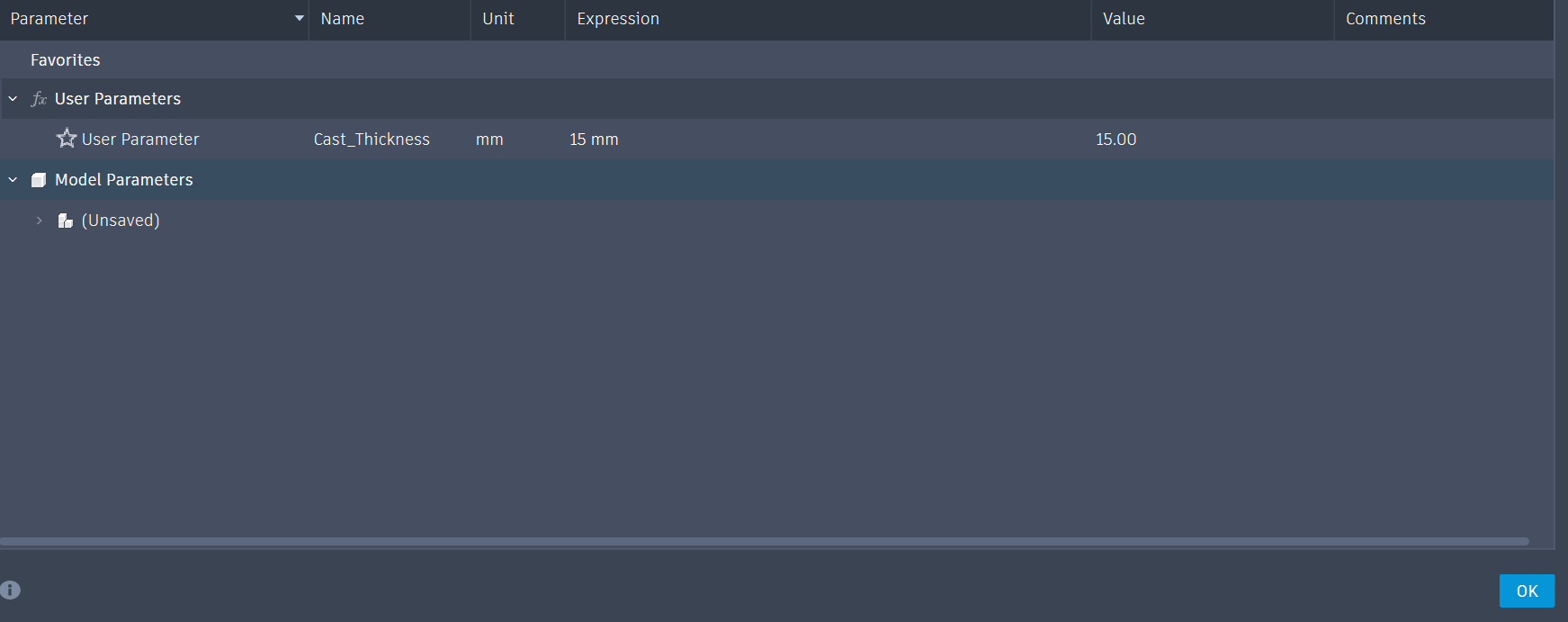
Now for the 3D Mold, set a new parameter like Cast_Thickness (e.g., 15 mm) for the thickness of the mold through Modify and Change Parameters.
After that, use the Extrude (E) command and set the distance to the new parameter Cast_Thickness.
For the 6 and 7 design inside to be in a box, create type in your parameters: Mold_Width, Mold_Depth, and Mold_Height. You can set the values of these parameters according to your design.
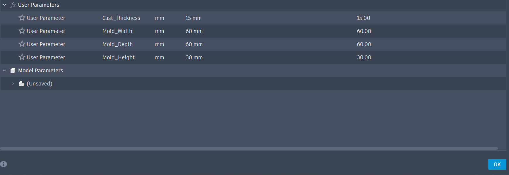
Also create a wall depth parameter for the border of the box, and set that value into your liking (e.g., 3mm).
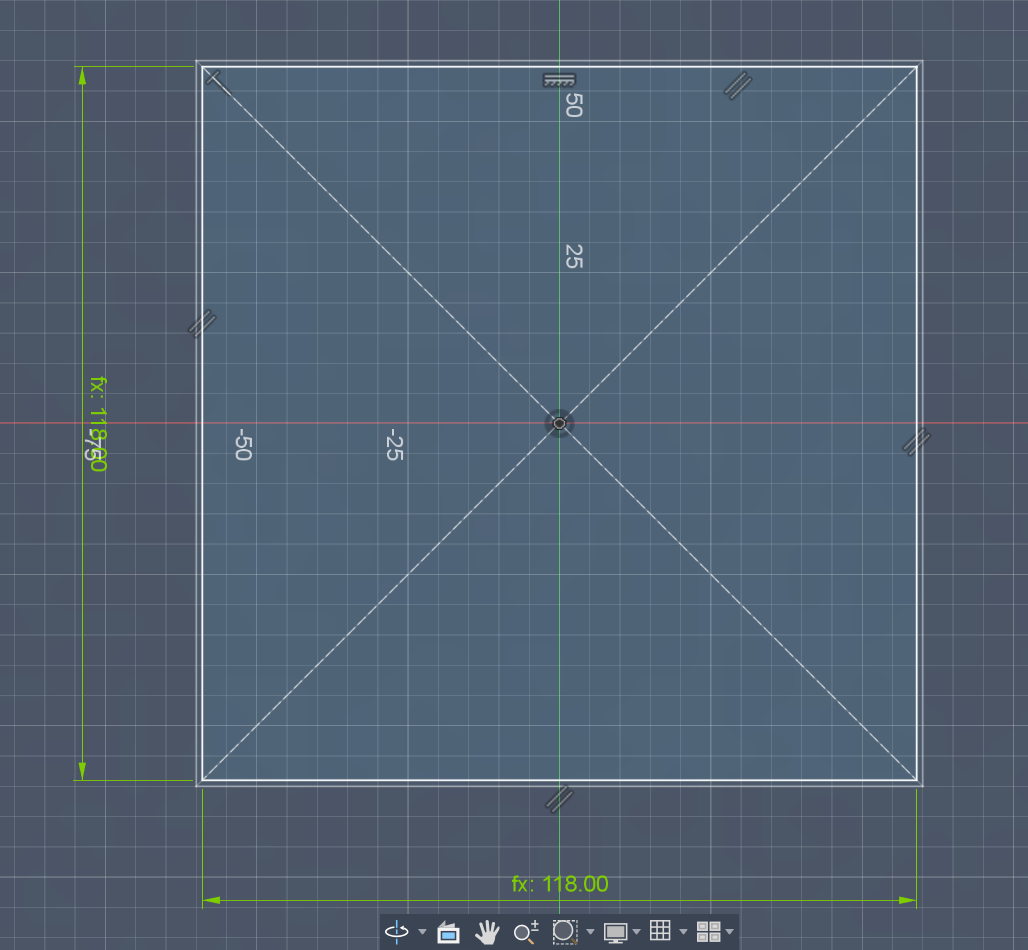
Ultimately, sketch two Center Rectangles for the border. For the first rectangle, you can set the dimensions as Mold_Depth-Wall_Depth x Mold_Width-Wall_Depth (I used 2 times the Mold_Depth and Mold_Width as my 6 and 7 design was large)
Extrude that and set the distance to the parameter Mold_Height.
Also, for your values, your Mold_Height should be greater than your Cast_Thickness, so basically it should be the double of your Mold_Height, logically.
Right now, Sketch a new Center Rectangle, and use your Mold_Depth and Mold_Width dimensions for its dimensions (I again used the 2x of those).
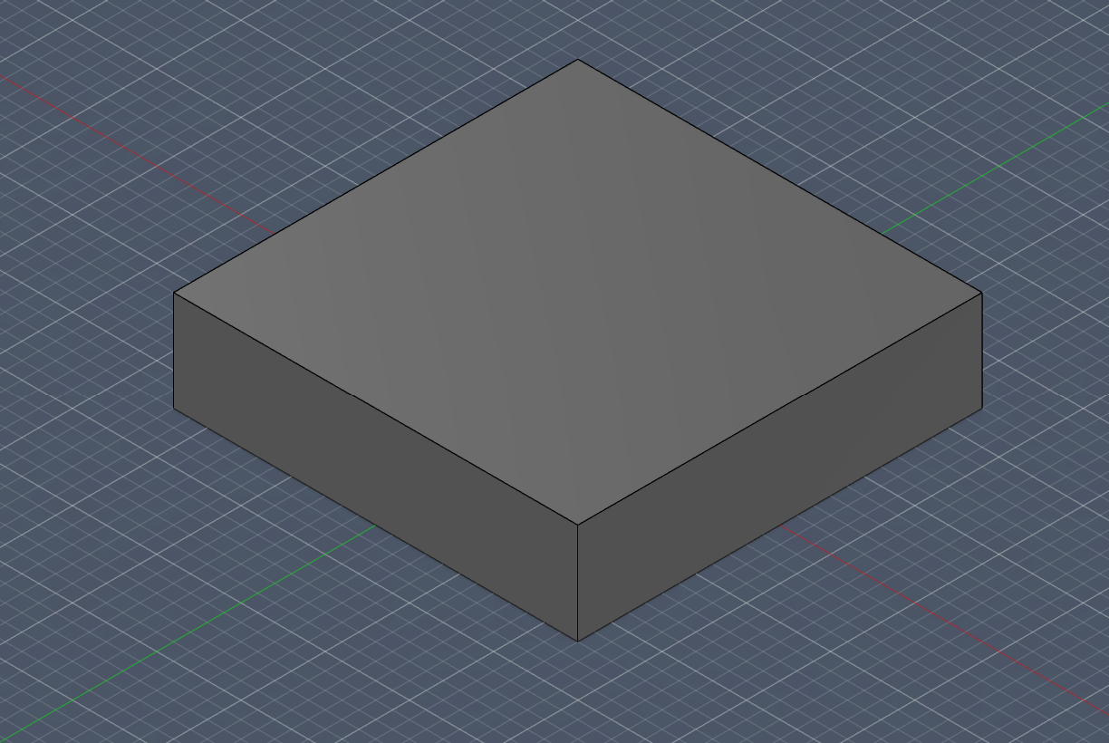
Create a new parameter like Base_Height (e.g., 5 mm)
Later, Extrude that and set the distance to the parameter Base_Height.
But, sadly, using 3D for the mold design is disallowed, still I have made the main design of it, so I wanted to how it would look when we carved it.
Designing the “67” For V Carve
Therefore, still having the old parameters, remove the last 2 extruded sketches.
Again, Create a new sketch on the bottom plane of your “67” body again with a Center Rectangle.
For the dimensions, type in your parameters: Mold_Width and Mold_Depth.
Again, Extrude this rectangle. Set the distance to Mold_Height. Also, for everything we did right now, all operations were Set to New Body..
Now, Go to Modify > Combine.
Select the Mold Block as Target Body, and Select the “67” body as Tool Bodies.
For Operation, Set to Cut.
Also, Check the Keep Tools box.
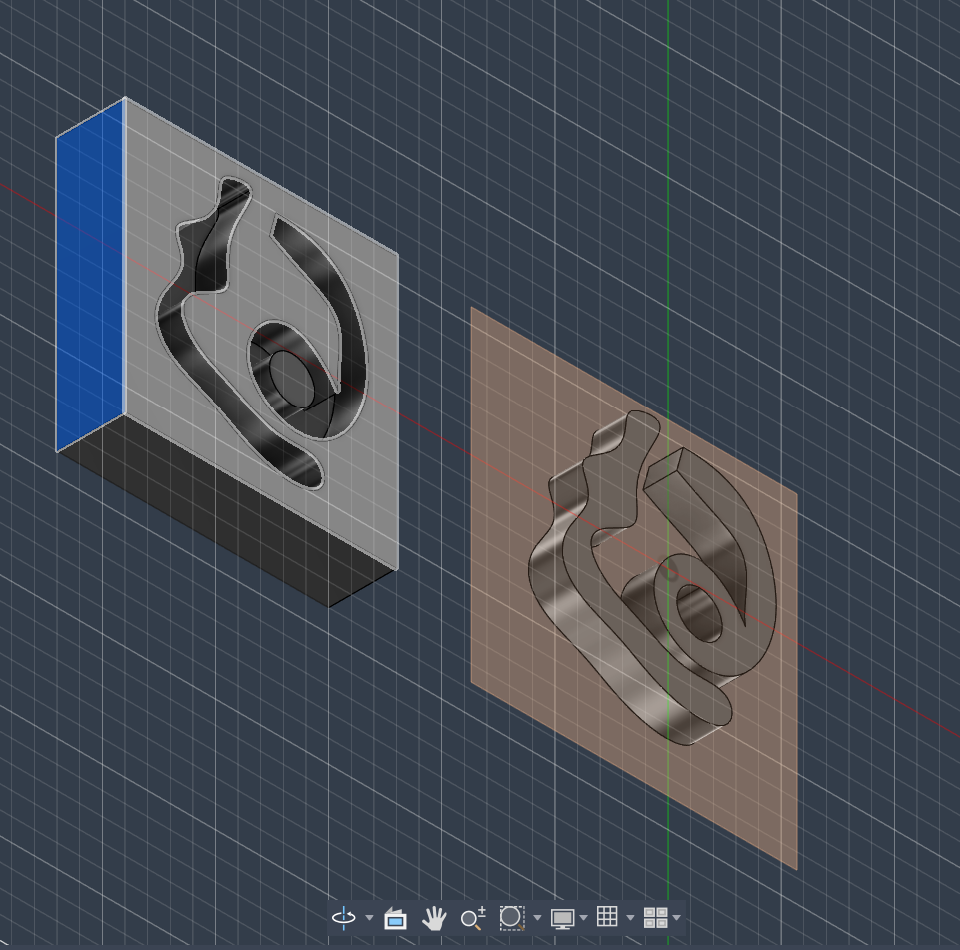
Now, Go to Construct > Midplane. Select the top and bottom faces of the mold block. This creates a plane exactly in the center.
For Split Body: Go to Modify > Split Body.
For Body to Split: choose The Mold Block.
As Splitting Tool: Choose The Midplane you just created.
Now you have a Top Half and a Bottom Half.
And, as we move the top and bottom half away, we will now see how our mold would look on the carved wax.
Carving the Mold on a Wax Block On V Carve
Below is the wax that I am going to use,
So, for this, I will use V-Carve for the carving.
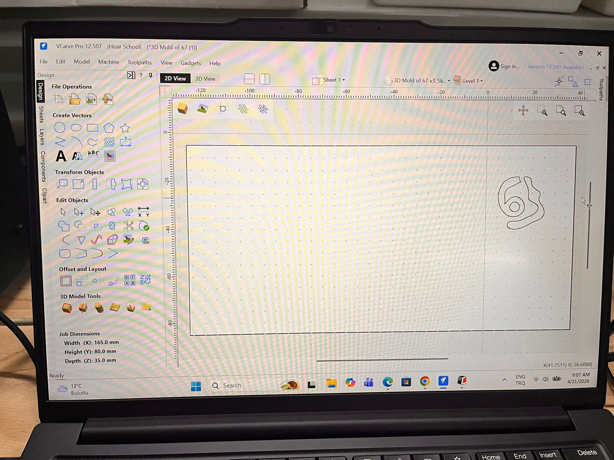
Therefore, we need to import the dxf file that we exported into V-Carve.
Job Setup
When you first import it, it will be like this.
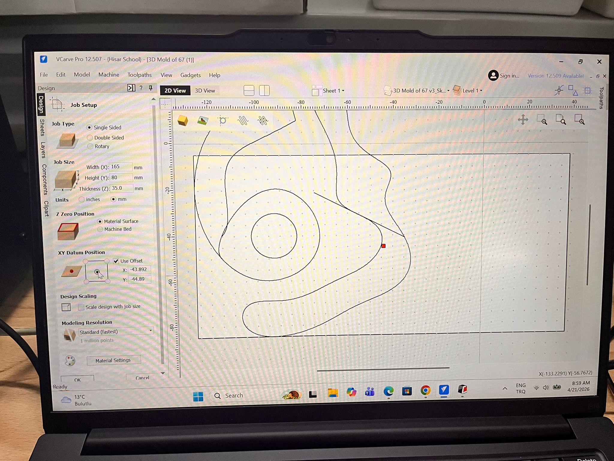
Here, when you first open VCarve and import your DXF, a “Job Setup” sidebar will appear.
For Job Size enter the width and height of your physical wax block.
For Thickness measure your wax precisely with calipers.
For Z Zero Dot select Material Surface. This is standard for wax carving.
For XY Datumchoose the Center (makes it easier to align the diagonal numbers) or the Bottom-Left corner.
And, click OK.
Preparing the Design
After that, we need to prepare the “Intertwined” Vectors
Because our numbers are close each other, VCarve might see overlapping lines. And, if we try to carve overlapping lines, the software will get confused.
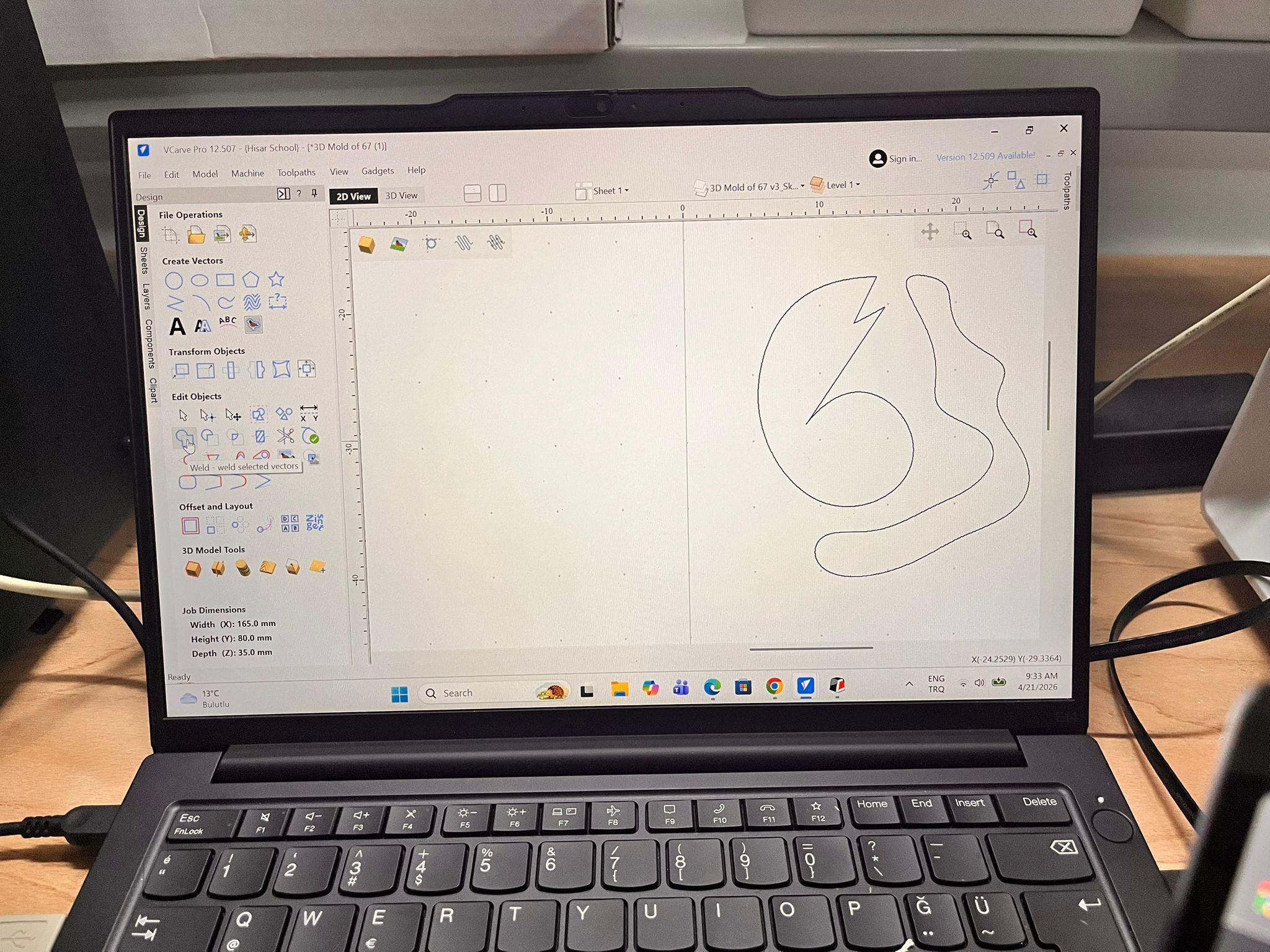
Here, Select all vectors (Ctrl+A).
Look for the “Weld” Tool: (Icon looks like two circles joined). This will merge the 6 and 7 into one single outline.
Also, if you had done Weld tool rather than trim, it would change your design when compared to trim, but you wouldn’t have to the vector validation later on.
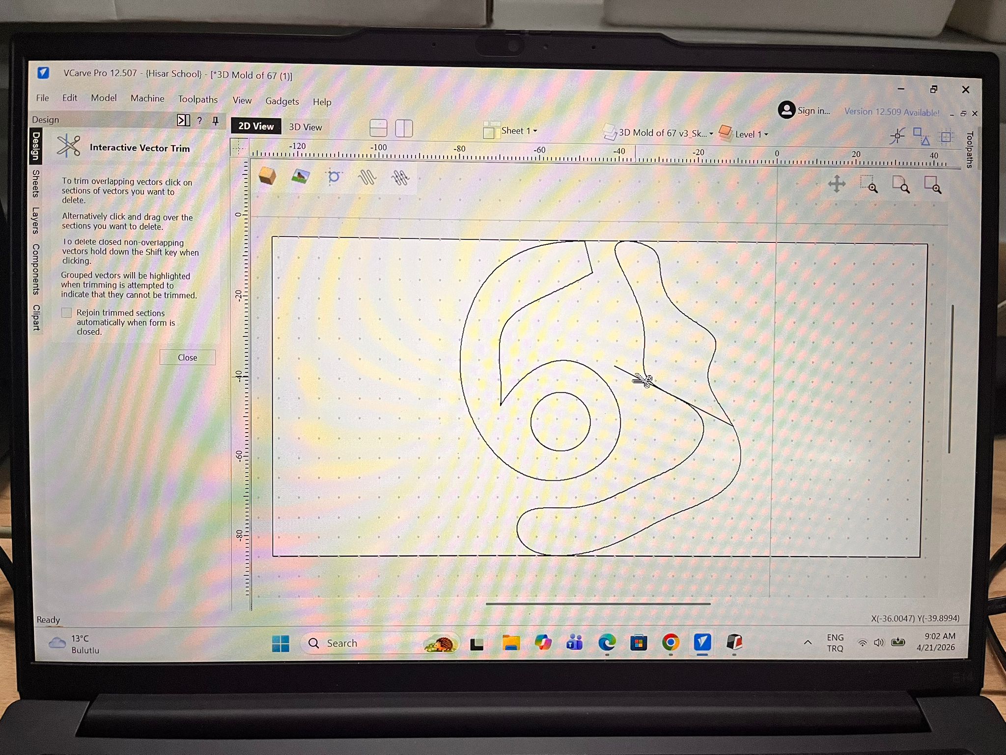
The Scissors (Trim Tool): If Weld doesn’t give the look you want, use the Interactive Trim (Scissors icon) to manually snip the lines where the 6 and 7 cross so they flow together.
I used The Scissors.
Close Vectors: Select everything and click the “Join Open Vectors” icon. VCarve needs “Closed” loops to calculate a carving.
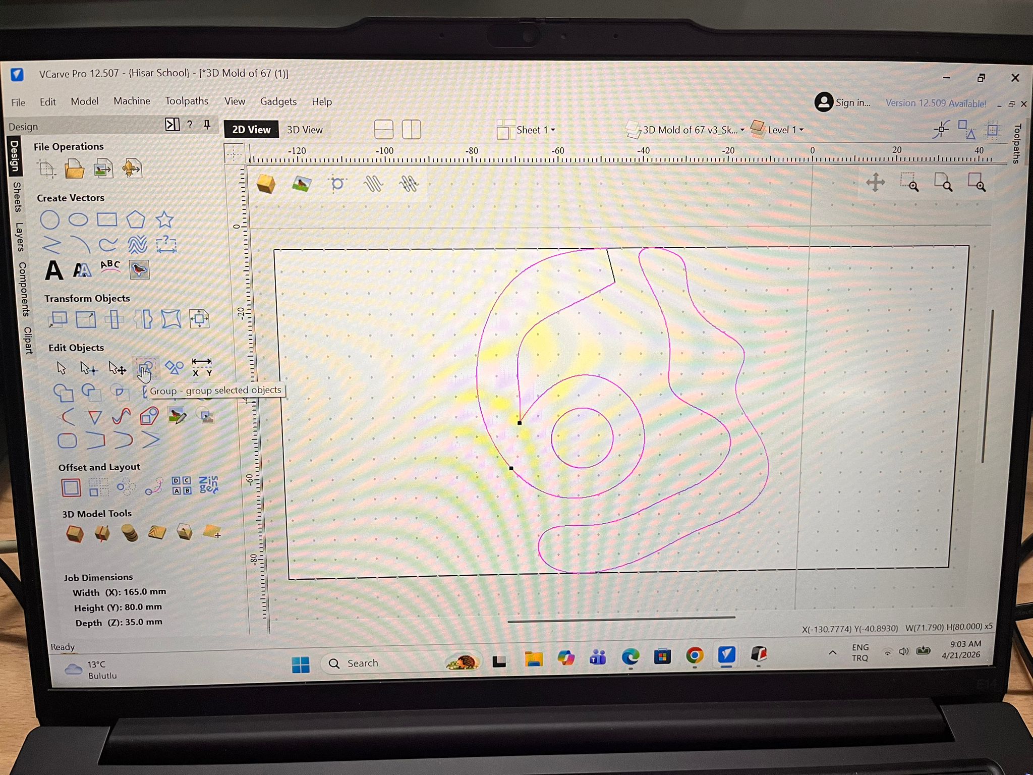
Although we intially scaled our design to the size of our job size, the design still intersected with the borders of our wax. And, that would be a problem when we offset our design. So, I further wanted to reduce its size.
Select your design.
On the left-hand Drawing Tab, look for the “Set Size” icon.
Select Scale Selection.
Either enter dimensions and change the Width (X) or Height (Y). The other dimension will update automatically to stay proportional. Or else, just drag it with your mouse.
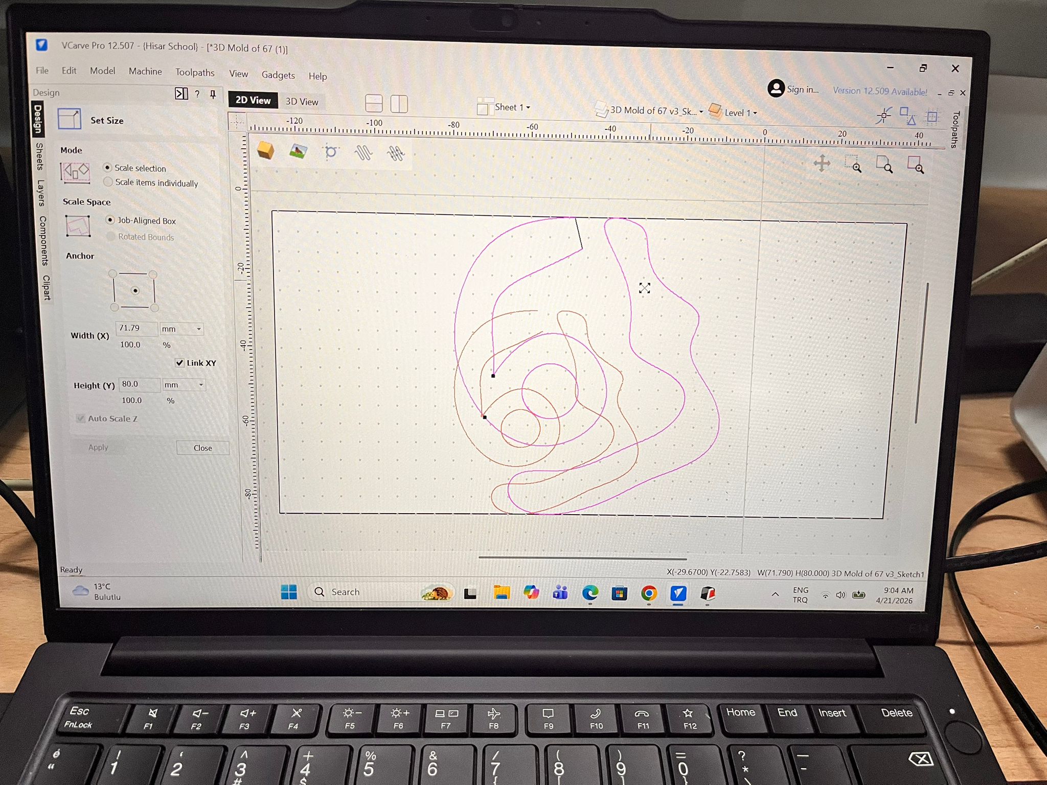
Drag your design to the place that you want to cut. Also, leave space for the offset.
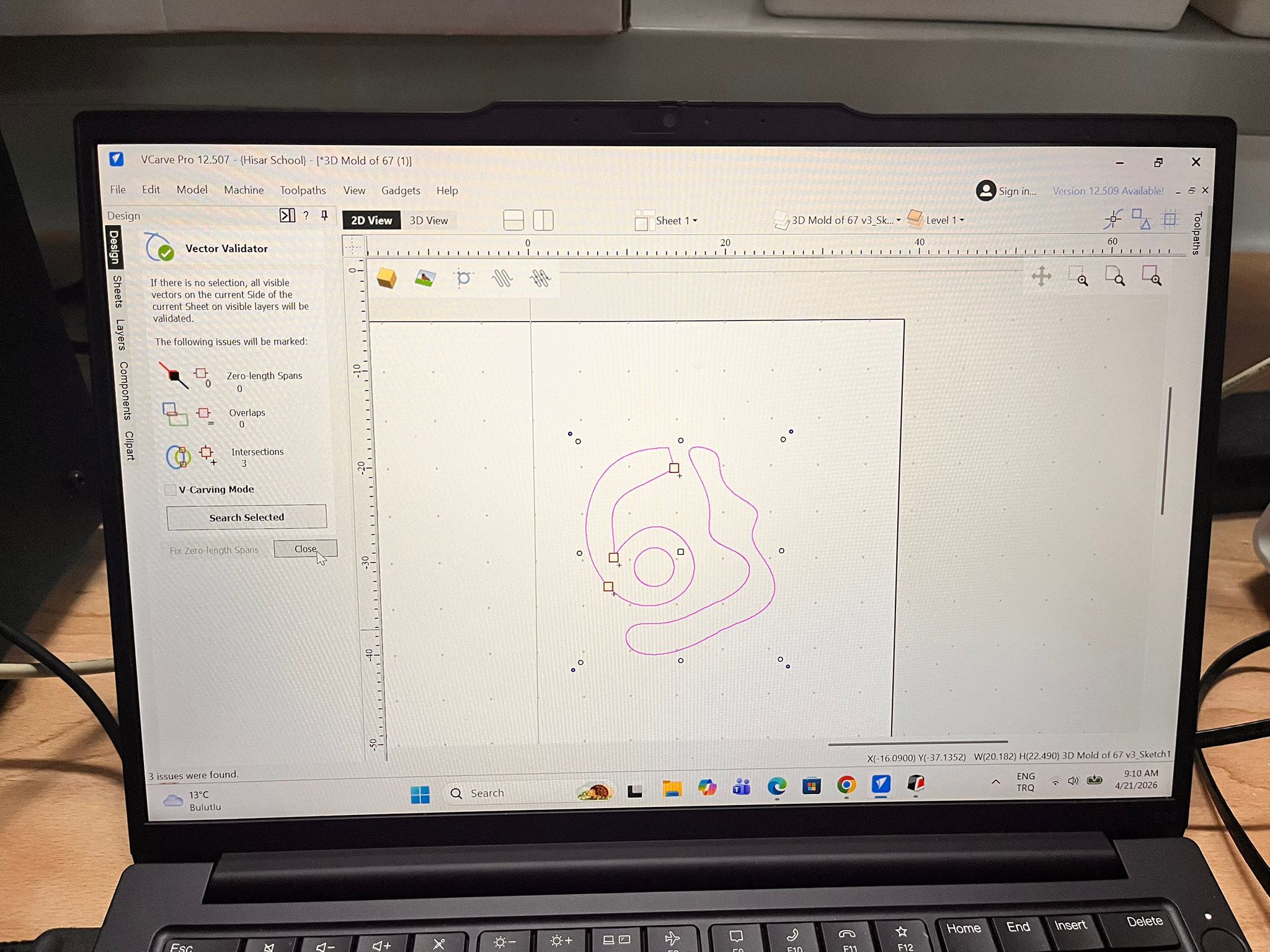
Before offseting, we locate the errors.
Before you start clicking, let VCarve show you exactly where the “illegal” overlaps are.
Select your design.
In the Edit Objects section (left sidebar), click the Vector Validator icon (it looks like a magnifying glass over a zig-zag line).
Click Search Selected.
VCarve will mark intersections with red circles. These are the spots you need to fix.
To fix,
Select both the 6 and the 7.
Click the Weld icon (two overlapping circle and square).
VCarve will ask if you want to keep the original vectors; usually, you should click No.
The overlapping internal lines will vanish, leaving one clean outer boundary. Though, the design will change a little.
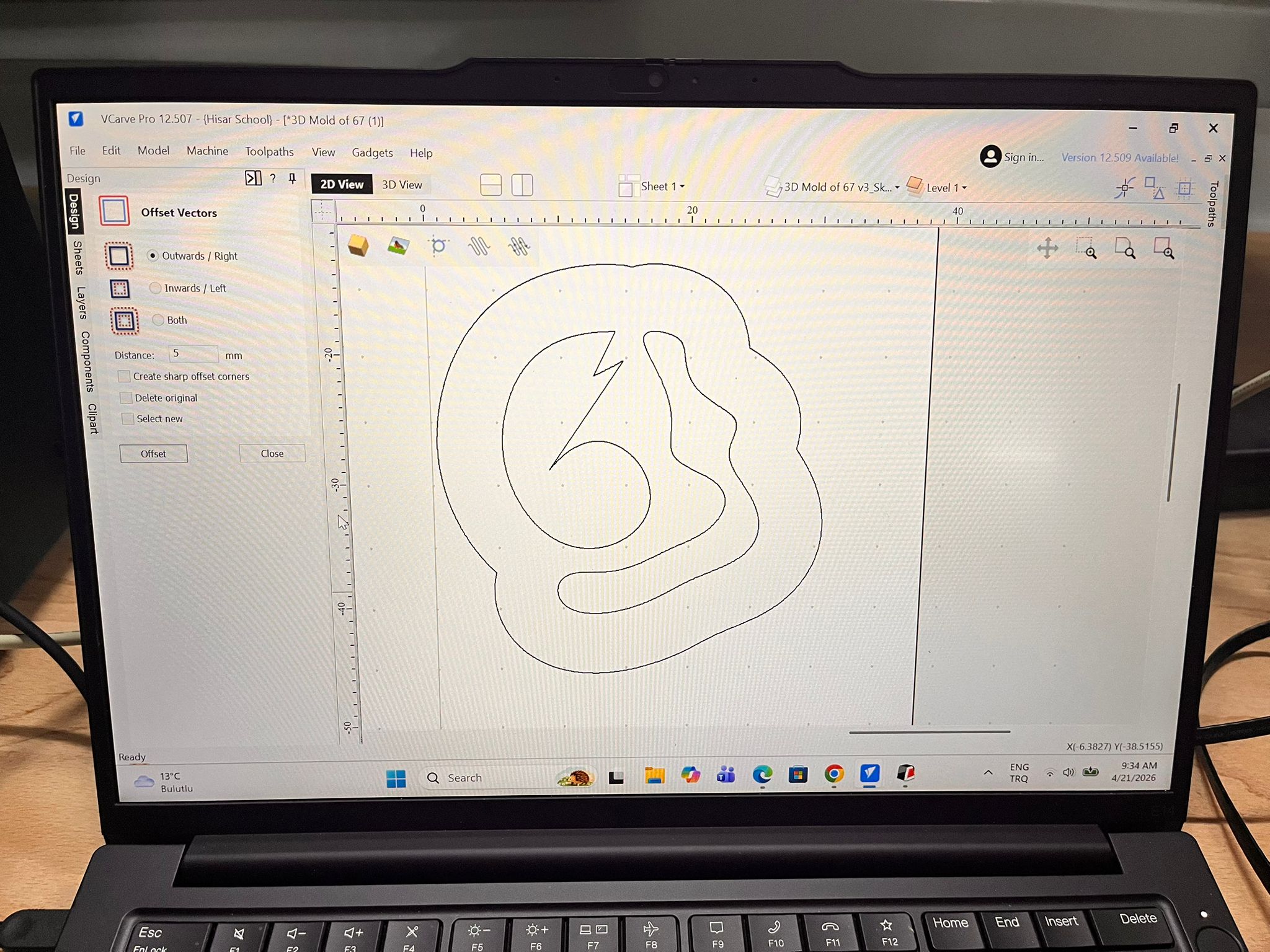
Finally, we need to offset our design.
Select your Design.
Click Offset Vectors.
Select Outwards / Right.
You can also need to select your distance. (e.g., 5 mm)
And, offset
Creating the V-Carve Toolpath
We can now move on to creating the V-Carve Toolpath.
Open Toolpaths (on the top side of the screen).
Select Show Toolpaths Tab.
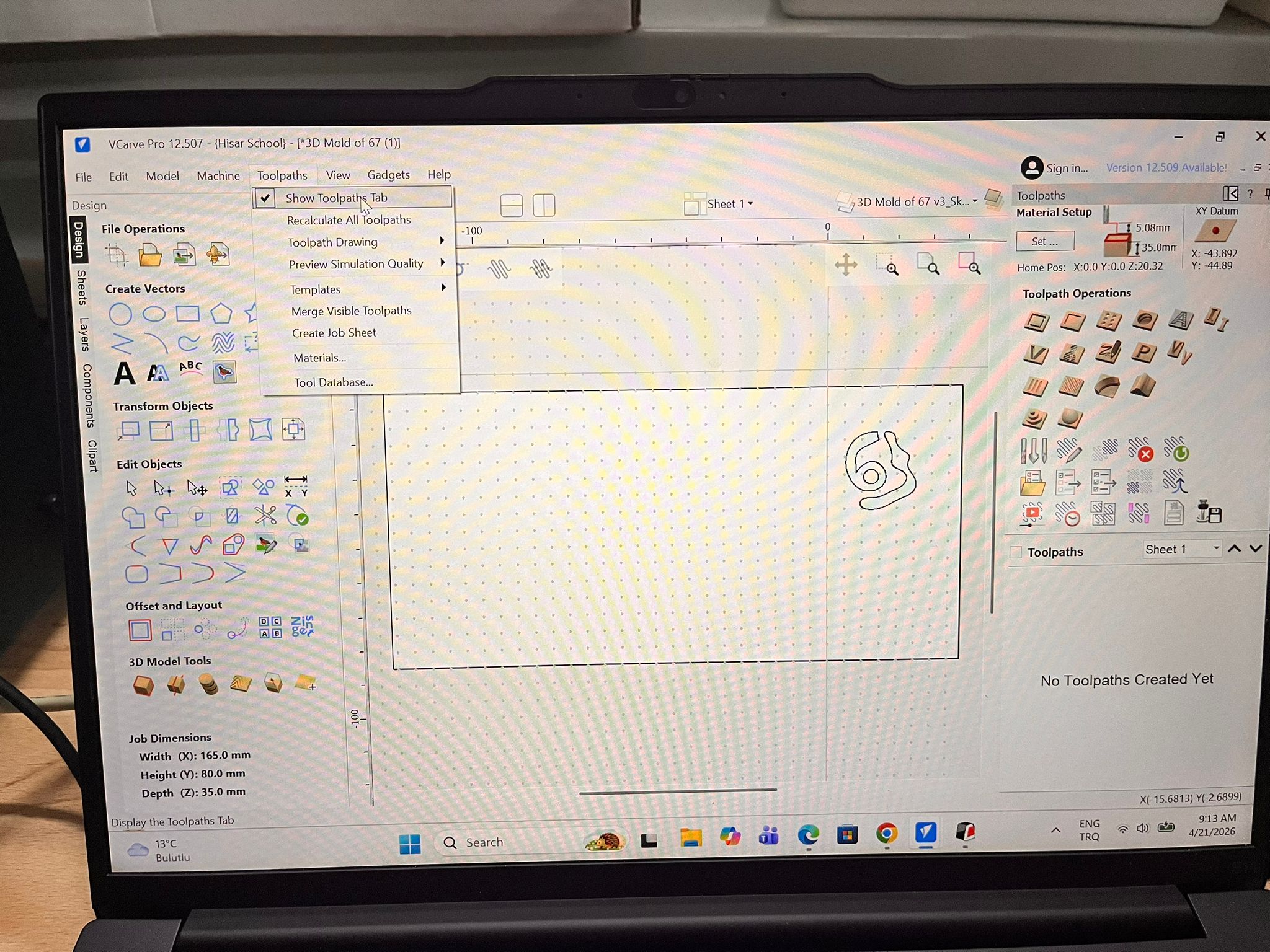
This will open your toolpaths on the right side of your screen.
After this you need to create your own tool path based on your design. I will skip this as I personally find the 3D printing easier.
Creating the Mold of the Wax Block with 3D Printing
Quality Settings
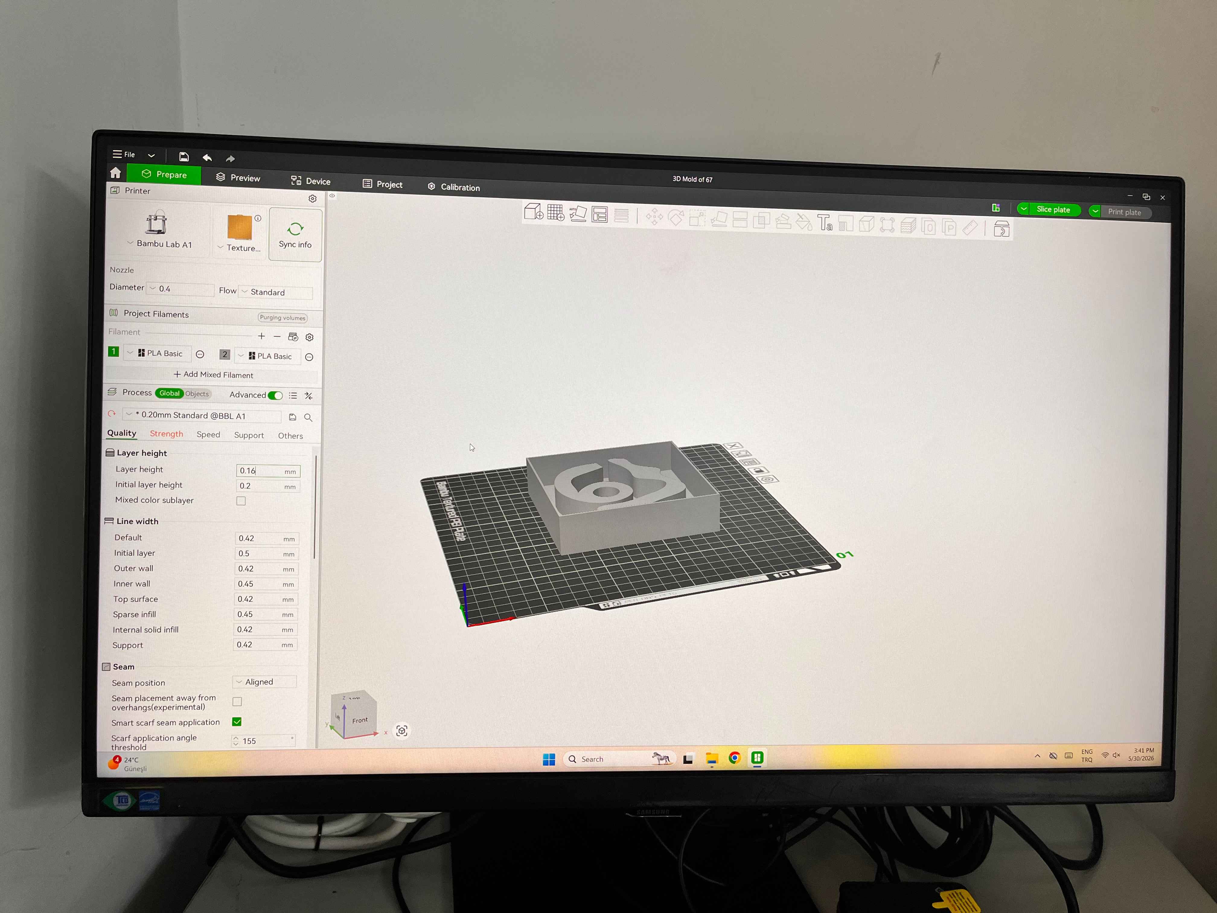
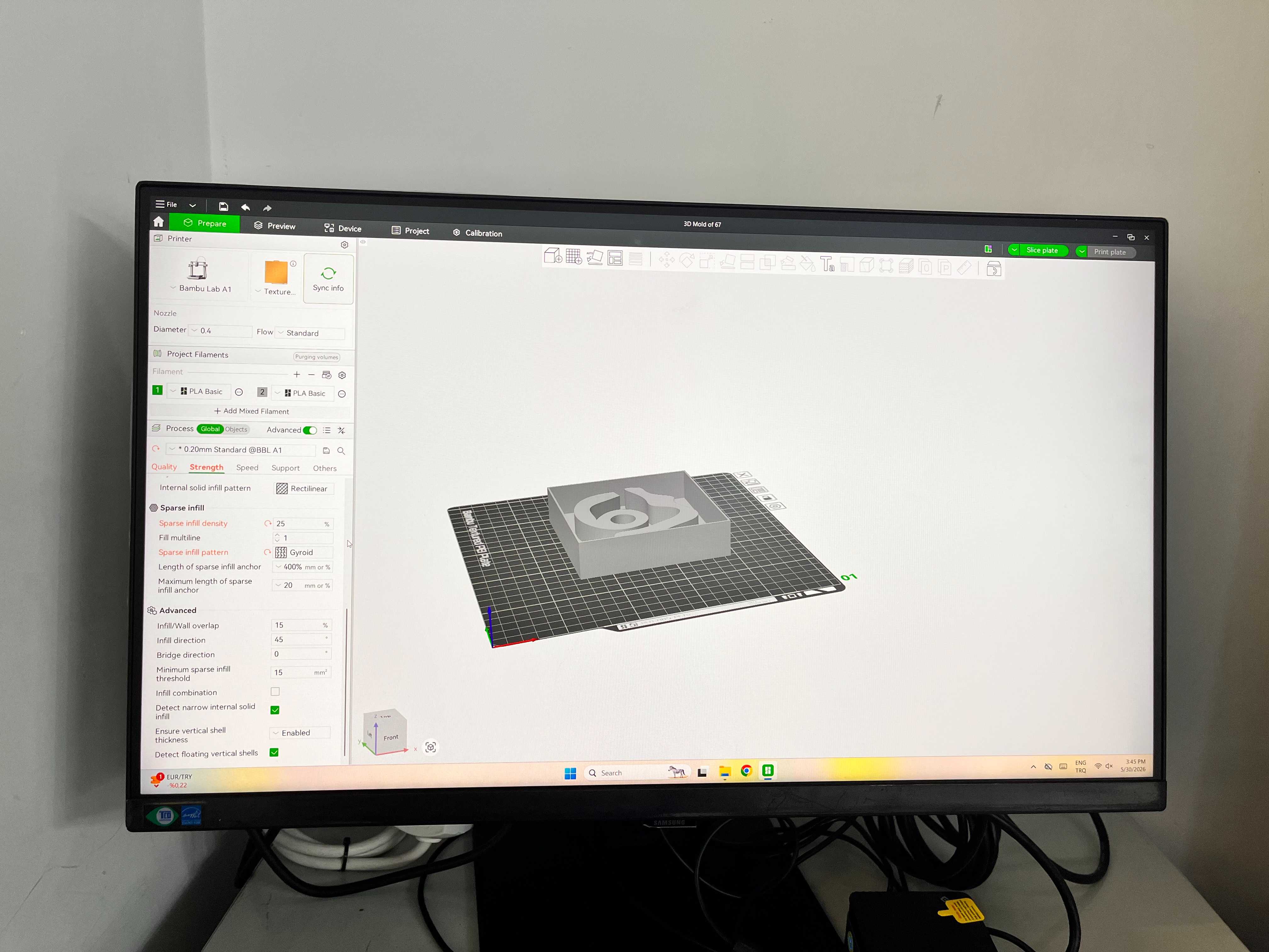
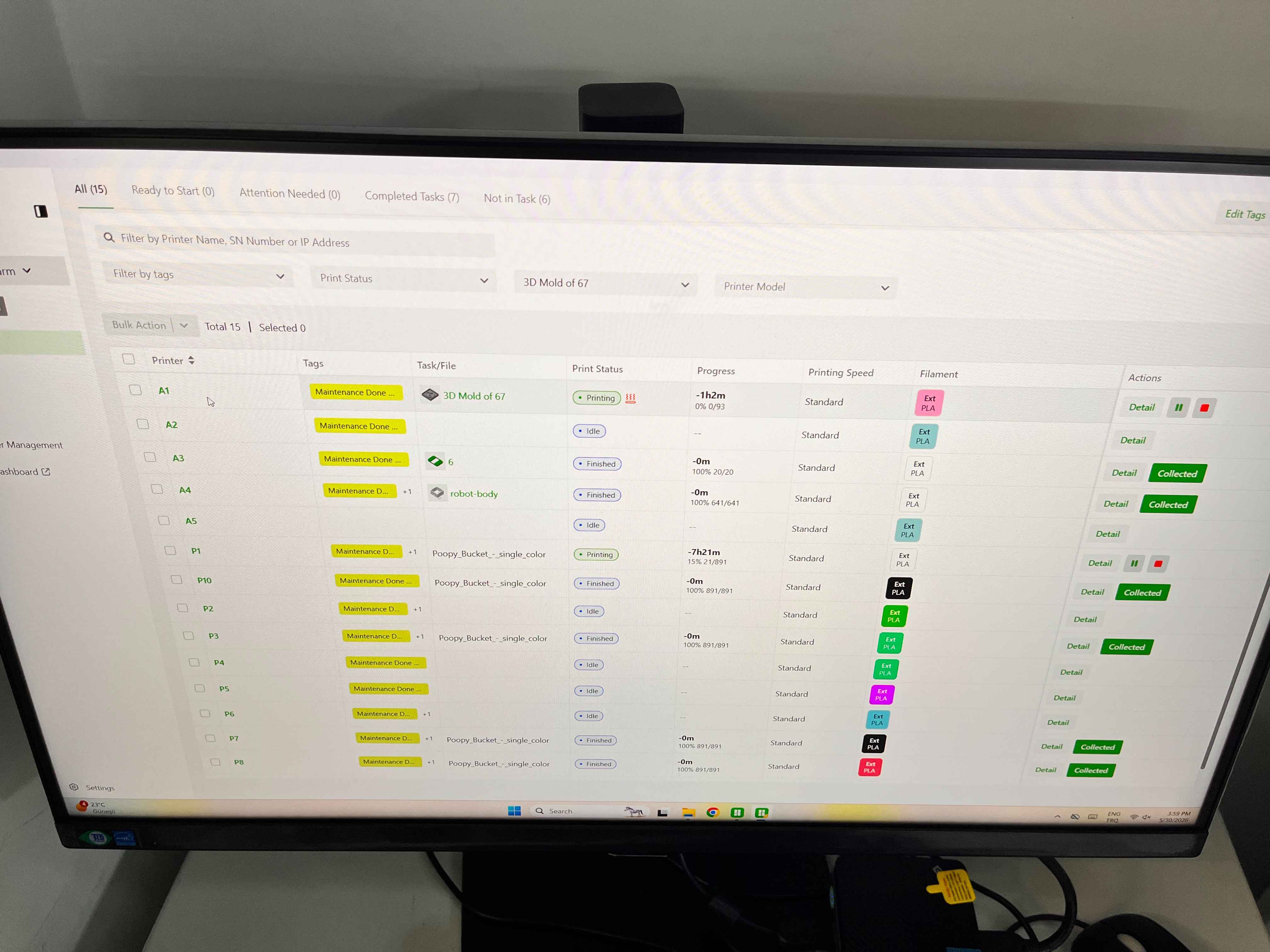
Here, send the 3D Mold that we made on Bambu Lab.
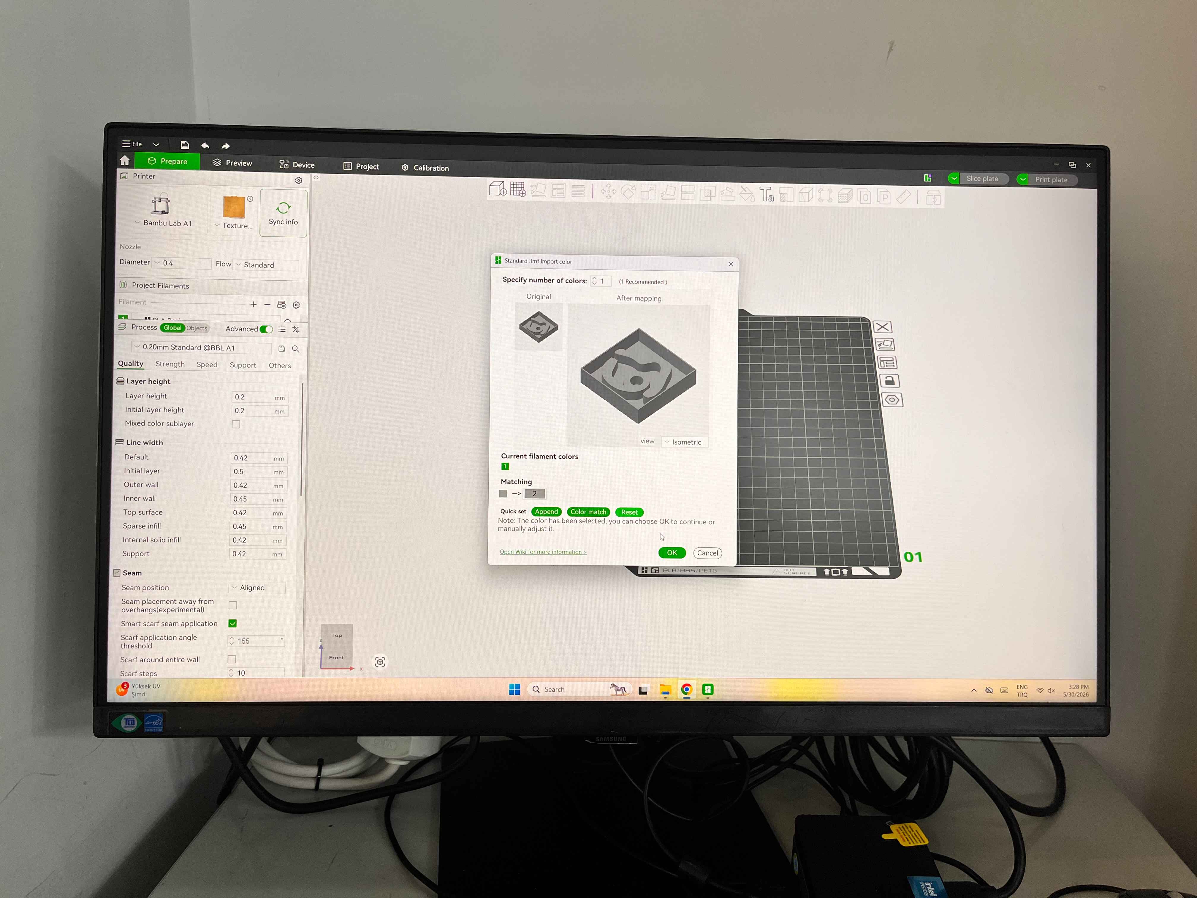
Click on Auto Orient.
Change Layer Height to 0.16mm.
Strength Settings
For Infill
- Use 20–25% Gyroid
If the mold is large or will be clamped:
- Use 30% Gyroid
There is no need for 100% infill.
For Infill Pattern
- Use Gyroid
Speed Settings
For molds, surface finish is more important than speed.
Reduce Outer Wall Speed to 50 mm/s and Inner Wall Speed to 100 mm/s.
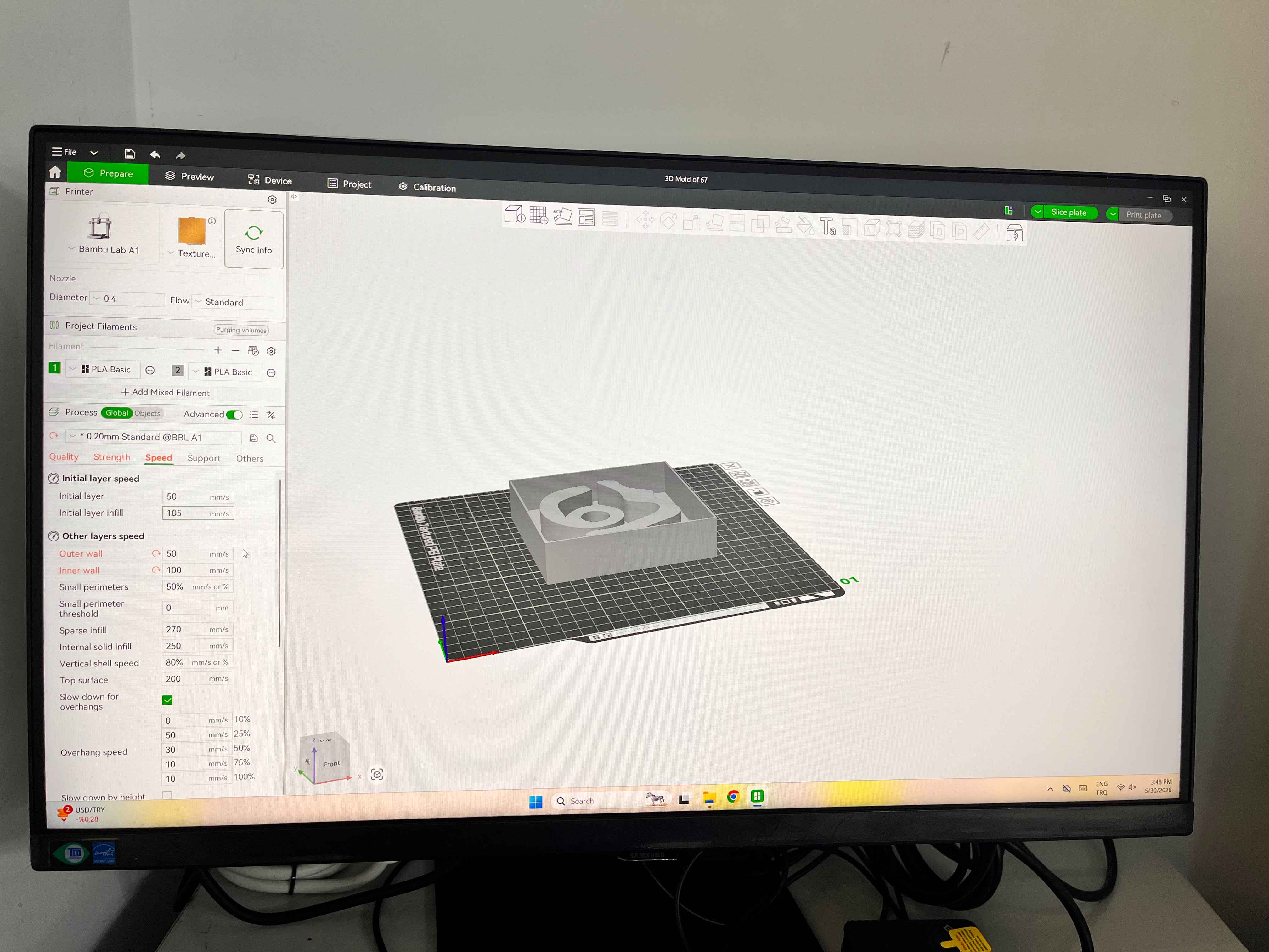
Also, if you have the option, try to Avoid Sport or Ludicrous mode.
Cutting
Reminder: Don’t enable any supports.
Resize you design into your liking.
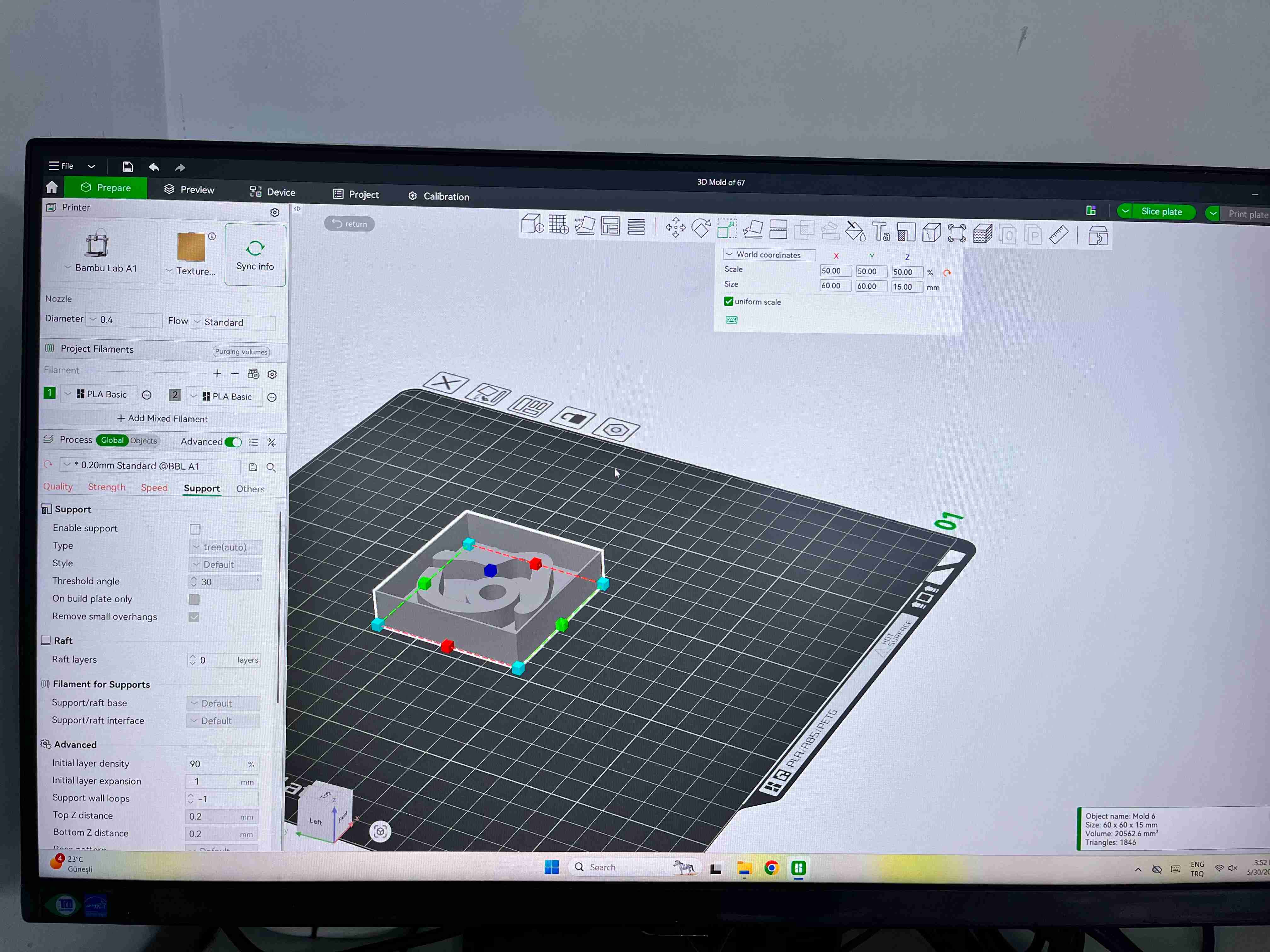
And, click to slice plate.
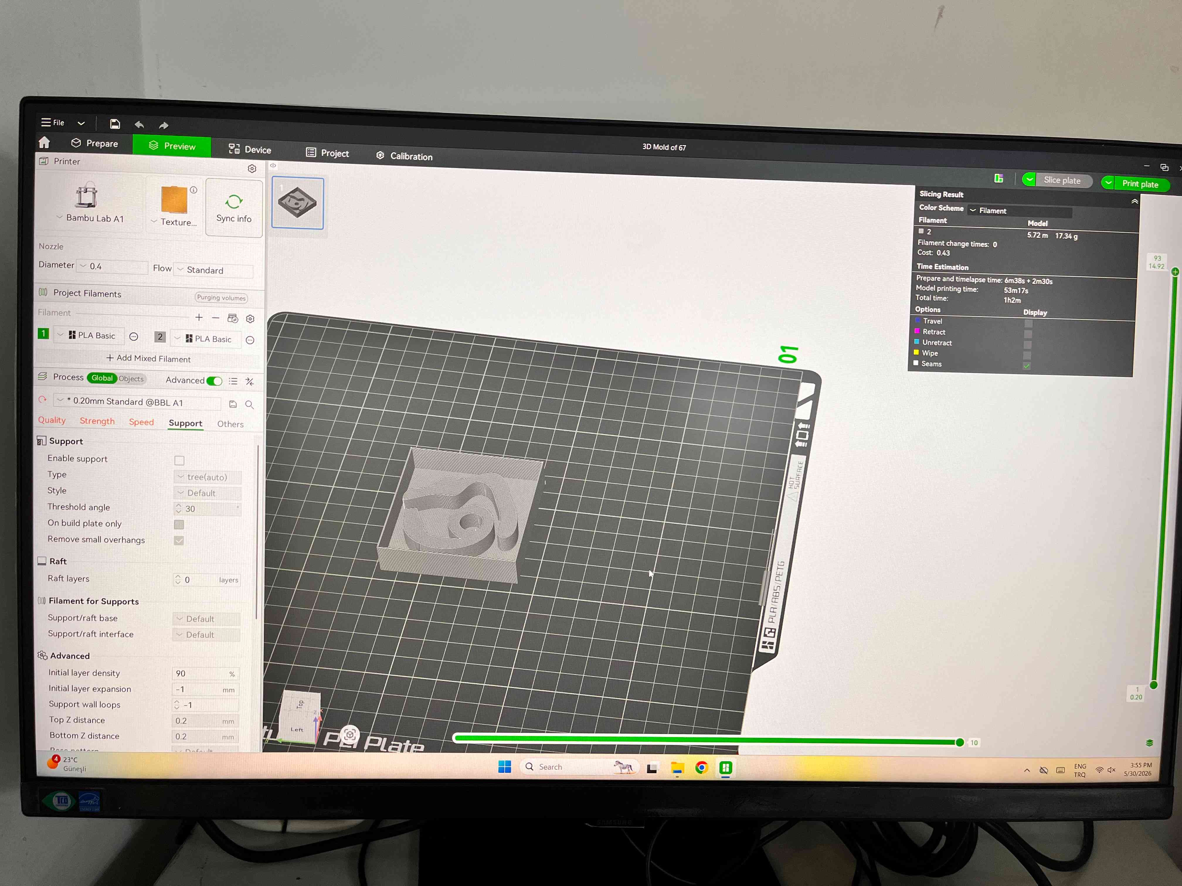
Click on Print Plate
Select the printer you want send the work.
Then Start your work.
After that, click on green arrow button on your printer, and it will start.
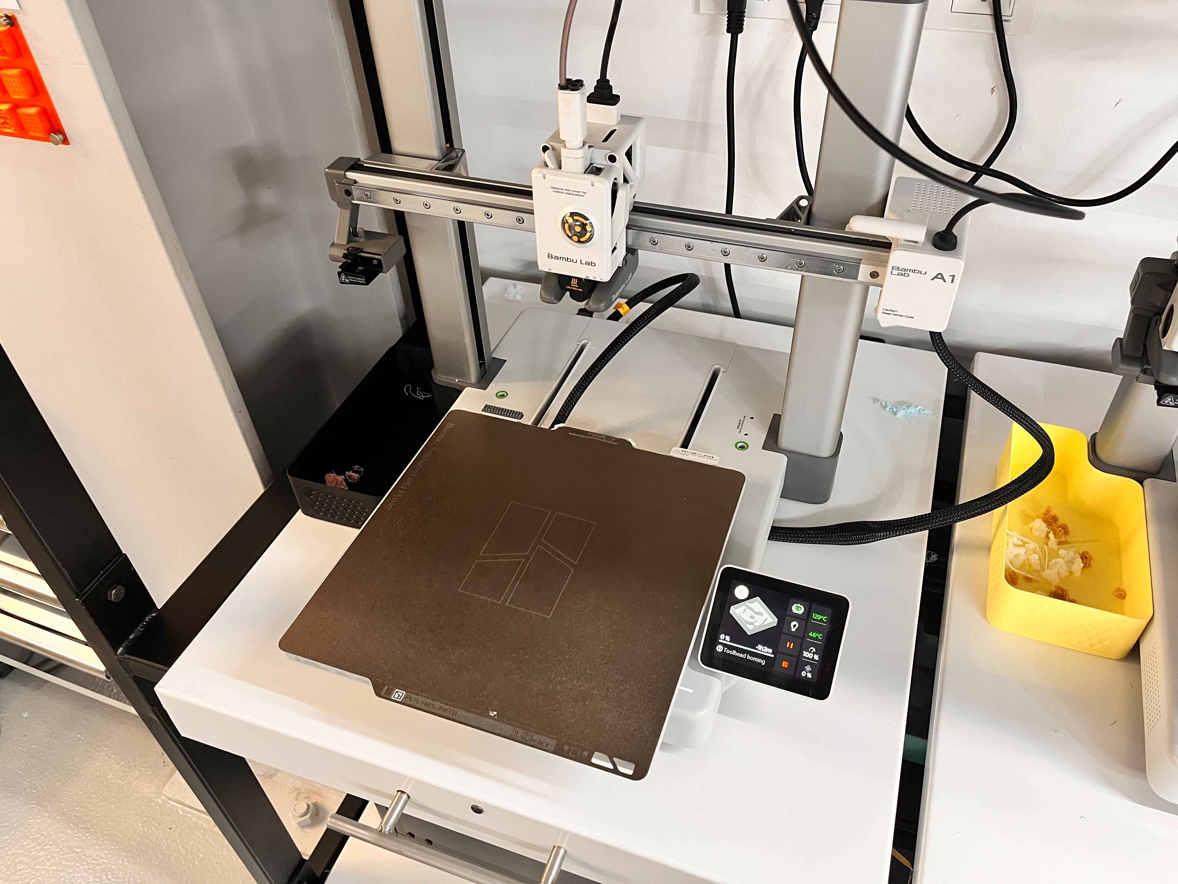
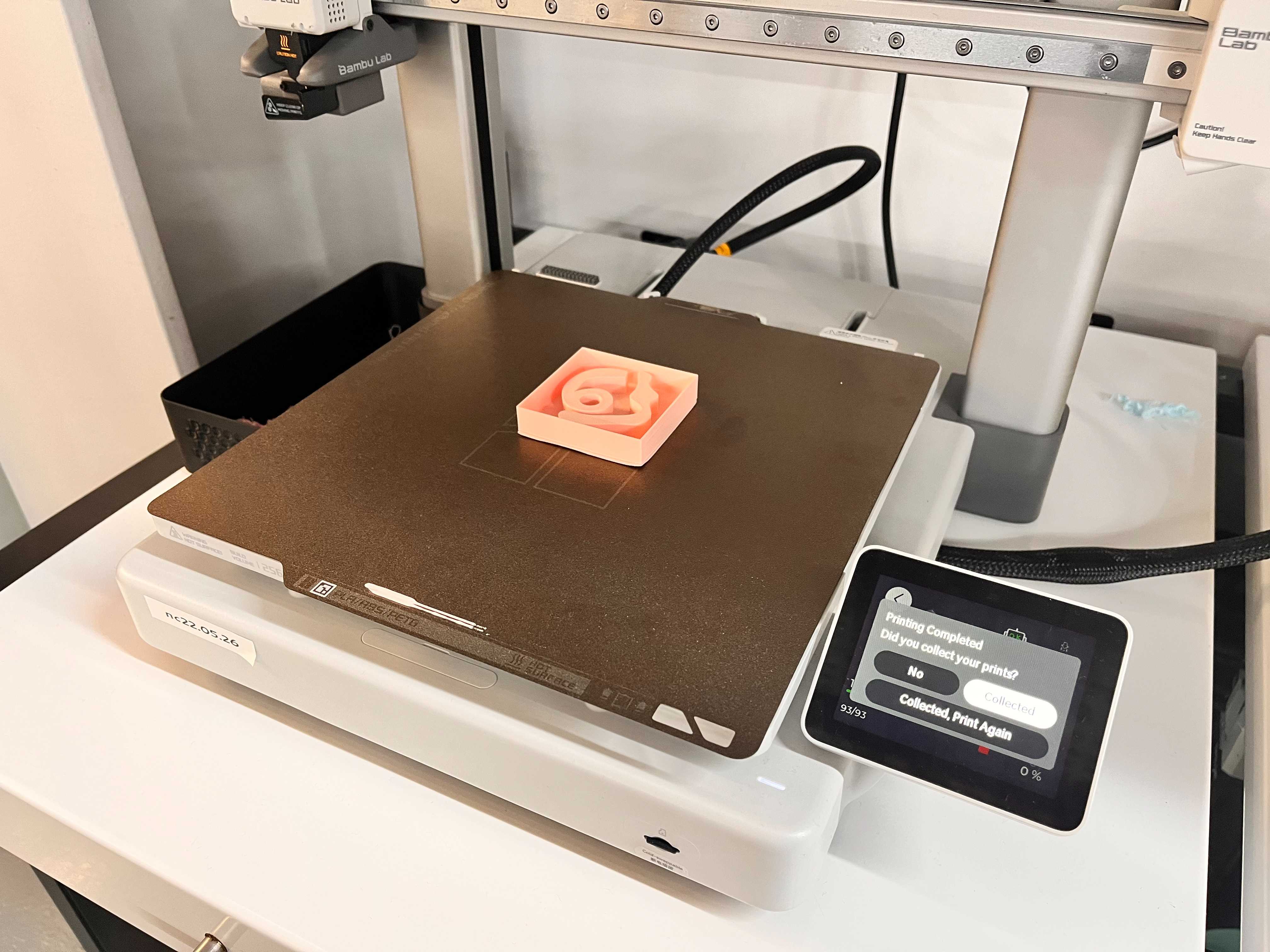
Here is a video of the printing process.
5 minutes after you are done, Collect your 3D print.
Creating the Mold and Cast with Wax
Preparing the Wax
First, I filled my 3D mold design with water and waited 5 to 10 minutes in order to check that there were no leaks.
There were no leaks.
After that, I poured that water into a cup to check how much amount of jax I was going to use.
I marked the water on the cup.
Later I mixed these two waxed as one part the yellow one and the other part dar blue one.
I stir and mix it well.
Preparing the Mold
I poured the wax into my 3D Mold.
After you pour it fully, take your mold and hit it into the table. This will leave the excess air bubbles inside the wax, which is important.
Preparing the Cast
Later, when your mold is solid, remove it and pour the same mixture again inside the mold.
I prepared a yellow wax solution.

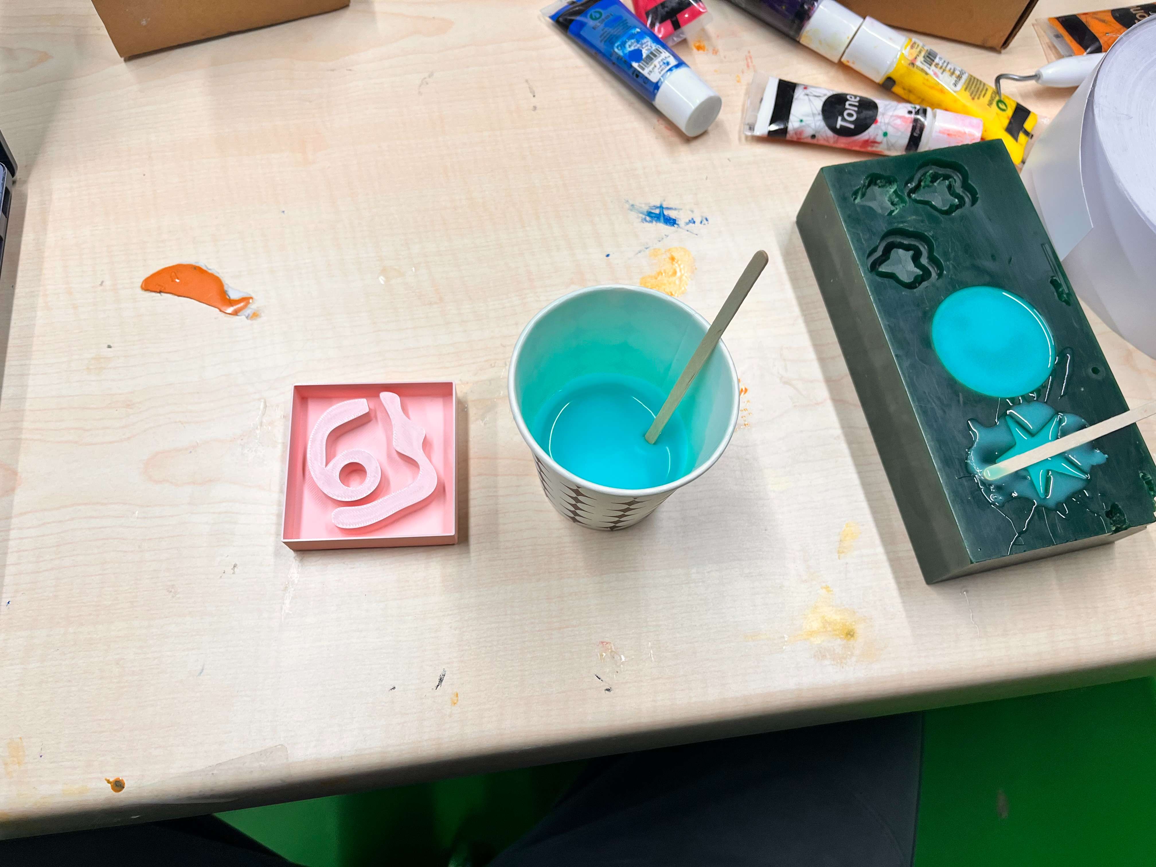
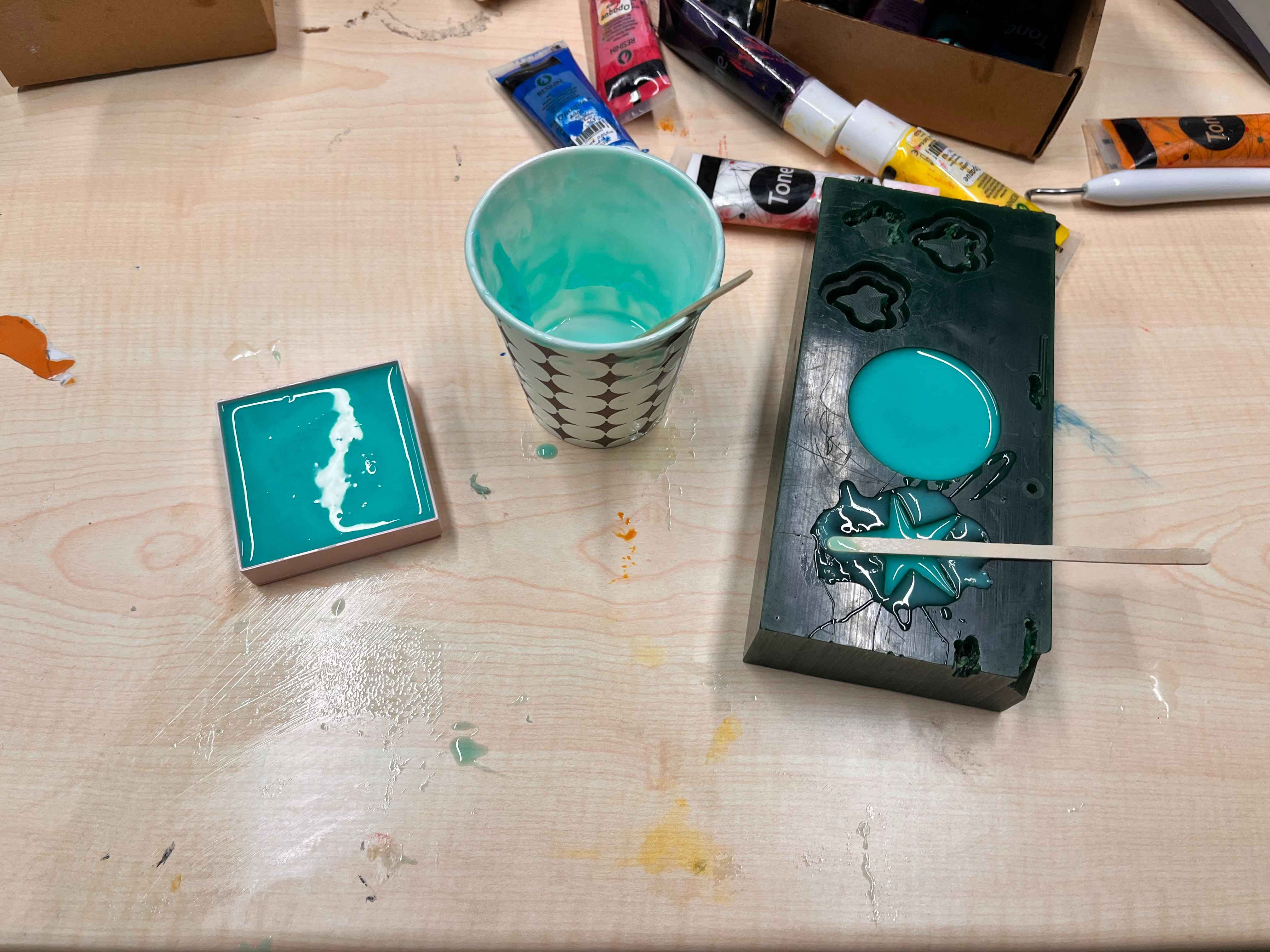
Then, brushed over my tray with yellow wax that I made because I wanted to give a yellow color.

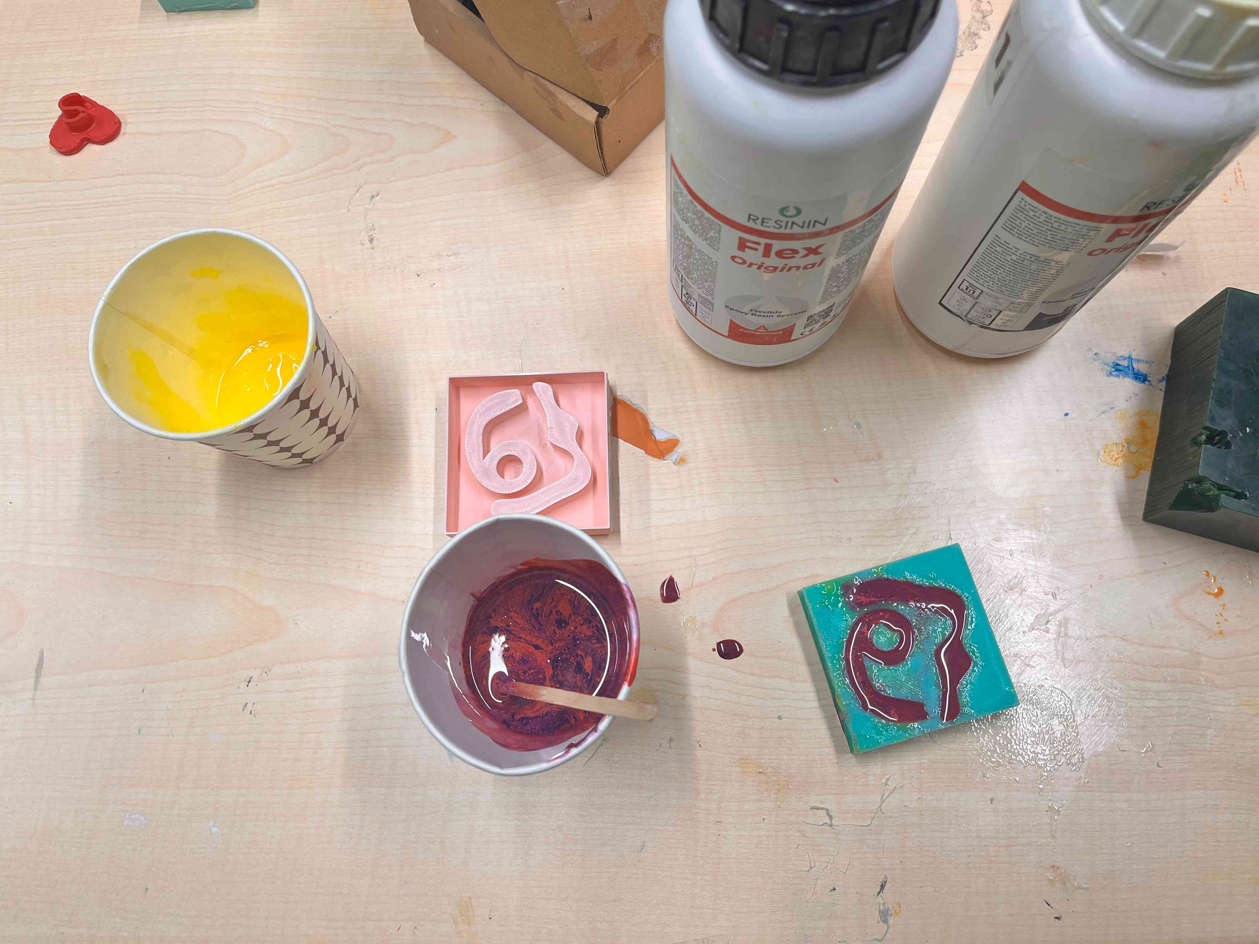
And, I poured in a cup one part A Resin and one part B Resin mixture.
I stirred these two.
I also added some pink and purple coloring dyes inside.
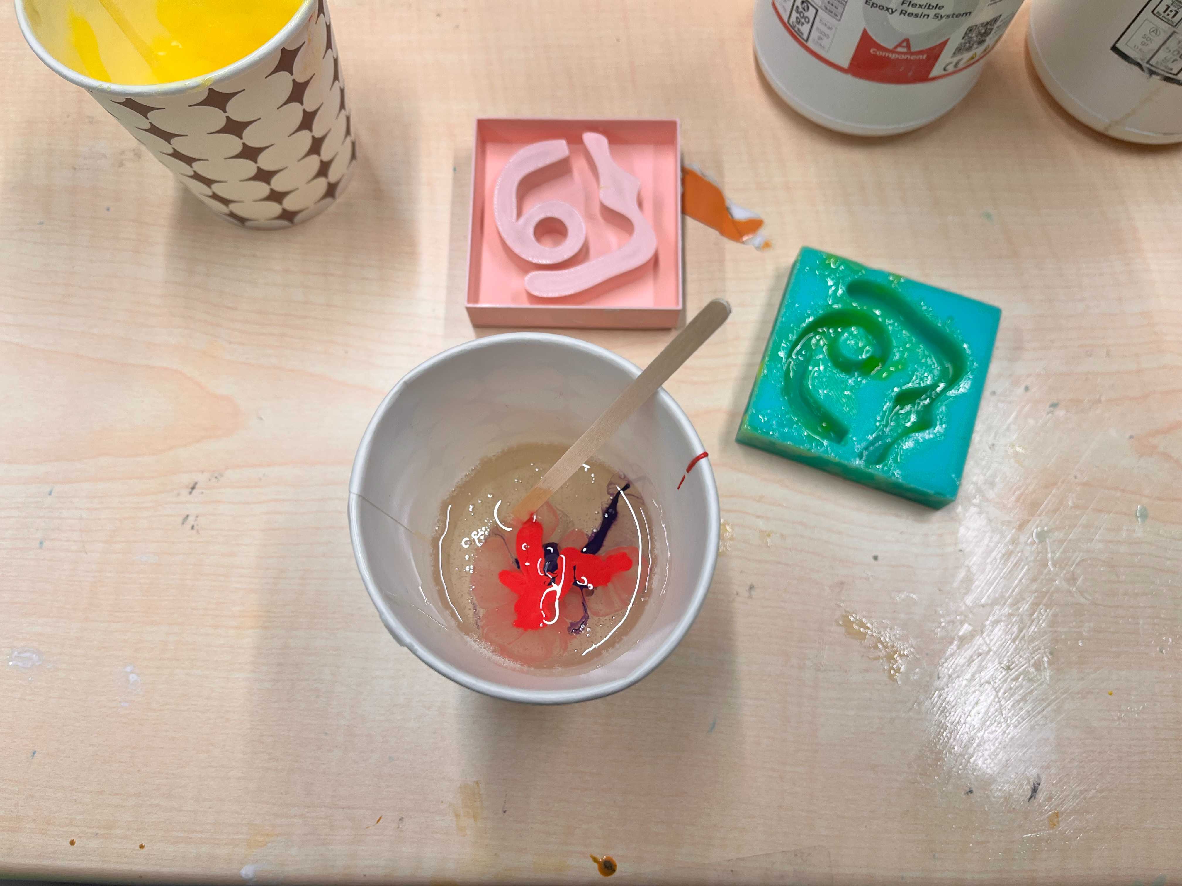
I stirred it a little again, but I was cautious on not getting them homogeneous.
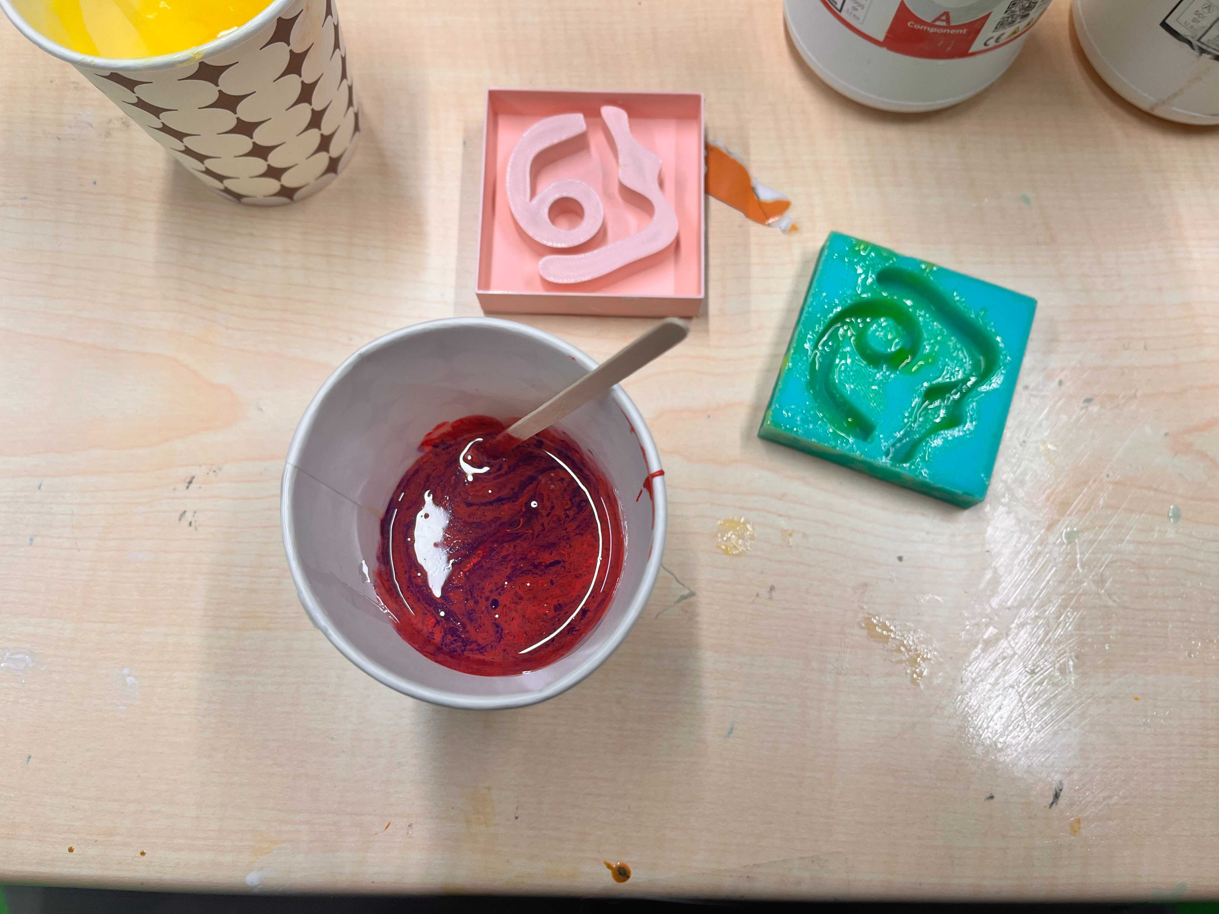
I then pour that inside my mold.
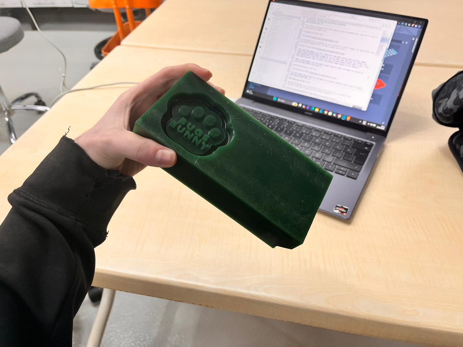
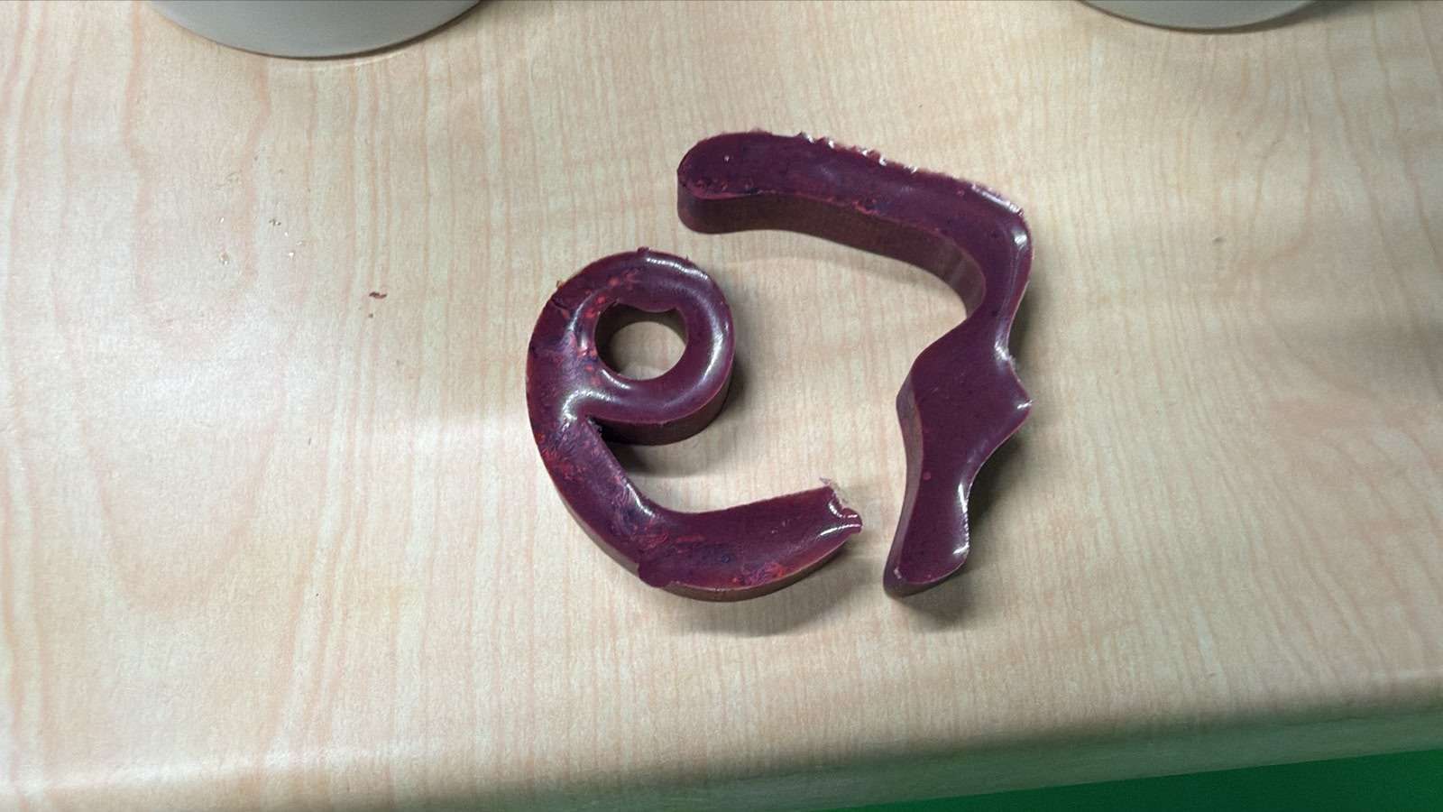
Finally, I removd the cast when its solid.
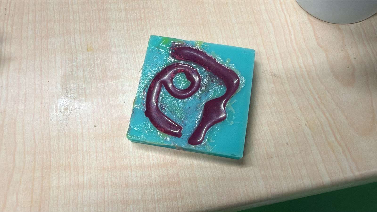
My final look of my cast was like the picture below.
Files
You can access to the files of this week from the link below.