Week 12 – Mechanical Design and Machine Design
Han Ferik
Weekly Assignments:
Check Out Our Machine Week
Mechanical Design (part 1 of 2)
Group assignment:
Design a machine that includes mechanism + actuation + automation + application
Build the mechanical parts and operate it manually
Document the group project
Individual assignment:
- Document your individual contribution
Machine Design (part 2 of 2)
Group assignment:
Actuate and automate your machine
Document the group project
Individual assignment:
- Document your individual contribution
Individual Contribution to Mechanical and Machine Design Week
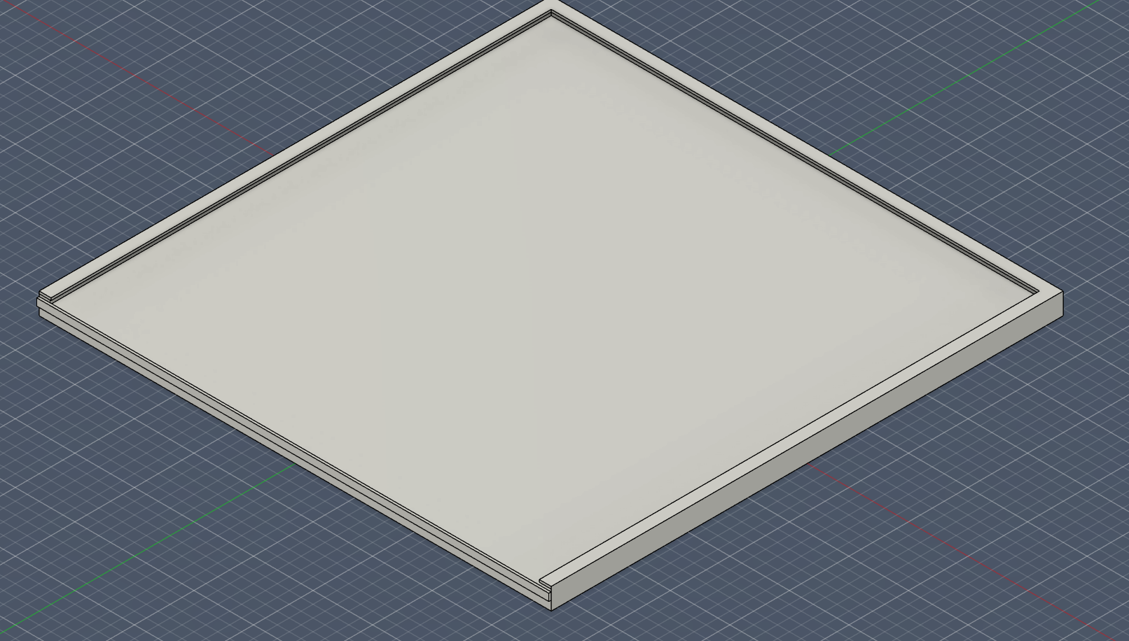
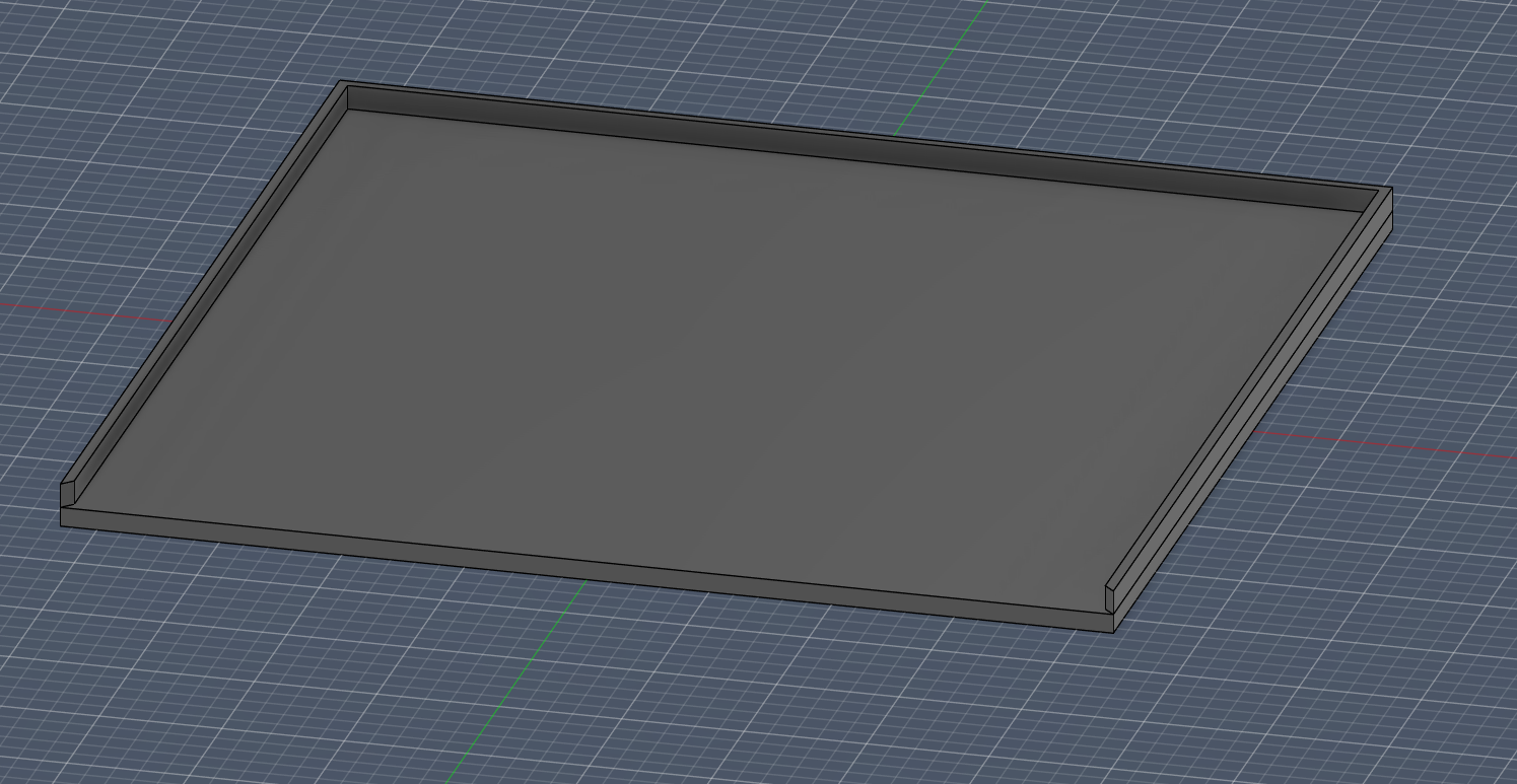
Paper Stop System
For our pen plotter, we were initially using tapes to put our paper into our machine for it to plot.
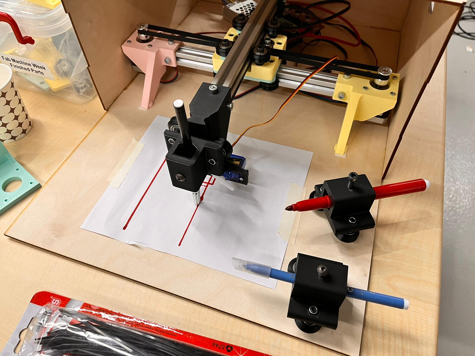
But, this was not quite a good choice both in terms of efficiency and the looks of our machine. So, I thought of creating a 3D printed plate that would hold our paper inside a frame. In order to do this, I sketched a design like this.

This design also has a few limitations into it. First of all, since our printer plate offers a maximum printing surface of 22cm x 22cm, that was the most enourmous one that I could draw and design. Also, there was a maximum range that our pen plotter could draw, which was 20cm x 20cm. Therefore, this actually fit perfectly.
But, one loss that we had was that we need to cut our papers in order to fit inside the paper stop system.
Fusion 360 3D Design
Parameters
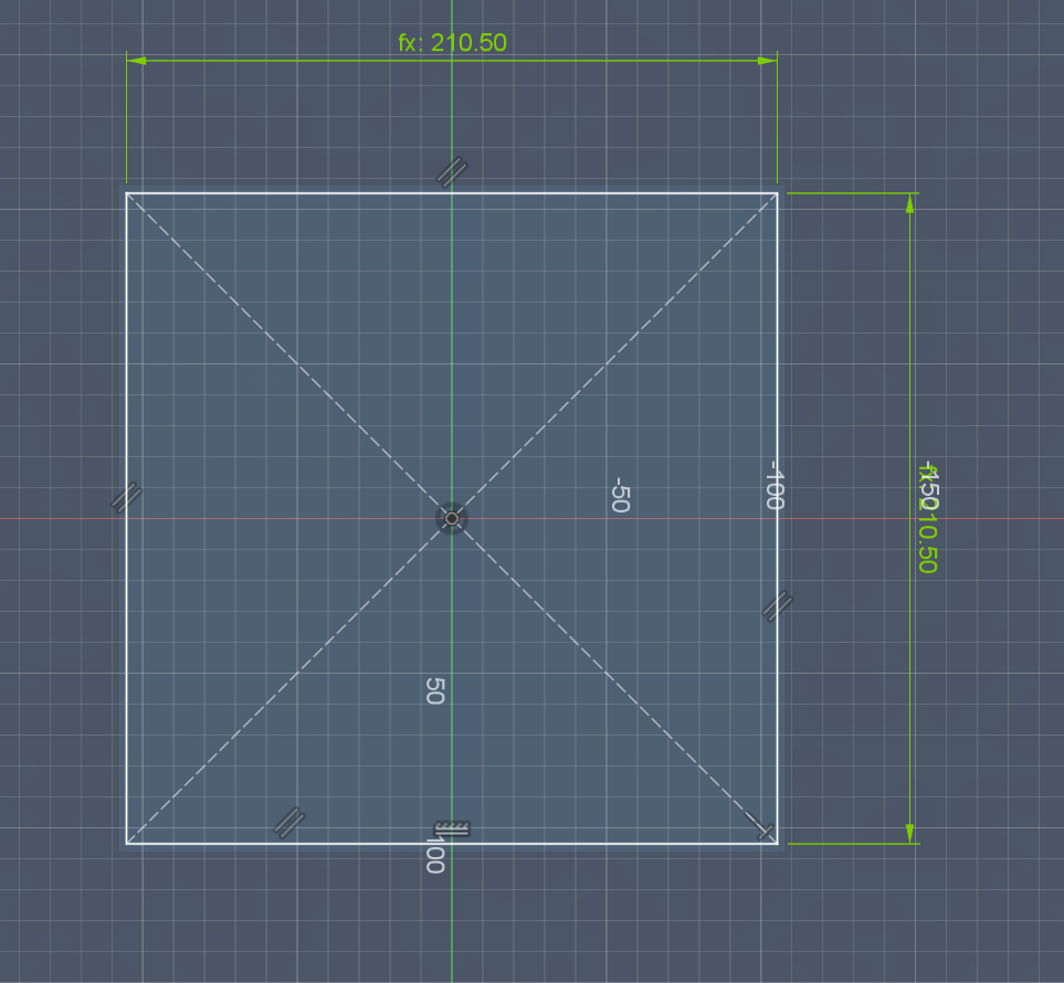
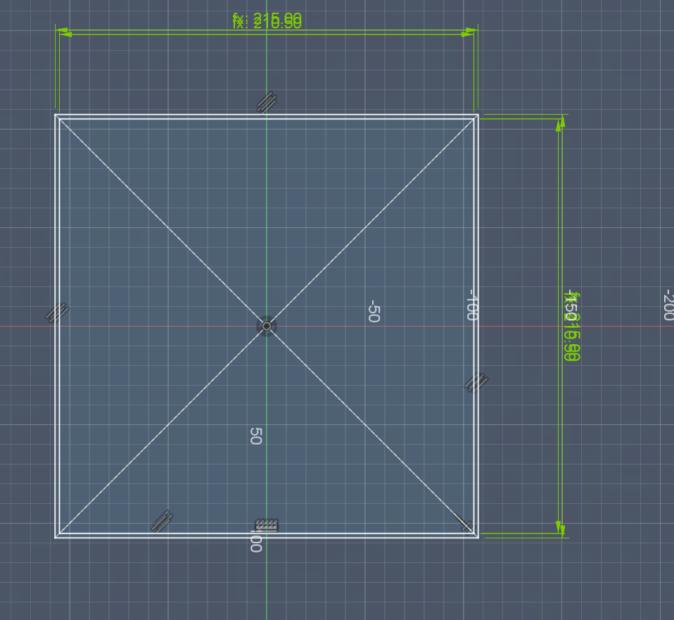
For its design, I wanted to make it parametric as I thought that the range of our machine could change in the future, so we could go for a decrease in range, so I could just easily change it through its parameters. So, I created the parameters below.
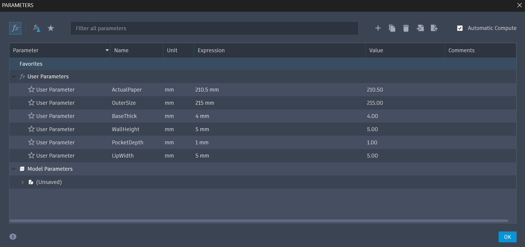
You can add these parameters through Modify and Change Parameters
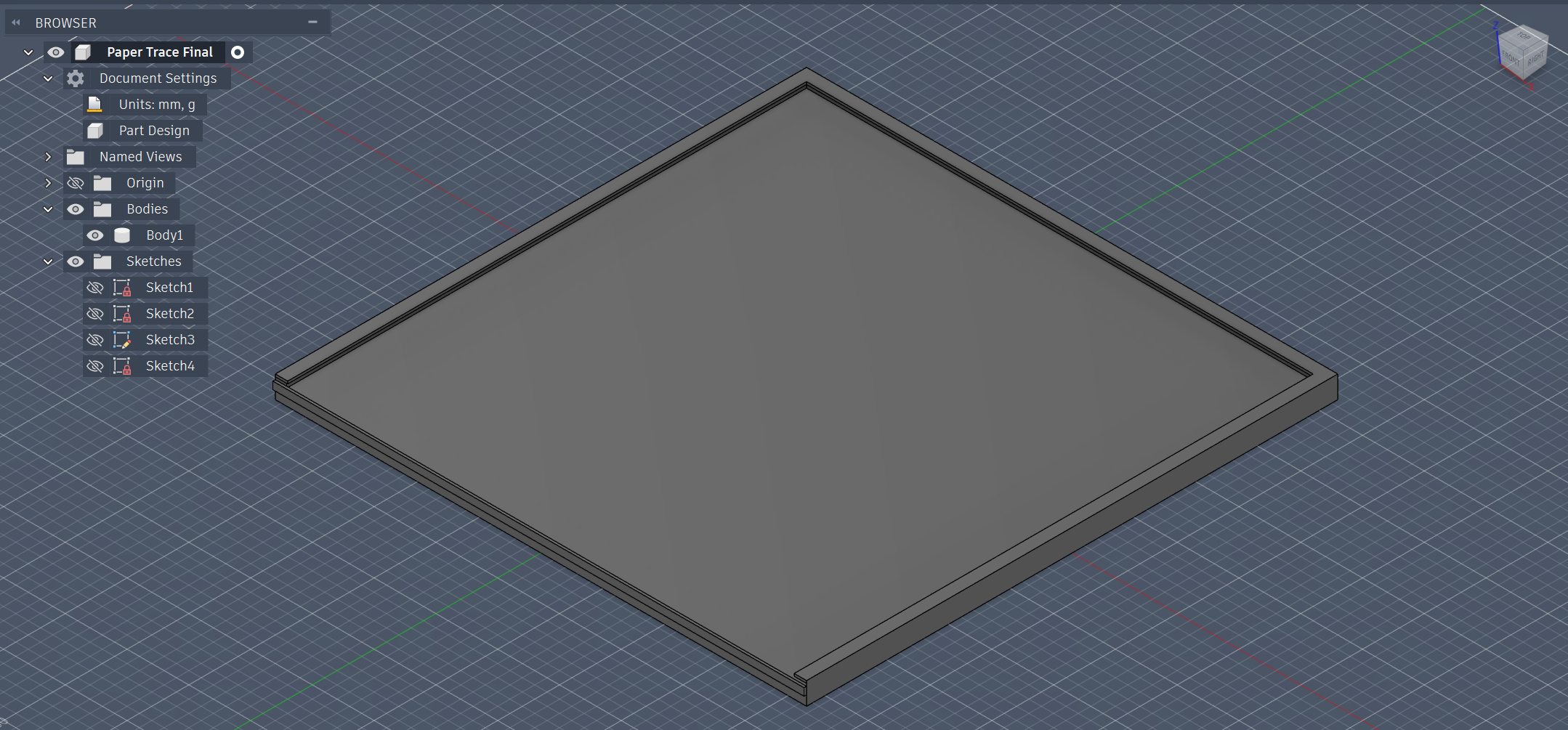
Main Base
After that for the main base,
Create Sketch on the XY Plane
Go to Create > Rectangle > Center Rectangle. Click the origin (center point) and pull it out.
Type OuterSize for both dimensions. Hit Enter
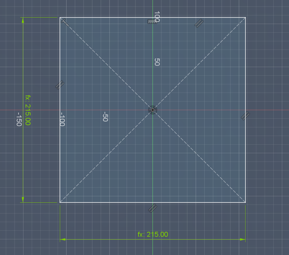
Finish Sketch
Extrude (Shortcut: E): Select the square and pull it up.
Type BaseThick
The Paper Pocket (The U-Channel)
Instead of cutting a hole in the middle, we are going to build the walls on top of the base in a “U” shape.
Create Sketch on the Top Face of your base.
Draw another Center Rectangle. Type ActualPaper for both dimensions.
- Draw a third Center Rectangle using OuterSize.
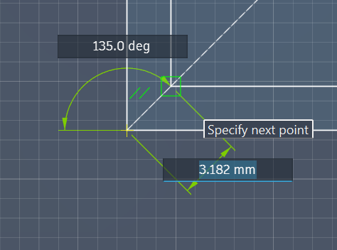
- Use the Line Tool (L). Draw two short lines at the “front” side of your plate. Connect the corner of the inner rectangle to the corner of the outer rectangle.
By doing this, you have “cut” the border. Fusion now sees the left wall, back wall, and right wall as separate shapes from the front wall.
- Finish Sketch.
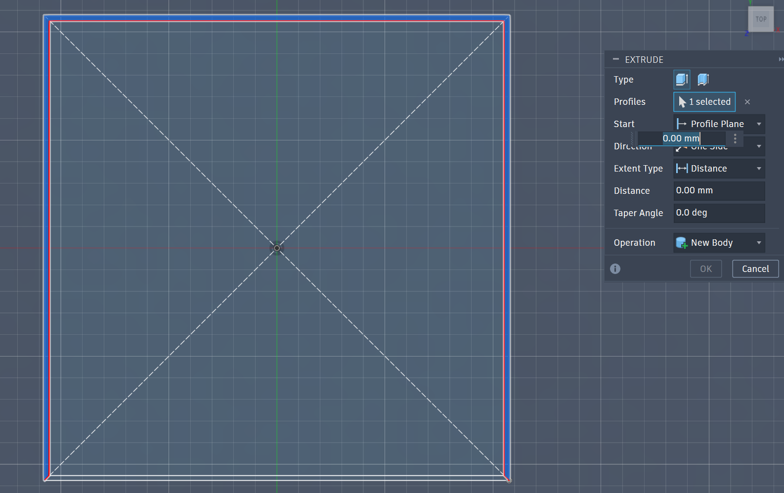
- Extrude (E): Now, you can click the Left, Back, and Right segments of the border. Do not click the front segment.
The Frame
Step 1: Sketch The Frame
Create Sketch on the Top Face of your three existing walls.
Use the Offset Tool (Shortcut: O):
Click the inner edges of your three walls.
Pull the offset inward (toward the center of the paper).
Type -lip_width (the negative sign ensures it moves inward).
- Close the Profile: If the offset doesn’t automatically create a closed shape, use the Line Tool (L) to connect the ends of your offset lines to the outer corners of the walls.
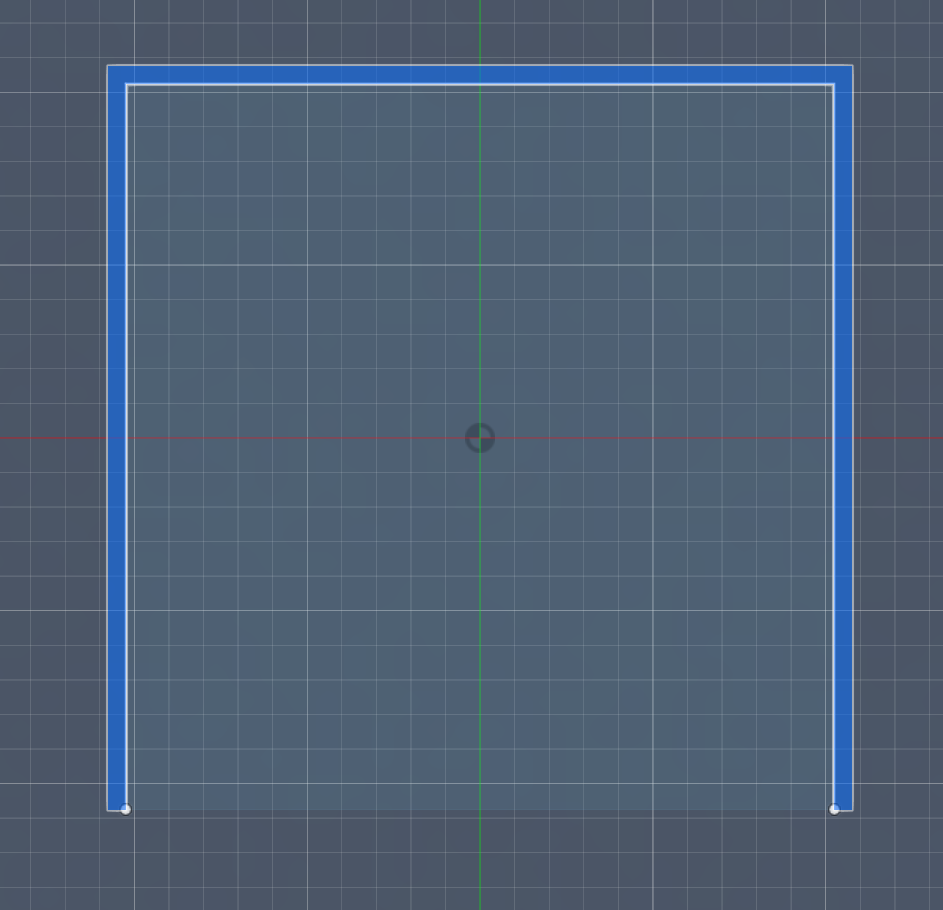
- Finish Sketch.
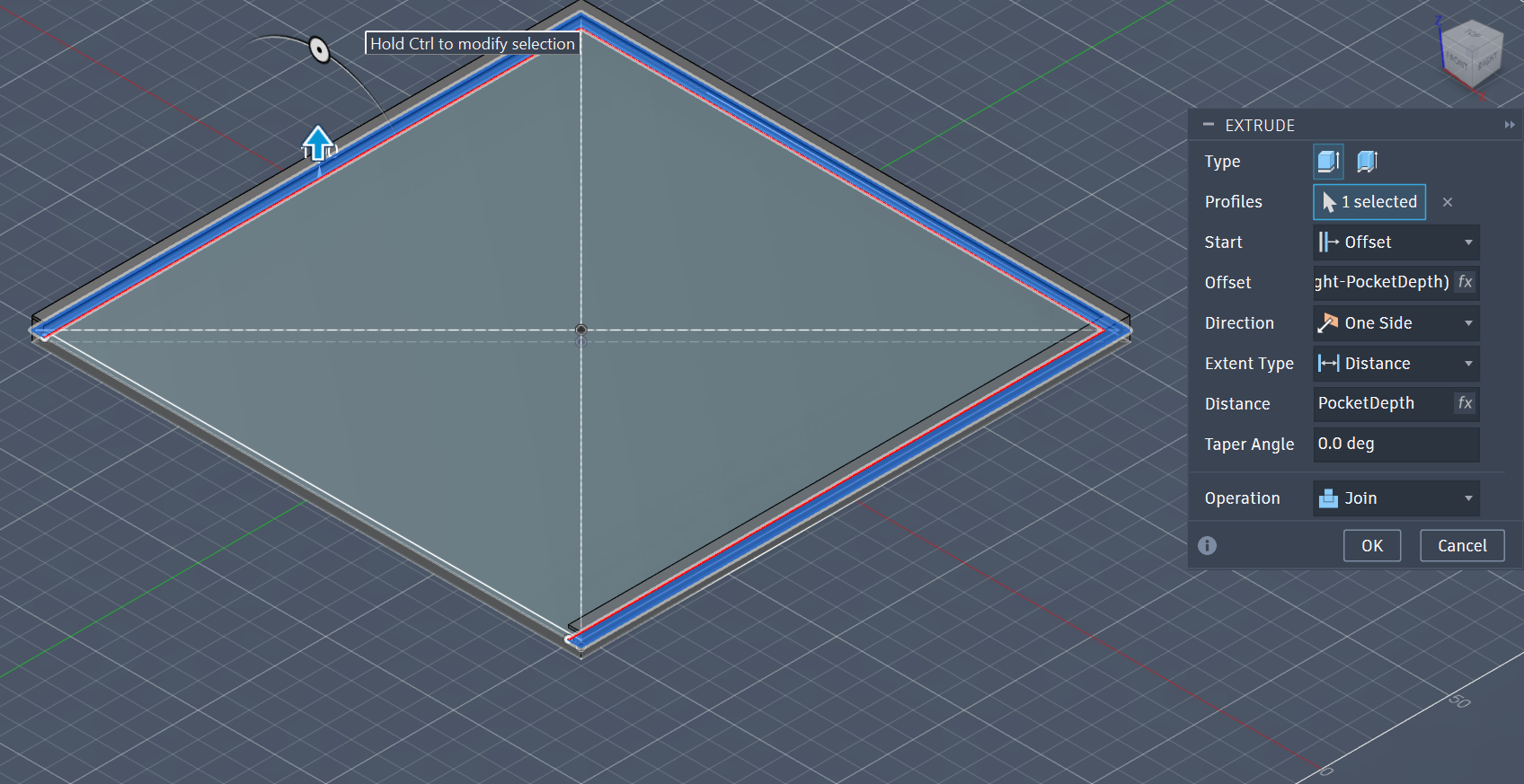
Step 2: Extrude the FrameExtrude (Shortcut: E):
Select the new “frame” profile you just drew (the three-sided border that overhangs the paper area).
Start: Offset
Offset: Type -(WallHeight - PocketDepth).
Distance: PocketDepth
Operation: Set to Join.
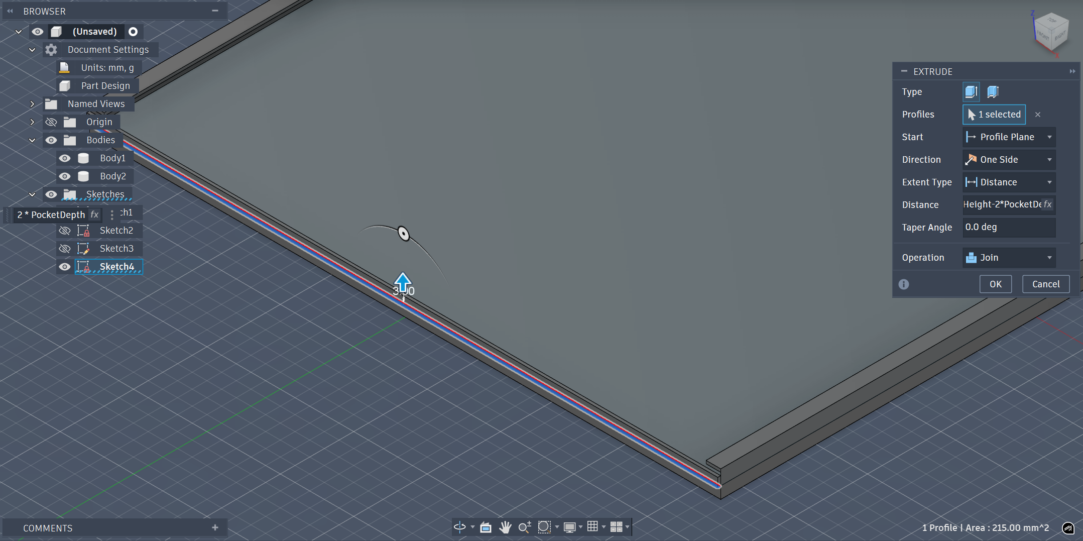
The Clipper
Now that you have a frame on three sides, you just need to close the entrance with the clipper so the paper is locked in from all four directions.
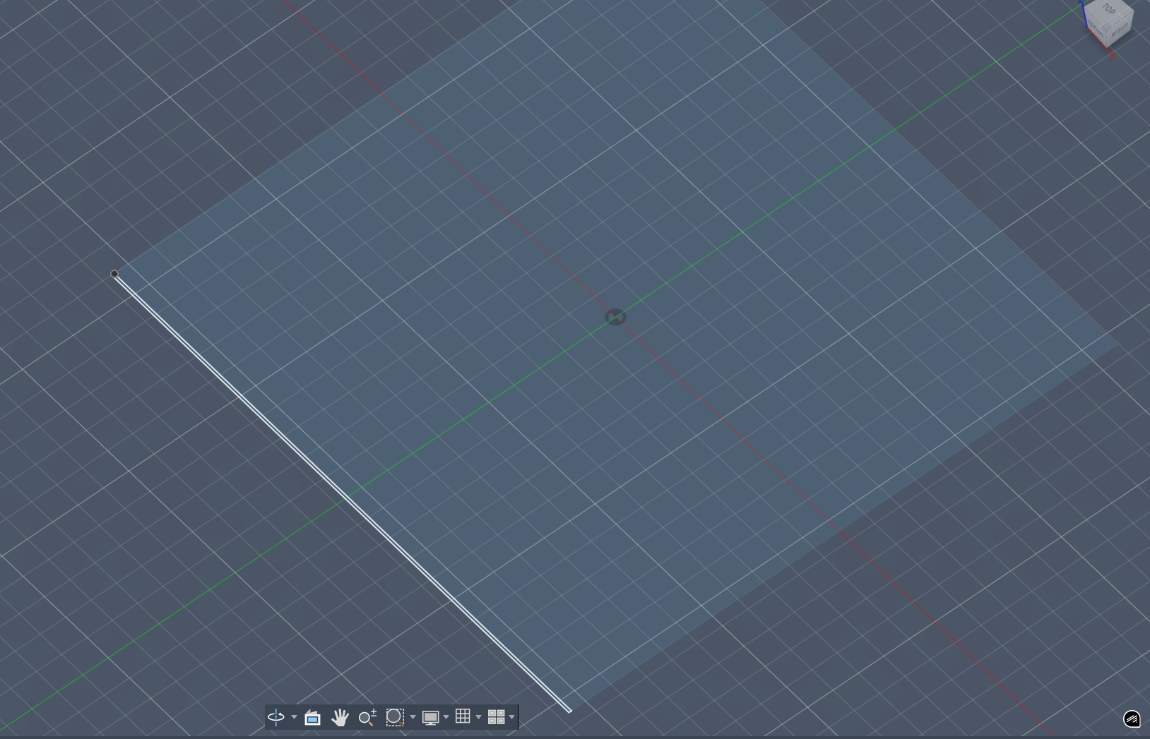
Create Sketch on the top face of the front ends of your side walls.
Draw a Rectangle that bridges the gap at the front.
Extrude (E):
Distance: WallHeight - 2*PocketDepth
Operation: Set to Join.
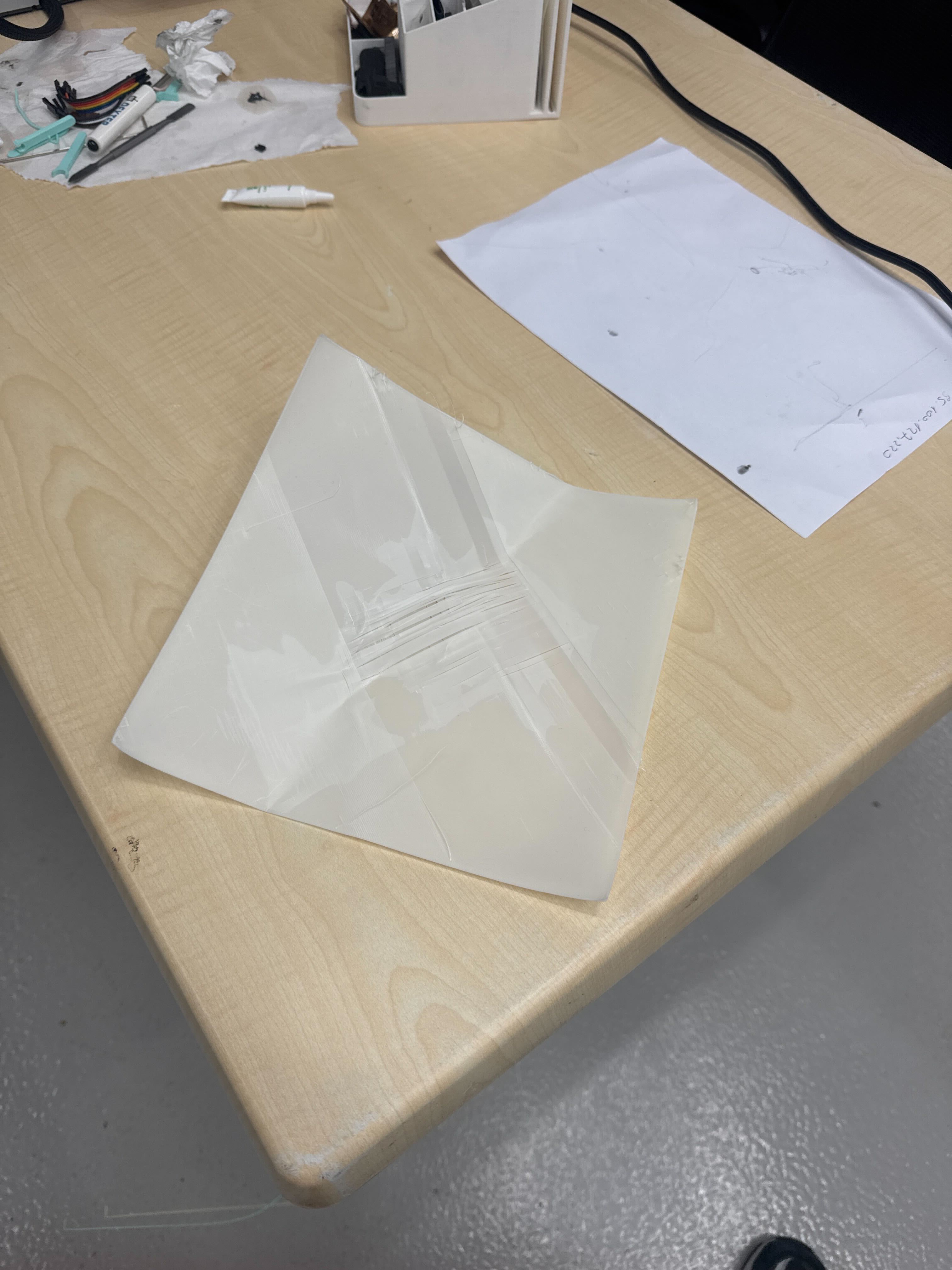
Final Design
Printing The Design
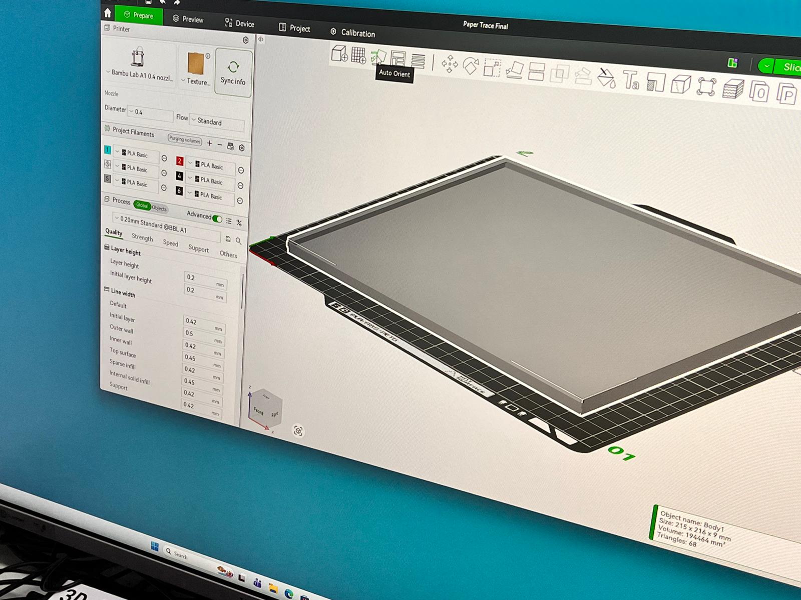
We use BambuLab as for our 3D Machine. So, open your Bambu Lab.
Open up your 3D file in the program.
When it opens, first click autoorient for the object to set on the ground.
Enable the supports and select support critical regions only.
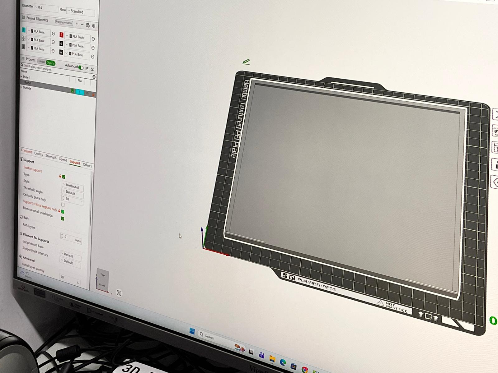
After that, slice the plate, and export the sliced file.
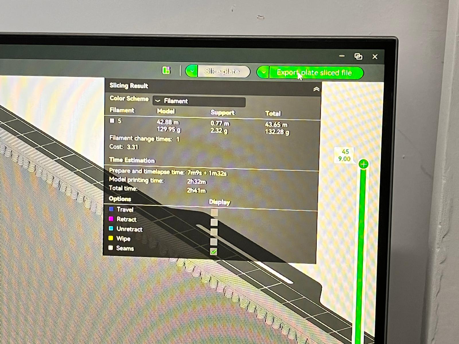
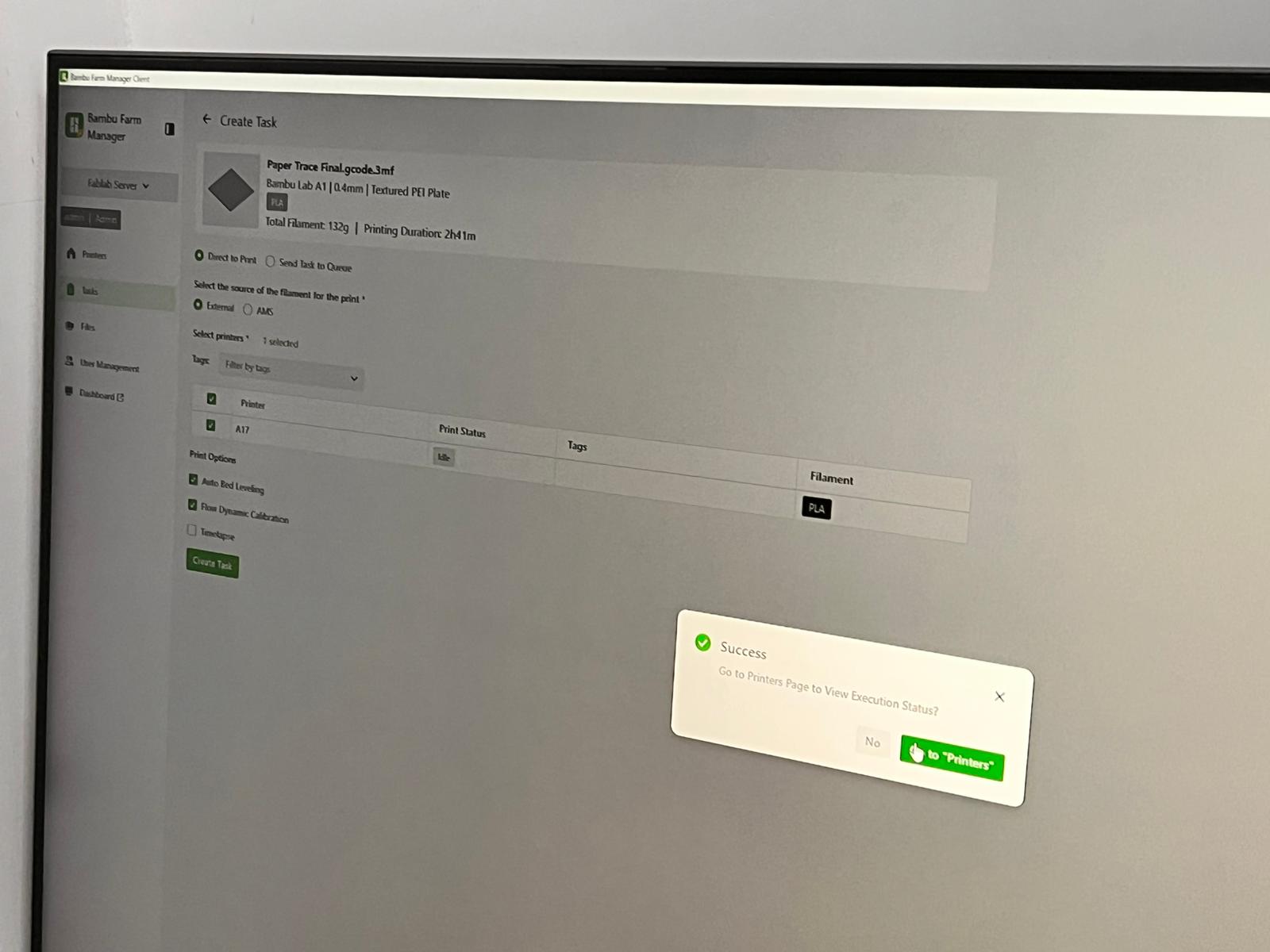
Finally send it to your printers and print the 3D design.
At your printing phase,
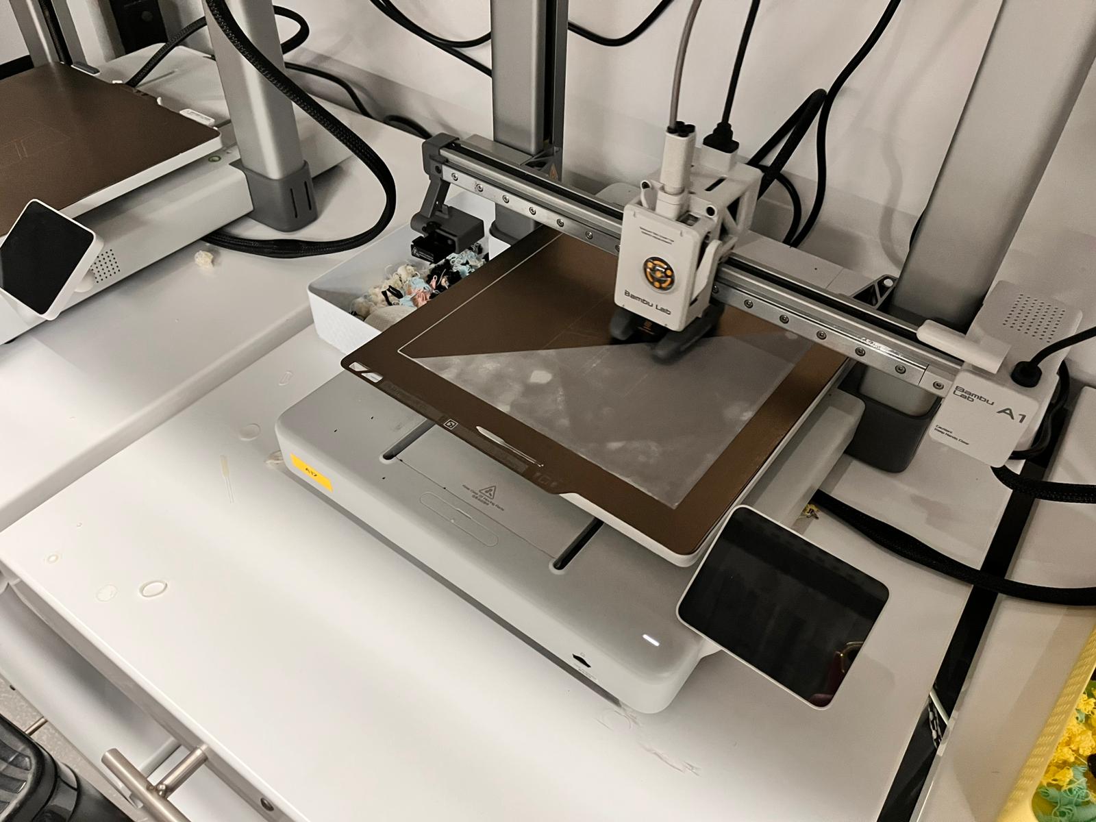
Make sure to print it in a low speed printing form because if its fast than it might fail with the supports and your whole structure might fail up.
Files
You can access to the files of this week from the link below.