Week 04 – Embedded Programming
Han Ferik
Weekly Assignments:
Check Out Our Group Assignment
Group assignment:
Demonstrate and compare the toolchains and development workflows for available embedded architectures
Document your work to the group work page and reflect on your individual page what you learned
Individual assignment:
Browse through the datasheet for a microcontroller
Write and test a program for an embedded system using a microcontroller to interact (with local input &/or output devices) and communicate (with remote wired or wireless connections)
Bill of Materials
Core Board
Raspberry Pi Pico W
Micro-USB cable
For Experiments
Breadboard
Jumper wires (Male-Male, Male-Female)
LEDs (5mm)
Servo motor (SG90 recommended)
HC-SR04 Ultrasonic sensor
L298N Motor driver module
DC motor
External 5–9V battery (for motor driver)
Introduction to the Raspberry Pi Pico W
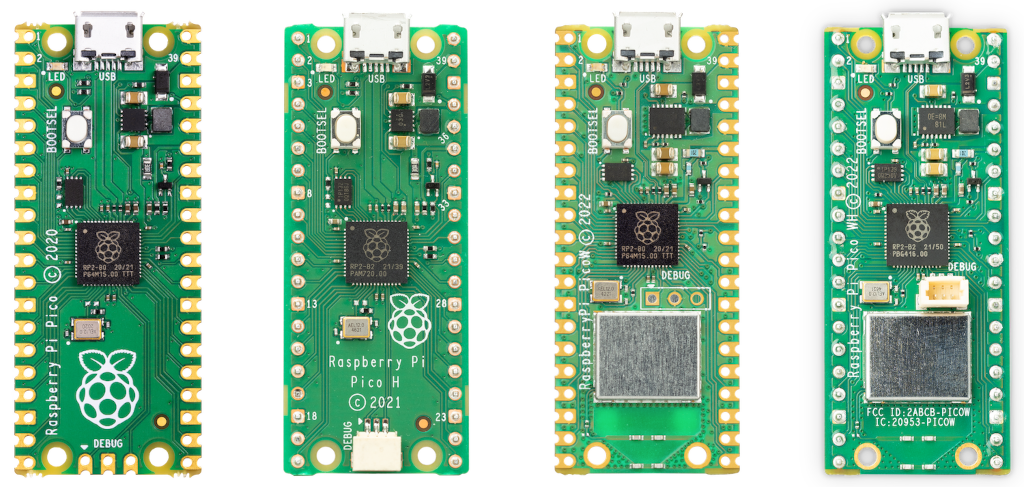
Source: Raspberry Pi Website
The RP2040 Microcontroller:
The Pico W is built around the:
RP2040 microcontroller (designed by Raspberry Pi)
Core Processor Specifications
| Feature | Description |
|---|---|
| Dual-Core | 2 × ARM Cortex-M0+ |
| Clock Speed | Up to 133 MHz |
| RAM | 264 KB SRAM |
| Flash | 2 MB external flash |
| Programmable I/O | PIO state machines (very powerful feature!) |
| ADC | 12-bit ADC |
| PWM | 16 PWM channels |
Advanced Feature: PIO (Programmable IO) This is what makes RP2040 special. It allows you to create custom hardware protocols in software.
You can:
Create custom communication protocols
Drive displays
Generate precise signals
Model Comparison: Pico vs. Pico W
| Feature | Pico | Pico W |
|---|---|---|
| RP2040 Chip | ✅ | ✅ |
| Wi-Fi | ❌ | ✅ |
| Bluetooth | ❌ | ✅ (BLE) |
| Wireless Chip | ❌ | Infineon CYW43439 |
The Pico W includes:
Infineon CYW43439
Supports:
2.4 GHz WiFi
Bluetooth Low Energy (BLE)
It communicates internally with RP2040 using SPI.
Technical Specifications
| Parameter | Value |
|---|---|
| CPU | Dual ARM Cortex-M0+ |
| Clock | 133 MHz |
| RAM | 264 KB |
| Flash | 2 MB |
| GPIO | 26 usable |
| ADC | 3 external channels |
| PWM | 16 channels |
| Logic Level | 3.3V |
| Wireless | 802.11n WiFi + BLE |
Hardware Architecture
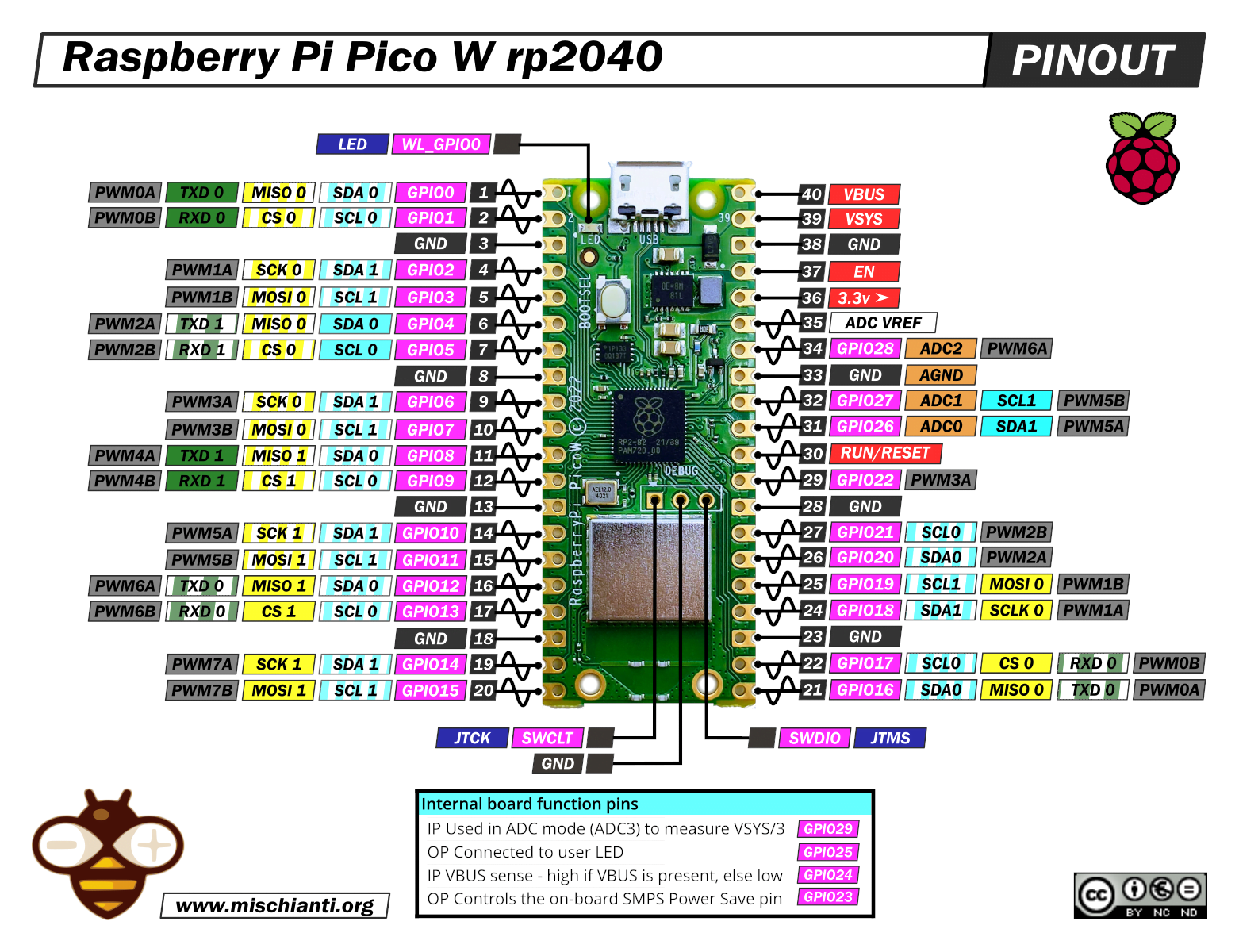
Source: www.mischianti.org
Pinout Overview
The Pico W has:
40 pins total
26 GPIO pins
3 ADC pins
Power pins
Ground pins
Power Pins
| Pin | Function |
|---|---|
| VBUS | 5V from USB |
| VSYS | Main power input (1.8–5.5V) |
| 3V3(OUT) | 3.3V regulated output |
| GND | Ground |
Safety & Power (VERY IMPORTANT)
3.3V LOGIC ONLY
The Pico W GPIO pins:
MAX voltage: 3.3V
If you connect 5V → you can permanently damage the board
Power Paths Explained
USB plugged → 5V on VBUS
VSYS feeds onboard regulator
Regulator outputs stable 3.3V
Never power motors directly from Pico.
GPIO Capabilities
Each GPIO can:
Digital input
Digital output
PWM
I2C
SPI
UART
ADC pins:
GP26
GP27
GP28
Initial Setup & Firmware
Flashing MicroPython (BOOTSEL Method)
- Hold BOOTSEL button
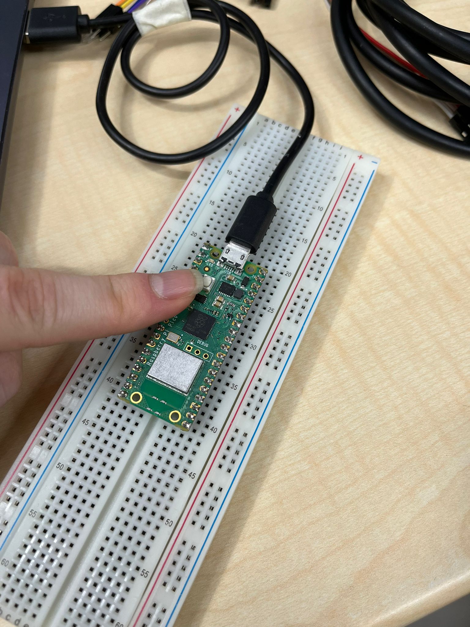
Plug USB into computer
Release BOOTSEL
A drive appears named:
RPI-RP2
- Drag MicroPython UF2 file into it (Access MicroPython UF2 From Here)
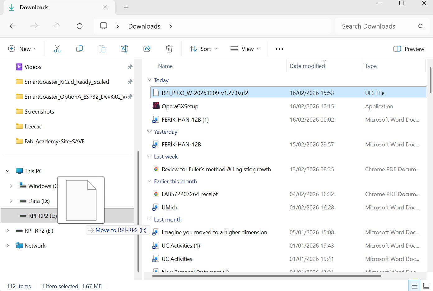
- Board reboots automatically
You’re done.
Setup Thonny IDE
Install Thonny (Download Thonny From Here)
Open Thonny
Go to:
Tools → Options → Interpreter
- Select:
MicroPython (Raspberry Pi Pico)
Choose correct COM port
Click OK
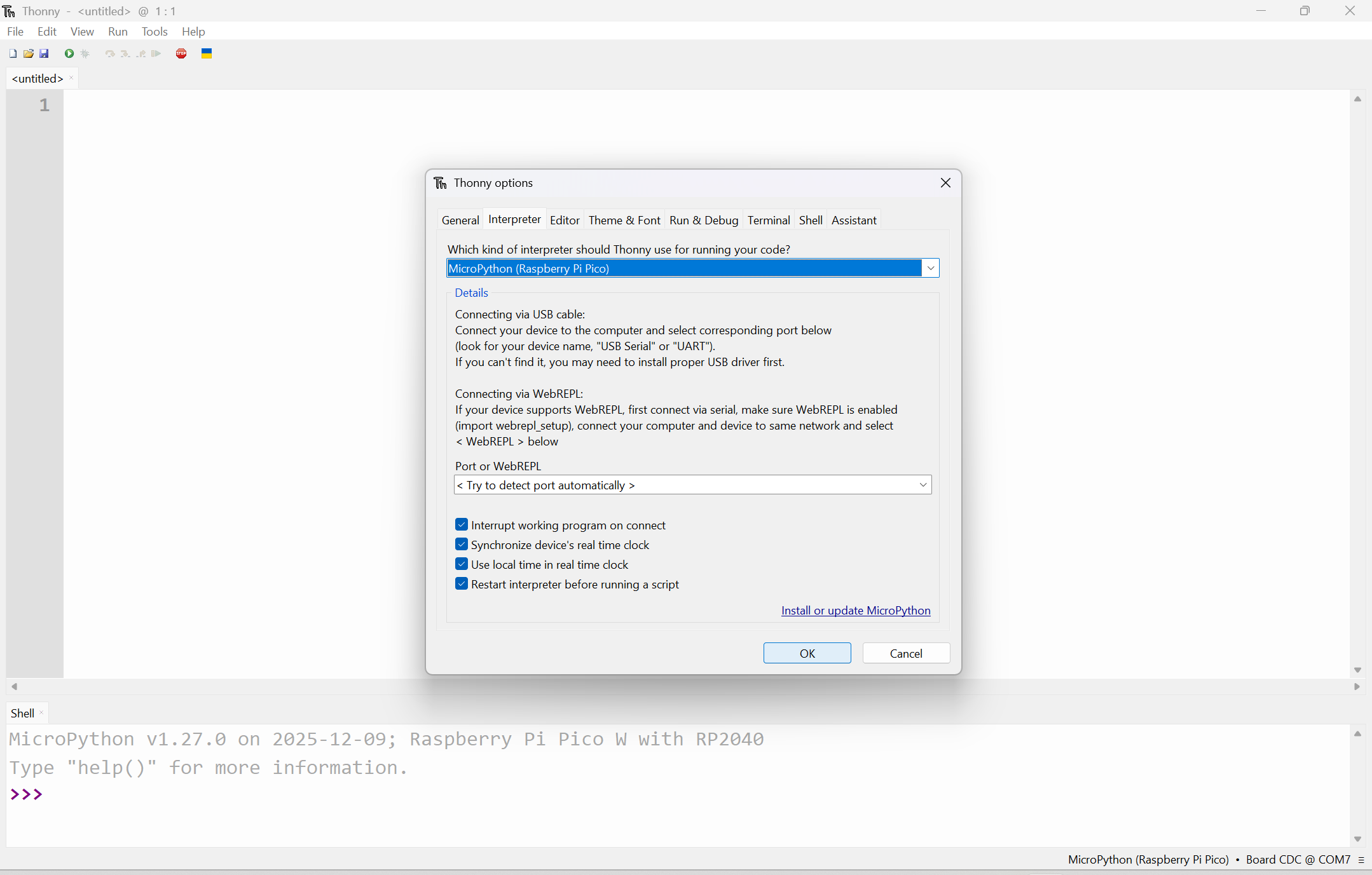
You should now see:
>>>
REPL prompt.
Experimenting with Our Microcontroller
Blink Onboard LED
The Pico W onboard LED is connected differently than standard Pico.
On Pico W, LED is controlled through wireless chip.
PHASE 1 – Blink Code
import network
import time
from machine import Pin

led = Pin("LED", Pin.OUT)

while True:
    led.toggle()
    time.sleep(0.5)
Run it.
If LED blinks → your environment is correct.
Pico W Blink Video

Blink External Led
Wiring
| Component | Connect To |
|---|---|
| LED long leg | GP15 |
| LED short leg | 220Ω resistor |
| Resistor other side | GND |
PHASE 2 – External LED Blink Code
from machine import Pin
import time

led = Pin(15, Pin.OUT)

while True:
    led.on()
    time.sleep(1)
    led.off()
    time.sleep(1)
Run it and see if the external led blinks
Be careful to not put resistor’s legs with led’s legs
Pico W Led Blink Video

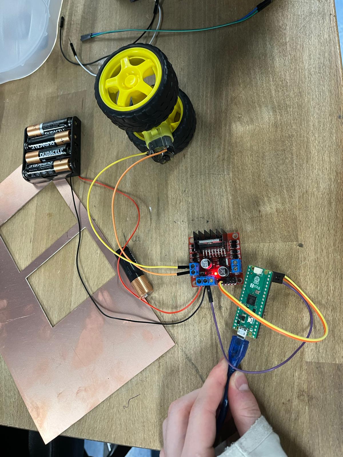
Building a Pico Car
DC Motor + LED
In this experiment, we control:
- An LED (visual feedback)
- A DC motor using the L298N motor driver
The system demonstrates:
- GPIO output control
- Motor direction switching
- Timing-based behavior
Components Used
| Component | Purpose |
|---|---|
| Raspberry Pi Pico W | Main controller |
| L298N Motor Driver | Controls motor direction |
| DC Motor | Movement |
| LED + 220Ω resistor | Status indication |
| External Battery (5–9V) | Motor power |
Wiring
LED Connection
| Component | Connect To |
|---|---|
| LED long leg | GP16 |
| LED short leg | 220Ω resistor → GND |
Motor Driver (L298N)
| L298N Pin | Connect To |
|---|---|
| IN1 | GP14 |
| IN2 | GP15 |
| OUT1 / OUT2 | DC Motor |
| 12V | External battery (+) |
| GND | Battery (-) + Pico GND |
Important:
Do NOT power the motor from the Pico
Always use an external power supply
Control Logic
| Action | IN1 | IN2 |
|---|---|---|
| Forward | 1 | 0 |
| Backward | 0 | 1 |
| Stop | 0 | 0 |
from machine import Pin
import time

# LED setup
led = Pin(16, Pin.OUT)

# Motor control pins
motor_in1 = Pin(14, Pin.OUT)
motor_in2 = Pin(15, Pin.OUT)

while True:
    # LED ON + Motor Forward
    led.on()
    motor_in1.value(1)
    motor_in2.value(0)
    time.sleep(2)

    # Motor Backward
    motor_in1.value(0)
    motor_in2.value(1)
    time.sleep(2)

    # Stop everything
    motor_in1.value(0)
    motor_in2.value(0)
    led.off()
    time.sleep(1)
Here, the LED turns ON when the system is active. The motor rotates forward for 2 seconds. Then backward for 2 seconds. Then stops for 1 second. The loop repeats indefinitely.
Rotating the Car (180° Left & Right)
In this experiment, we use two DC motors to rotate the car in place:
- Rotate right (180°)
- Rotate left (180°)
This is done by making both motors spin in the same direction, causing the robot to pivot instead of moving forward.
Components Used
| Component | Purpose |
|---|---|
| Raspberry Pi Pico W | Main controller |
| L298N Motor Driver | Controls both motors |
| 2× DC Motors | Movement |
| External Battery (5–9V) | Motor power |
Wiring (Motors)
| Motor | L298N Pin | Pico Pin |
|---|---|---|
| Motor 1 | IN1 / IN2 | GP14 / GP15 |
| Motor 2 | IN3 / IN4 | GP16 / GP17 |
Control Logic
Rotate Right (Clockwise)
| Motor | Direction |
|---|---|
| Motor 1 | Forward |
| Motor 2 | Forward |
Rotate Left (Counterclockwise)
| Motor | Direction |
|---|---|
| Motor 1 | Backward |
| Motor 2 | Backward |
Since both motors spin the same way, the robot spins in place instead of moving forward.
from machine import Pin
import time

# Motor 1
motor1_in1 = Pin(14, Pin.OUT)
motor1_in2 = Pin(15, Pin.OUT)

# Motor 2
motor2_in1 = Pin(16, Pin.OUT)
motor2_in2 = Pin(17, Pin.OUT)

def stop():
    motor1_in1.value(0)
    motor1_in2.value(0)
    motor2_in1.value(0)
    motor2_in2.value(0)

def rotate_right():
    # Both motors forward
    motor1_in1.value(1)
    motor1_in2.value(0)
    motor2_in1.value(1)
    motor2_in2.value(0)
    time.sleep(2)
    stop()

def rotate_left():
    # Both motors backward
    motor1_in1.value(0)
    motor1_in2.value(1)
    motor2_in1.value(0)
    motor2_in2.value(1)
    time.sleep(2)
    stop()

while True:
    rotate_right()
    time.sleep(1)

    rotate_left()
    time.sleep(1)
Here, The robot Spins right for 2 seconds (~180°). Stops briefly. Spins left for 2 seconds (~180°). This loop continues forever.
Pico W Rotation Video
L298N Motor Driver Architecture
The L298N is a motor driver that lets a microcontroller (like the Pico) control DC motors safely and efficiently.
Why do we need it?
- GPIO pins → very low power
- Motors → need high current + higher voltage
The L298N acts as a power bridge between them.
Core Idea: H-Bridge
At the heart of the L298N is something called an H-Bridge.
This circuit lets you:
- Spin a motor forward
- Spin it backward
Direction Control
| IN1 | IN2 | Motor Behavior |
|---|---|---|
| 1 | 0 | Forward |
| 0 | 1 | Backward |
| 0 | 0 | Stop |
Key Pins Overview
Control Pins
| Pin | Function |
|---|---|
| IN1, IN2 | Control Motor A direction |
| IN3, IN4 | Control Motor B direction |
| ENA | Enable / speed control (Motor A) |
| ENB | Enable / speed control (Motor B) |
Output Pins
| Pin | Function |
|---|---|
| OUT1, OUT2 | Motor A connection |
| OUT3, OUT4 | Motor B connection |
Power Pins
| Pin | Function |
|---|---|
| VCC | Motor power (5–35V) |
| GND | Common ground |
| 5V / VSS | Logic power |
Speed Control (PWM)
The ENA / ENB pins can take a PWM signal.
This allows:
- Slow motor → low duty cycle
- Fast motor → high duty cycle
This is how you control speed, not just ON/OFF.
Important Characteristics
- Voltage range: ~4.5V to 46V
- Current: ~2A per motor
- Built-in protection diodes
- Can control 2 motors at once
Limitations (Very Important)
The L298N is not very efficient.
- Uses older transistor design (BJT)
- Loses energy as heat
- Efficiency: ~40–50%
That’s why it can get hot.
Better Alternatives
- TB6612FNG
- L293D (slightly better)
But:
L298N is still great for learning and prototyping.
Program Code Example:
from machine import Pin
import time

# Motor control pins
motor_in1 = Pin(14, Pin.OUT)
motor_in2 = Pin(15, Pin.OUT)

def rotate_motor_right():
    motor_in1.value(1)
    motor_in2.value(0)
    print("Motor rotating right (clockwise)")

def rotate_motor_left():
    motor_in1.value(0)
    motor_in2.value(1)
    print("Motor rotating left (counterclockwise)")

while True:
    rotate_motor_right()
    time.sleep(2)

    rotate_motor_left()
    time.sleep(2)
Power Management (Pico + L298N + 2 Motors)
When working with motors, power is the #1 thing that can go wrong.
- Motors need high current
- Pico provides very low current
If you power things incorrectly, you can:
- Reset the Pico
- Overheat the driver
- Damage components
Power Distribution
Pico Power
| Method | Voltage |
|---|---|
| USB | 5V |
| VSYS pin | 1.8V – 5.5V |
Motor Power (Through L298N)
| Component | Voltage |
|---|---|
| L298N (motor side) | ~5V – 12V |
| DC Motors | Depends on motor |
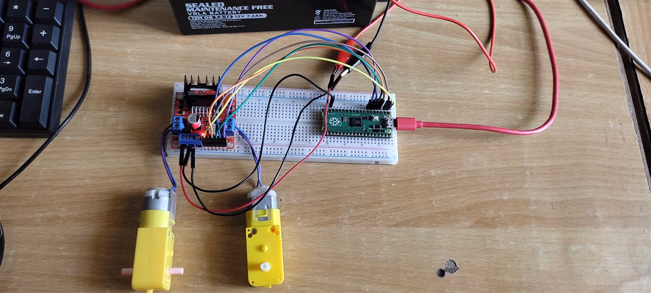
Overall Look After All These Steps
Files
You can access to the files of this week from the link below.