Week 9: Input Devices
Planted March 24, 2026
Input devices were an interesting week particularly due to two things: 1. in my embedded systems work I have been generally an output guy so it was cool to work with input devices, it was a novelty; 2. I got to experiment with an interesting idea in PCB design, using mathematical strength of FRep to help AI design board, for sensor board not main board of course that was in KiCad.
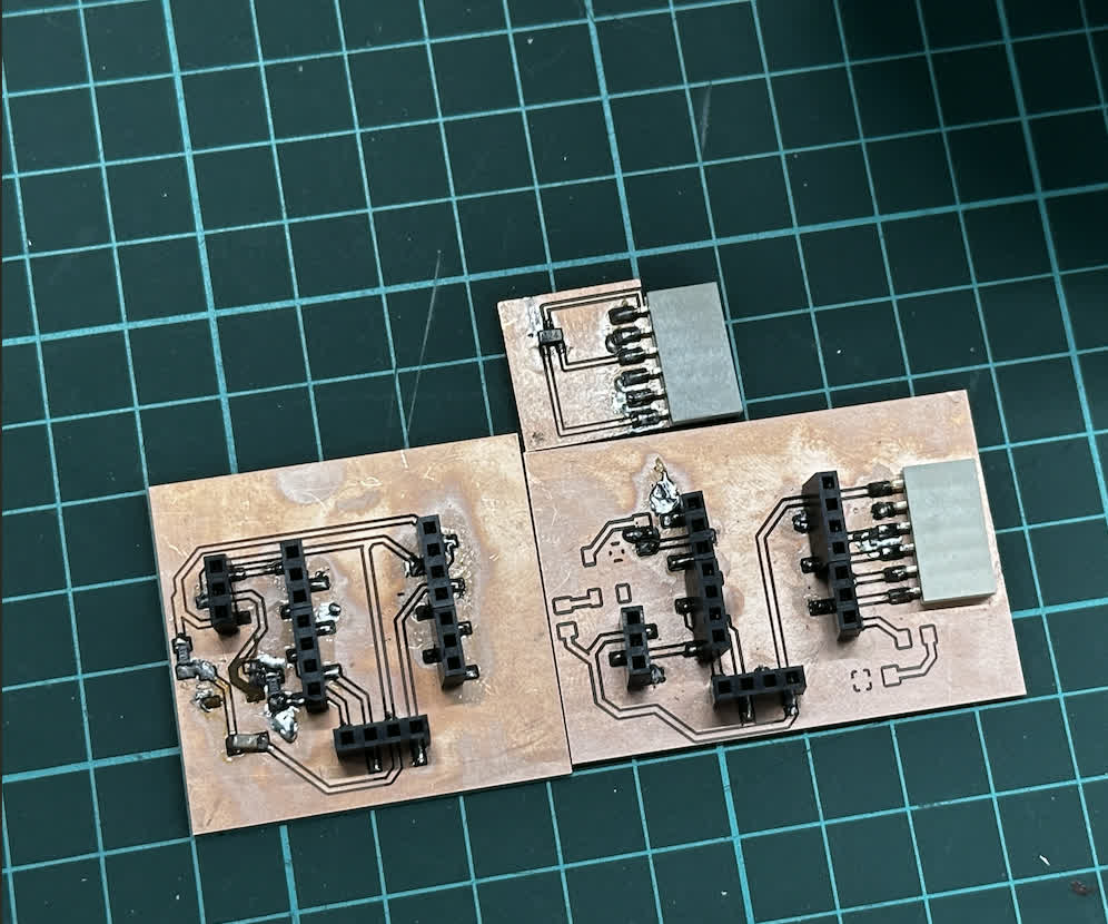
Hero Shots of my Boards

Figure 1: Top Hall Effect sensor board; Bottom Left XIAO ESP32C3 dev board with access to analog pins; Bottom Right: multi functional board v2 for XIAO ESP32C3
Genesis
Touch Sensor
#define TOUCH_PIN 10

void setup() {
  Serial.begin(115200);
  pinMode(TOUCH_PIN, INPUT);
}

void loop() {
  if (digitalRead(TOUCH_PIN)) {
    Serial.println("Touched");
  } else {
    Serial.println("Not touched");
  }
  delay(100);
}
For this first test I kept everything simple: the touch pad is read as a plain digital input. When the sensor is touched, the MCU immediately flips to Touched on the serial monitor; when released it returns to Not touched. I also noticed there is a short “settling” moment right after applying touch, so for any real keyboard use I would add debouncing / a small time window before treating it as a valid press.
Motion Sensor
#define PIR_PIN 9

void setup() {
  Serial.begin(115200);
  pinMode(PIR_PIN, INPUT);  // PIR output
}

void loop() {
  int motion = digitalRead(PIR_PIN);

  if (motion == HIGH) {
    Serial.println("Motion detected!");
  } else {
    Serial.println("No motion");
  }

  delay(200);
}
For the motion sensor I used the PIR module output as a digital signal (HIGH/LOW). The behavior was very consistent when moving in front of the sensor, and it gave a clear, single “Motion detected!” event that I could then use as a trigger for LEDs, logging, or other input-driven logic. One improvement for the final version would be to add a simple cooldown timer so the same movement doesn’t spam repeated detections.
Gyro
#include <Wire.h>

#define SDA_PIN 6
#define SCL_PIN 7
#define MPU_ADDR 0x68

void setup() {
  Serial.begin(115200);

  // Start I2C on custom pins
  Wire.begin(SDA_PIN, SCL_PIN);

  // Wake up MPU6050
  Wire.beginTransmission(MPU_ADDR);
  Wire.write(0x6B);  // Power management register
  Wire.write(0);     // Wake up
  Wire.endTransmission(true);

  Serial.println("MPU6050 Ready");
}

void loop() {
  Wire.beginTransmission(MPU_ADDR);
  Wire.write(0x43); // Gyro data start register
  Wire.endTransmission(false);
  Wire.requestFrom(MPU_ADDR, 6, true);

  int16_t gx = Wire.read() << 8 | Wire.read();
  int16_t gy = Wire.read() << 8 | Wire.read();
  int16_t gz = Wire.read() << 8 | Wire.read();

  Serial.print("Gyro X: "); Serial.print(gx);
  Serial.print(" | Y: "); Serial.print(gy);
  Serial.print(" | Z: "); Serial.println(gz);

  delay(500);
}
The gyro test focused on validating the I2C wiring and getting believable raw data. I printed Gyro X / Y / Z values as integers directly from the MPU6050 registers; once the board was still, the readings stayed fairly stable, and when I rotated the module the values clearly changed direction and magnitude.
Capacitive touch
Since this is relevant to my final I wanted to include it here. I experimented with the SAMD21 using the Adafruit_FreeTouch library and treated the five touch channels as a “chord input”. Each channel is thresholded (THRESHOLD 800) and then combined into a 5-bit value, which I map to characters in printFromCombo(). In practice this made it much easier to validate the idea: touching multiple pads at once produces a single stable code, and releasing all pads outputs the selected character.
#include <Adafruit_FreeTouch.h>

Adafruit_FreeTouch touch1  = Adafruit_FreeTouch(1,  OVERSAMPLE_4, RESISTOR_50K, FREQ_MODE_NONE);
Adafruit_FreeTouch touch6  = Adafruit_FreeTouch(6,  OVERSAMPLE_4, RESISTOR_50K, FREQ_MODE_NONE);
Adafruit_FreeTouch touch8  = Adafruit_FreeTouch(8,  OVERSAMPLE_4, RESISTOR_50K, FREQ_MODE_NONE);
Adafruit_FreeTouch touch9  = Adafruit_FreeTouch(9,  OVERSAMPLE_4, RESISTOR_50K, FREQ_MODE_NONE);
Adafruit_FreeTouch touch10 = Adafruit_FreeTouch(10, OVERSAMPLE_4, RESISTOR_50K, FREQ_MODE_NONE);

#define THRESHOLD 800

uint8_t currentCombo = 0;
bool touching = false;

void setup() {
  Serial.begin(115200);
  while (!Serial);

  touch1.begin();
  touch6.begin();
  touch8.begin();
  touch9.begin();
  touch10.begin();

  Serial.println("Chord Keyboard Ready");
}

// =======================
// COMBO -> CHARACTER MAP
// =======================
void printFromCombo(uint8_t combo) {

  switch(combo) {

    // letters
    case 1:  Serial.print("A"); break;
    case 2:  Serial.print("B"); break;
    case 3:  Serial.print("C"); break;
    case 4:  Serial.print("D"); break;
    case 5:  Serial.print("E"); break;
    case 6:  Serial.print("F"); break;
    case 7:  Serial.print("G"); break;
    case 8:  Serial.print("H"); break;
    case 9:  Serial.print("I"); break;
    case 10: Serial.print("J"); break;
    case 11: Serial.print("K"); break;
    case 12: Serial.print("L"); break;
    case 13: Serial.print("M"); break;
    case 14: Serial.print("N"); break;
    case 15: Serial.print("O"); break;
    case 16: Serial.print("P"); break;
    case 17: Serial.print("Q"); break;
    case 18: Serial.print("R"); break;
    case 19: Serial.print("S"); break;
    case 20: Serial.print("T"); break;
    case 21: Serial.print("U"); break;
    case 22: Serial.print("V"); break;
    case 23: Serial.print("W"); break;
    case 24: Serial.print("X"); break;
    case 25: Serial.print("Y"); break;
    case 26: Serial.print("Z"); break;

    // special keys (use remaining combos)
    case 27: Serial.print(" "); break;     // space
    case 28: Serial.print("<"); break;     // backspace symbol
    case 29: Serial.println(); break;      // enter
  }
}

void loop() {

  uint16_t v1  = touch1.measure();
  uint16_t v6  = touch6.measure();
  uint16_t v8  = touch8.measure();
  uint16_t v9  = touch9.measure();
  uint16_t v10 = touch10.measure();

  bool t1  = v1  > THRESHOLD;
  bool t6  = v6  > THRESHOLD;
  bool t8  = v8  > THRESHOLD;
  bool t9  = v9  > THRESHOLD;
  bool t10 = v10 > THRESHOLD;

  // build 5-bit combo
  uint8_t combo = 0;
  if (t1)  combo |= 1;
  if (t6)  combo |= 2;
  if (t8)  combo |= 4;
  if (t9)  combo |= 8;
  if (t10) combo |= 16;

  // if touching, store combo
  if (combo > 0) {
    touching = true;
    currentCombo = combo;
  }

  // when released → print char
  if (combo == 0 && touching) {
    touching = false;

    printFromCombo(currentCombo);

    currentCombo = 0;
  }

  delay(10);
}
MAX4466 Microphone, Fail Time
This was the fail of this week the MAX4466 microphone although connected to an analog pin and had the correct connections would always yield a value of either -400 or 0 and this was not a pcb or connection issue since other analog devices with similar voltage requirements worked. Will work in the future to figure this out, update when fixed.
Hall Effect
“see bottom of section strange new worlds”
Strange New Worlds
During this weeks open time Adrian talked about his sensor modules and why he made them etc. An important point he said was to do this if you had enough time. To create enough time I decided build a tool I already toyed with in week 6 for faster design.
An MCP server integrating with pcb.py to grant Claude Code the ability of designing correct board using fab components.
This way I’d get to easily design sensor boards and sub-board and since FRep is completely based on mathematical functions it made it a whole lot easier to feed this to AI.
github repo link where you can find fully expressive and detailed docs
MCP
In mcp_server.py, I register tool functions with @mcp.tool().
This lets Claude Code call board-design actions directly.
mcp = FastMCP("frep-pcb")


@mcp.tool()

def render_pcb(code: str, dpi: int = 100) -> Image:

ns = _build_namespace()

exec(code, ns)
The server runs the design code in a controlled namespace, checks outputs,
then calls frep.py to render PNG.
Another key part is validation:
compile and execute code
check required
outputskeysauto-run DRC before saying design is valid
DRC
drc.py does not change pcb.py.
Instead, it injects wrappers for wire() and wirer() to collect trace geometry.
def instrument_namespace(ns):

collector = DRCCollector(ns['wire'], ns['wirer'])

ns['wire'] = collector.wire

ns['wirer'] = collector.wirer

...

return collector
After execution, collected traces/pads are checked for rule violations.
Main checks in current code:
SHORT(different nets crossing on same layer)CLEARANCE(too close traces)OUT_OF_BOUNDSUNCONNECTED_PADZERO_LENGTH_WIRE
Example from DRC loop:
if segments_intersect(*seg_a, *seg_b):

violations.append({

'type': 'SHORT',

'detail': f'Net {net_a} crosses net {net_b} ...',

})
Final outputs
The final outputs given from the program are 4
- name_edge_cuts.jpg
- name_traces.jpg
- name_traces_textless.jpg
- name.jpg below are all 4
name_edge_cuts
 name_traces
 name_traces_textless
 name
name
 name provides and expressive image showing all the board and purpose of pins, though the default, tx rx config of the six pin connector is technically incorrect here. The traces textless and traces provide two options for the milling traces. Finally, the edge cuts layers is for the edge cuts.
After that the CAM is done in mods ce.
Below is the manufactured and soldered board, I was testing out a new iron when doing this so there might have been some sloppiness on my part, but it passed the multimeter test so it was good to go

code test
#define HALL_PIN 2

void setup() {
  Serial.begin(115200);
  pinMode(HALL_PIN, INPUT);
}

void loop() {
  int sensorValue = digitalRead(HALL_PIN);

  if (sensorValue == HIGH) {
    Serial.println("Magnet Detected");
  } else {
    Serial.println("Magnet Not Detected");
  }

  delay(200);
}
Overall this was another exciting and fun week where I got to try out new things contextually and semi contextually relevant to the week!