Week 8: Electronics Production
Planted March 17, 2026
This week is electronic production. As for people who has seen my previous weeks I have had some experience with this hence I wanted to have a well done and proper best pratices pcb manufacture experience week.
Group assignment
CAM
To focus on the workflow the first time around I decided to manufacture the hello board of a controller I wanted to work with for some time the T412.
First I went into inkscaped to resize page to selection, which wasn’t required in this case, but was a part of the workflow so I included it.
 Then it was onto mods for the preprocessing
 I chose the SRM 20 PCB for the workflow as that is my machine
 First I selected the front cu to process
 Then I entered the appropriate bit information into the v-bit calculator

next I adjusted the milling machine settings mainly making the origin zero and adjusting the speed
 finally before getting to the path calculation I inverted the SVG since that is required in the program as well
 I followed similar steps for edge cuts and got the rml’s and then emailed them to the PCB milling computer for fabrication
Manufacture
Let’s meet our cast: Double sided tape, tape measure, brush, bits, copper fr1 plate, sandpaper.
 pre-processing: I sanded the FR1 plate with the sandpaper to get rid of the protective layer on top of it.
It was onto the machine first I fetched my double sided tape and placed it on the back of my FR1

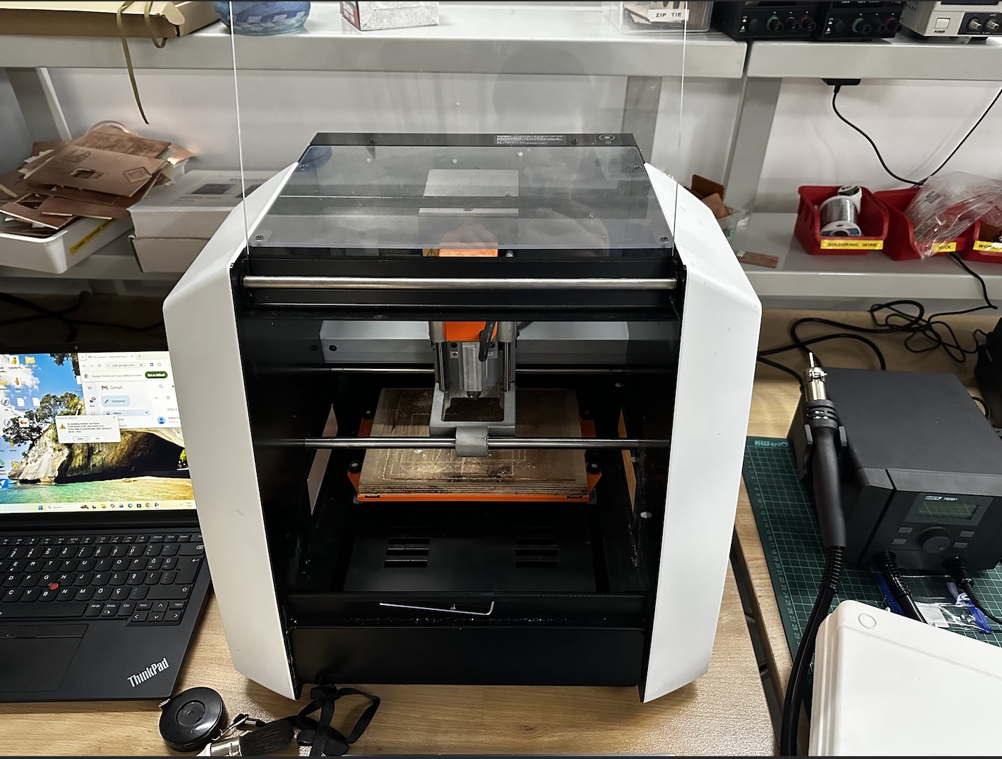
Now it’s time to greet the machine the Roland SRM20!

A close shot of the plate and the inside of the machine
 It was onto getting the FR1 and placing it on a secure location on the bed

next I inserted the v-bit into the given slot by pushing it in there and then fastening it with the allen key

next it was onto setting the x y and z I used the program below to do that

The v-bit in the machine

first I lowered the bit to an appropriate height right above the FR1 plate

next using the allen key I unfastened it and using one finger carefully lowered it to just above touching the FR1 and then re-fastened it. Then set the XYZ there

next it was onto cutting, small note: don’t forget to raise the v-bit slightly before the spindle start spinning.
Cutting vid
the edge cuts came out perfectly, to check I slightly removed the debris on it using the brush

next it was onto the edge cuts where I followed similar steps in order to position the 2.0 mm edge cuts tip as below

since in the first cut the plate wasn’t stabilized quite correctly, this fail occured

below is a remanufacture and successful result

out of the machine

then it was onto washing the board to remove what might be in there

now we are done with the manufacture and onto solder
Soldering
An overview of the station, let’s meet our cast again! Soldering iron, air filter, flux, rosin, solder and gloves for safety
 Before soldering I prepared a paper with the components per my mentor Sedat’s advice since components are small and can be easily lost dropped etc

a photo from soldering

final result

After this to test if the board was soldered I ran the LED and Continuity tests on the board and I saw no errors.
Before this week I had run some experiments with production for this week hence I decided to include the one I am most proud of here as well
Other Board
Below is the said other board “the multifunctional board” as I like to call it.
Videos
WS2812 RGB test
Servo + RGB
OLED: Conway’s Game of Life
OLED: Flocking simulation
OLED: 3D wireframe cube
Notes
One worked the other unfortunately didn’t, it got burnt by my sloppy" hands during soldering .(

Hero shots for the board
