Week 7: Computer-Controlled Machining
Planted March 11, 2026
Assignment
Design and CNC mill a large object demonstrating the full CAD → CAM → machine workflow. I made a parametric press-fit stool: two A-frame leg panels slot through channels in the seat, assembling without fasteners or glue.
Design — Fusion 360
The stool is three parts cut from one 700×1000 mm sheet of 20 mm birch plywood: a seat and two identical trapezoidal leg panels. A single materialThickness = 20 mm parameter drives all slot widths and depths.
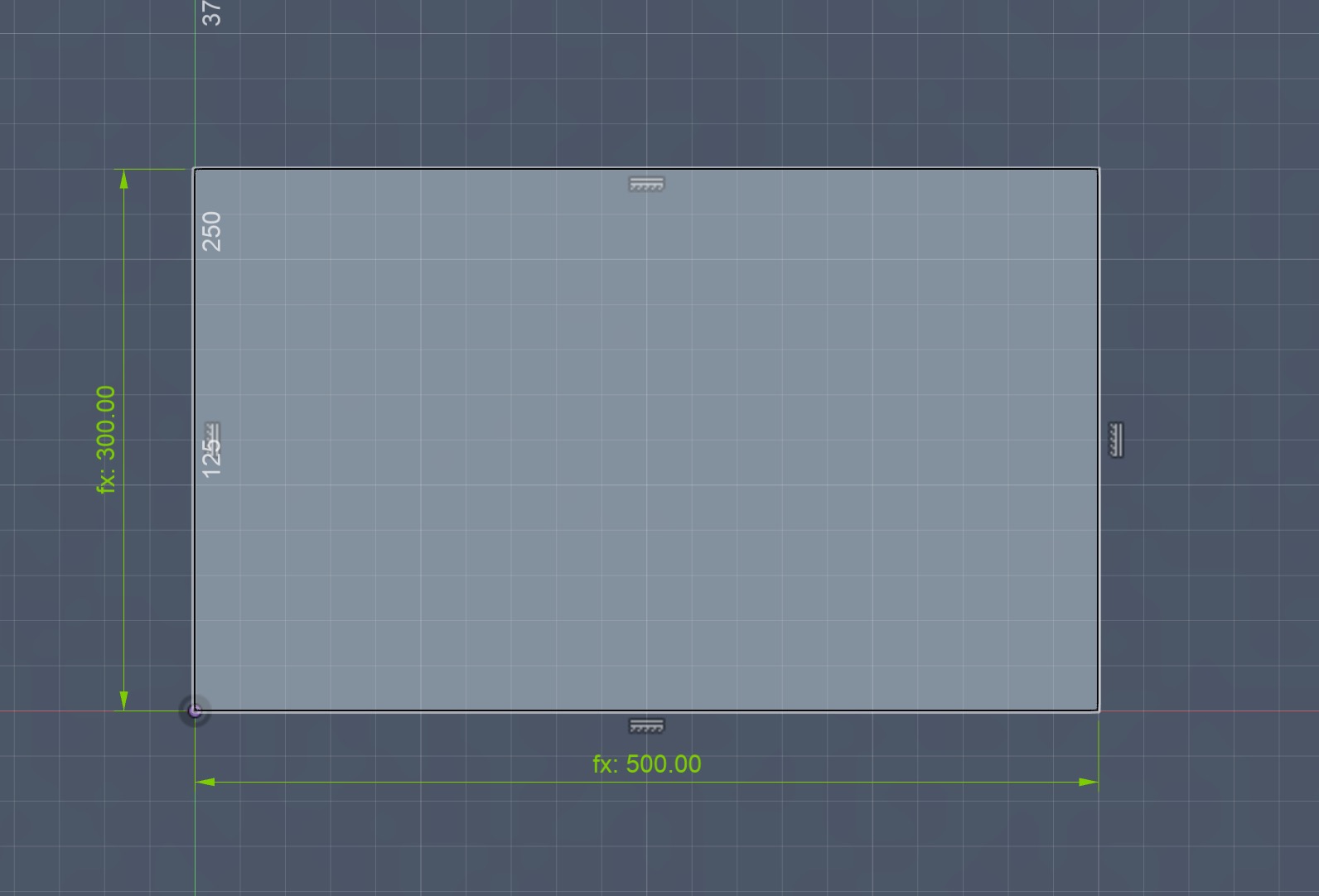
Seat — 500 × 300 mm rectangle with two 150 × 10 mm through-slots, positioned ±125 mm from the centreline. Slot width matches the bit diameter for a snug press-fit.
Legs — Trapezoidal A-frame, 350 × 300 mm outer, with a 250 × 200 mm inner cutout. The wider base prevents lateral racking.
Key parameters
All the main dimensions are driven by user parameters in Fusion 360:
| Parameter | Value | Notes |
|---|---|---|
mat_width | 10 mm | width of the radial material ring |
table_width | 300 mm | overall tabletop width |
table_height | 300 mm | overall tabletop depth |
join_len | 50 mm | length of each finger joint |
leg_height | 500 mm | total leg height before adjustments |
leg_width | 200 mm | leg footprint width |
leg_cutout | 150 mm | inner cutout width in the leg |
leg_cutout_height | 250 mm | inner cutout height in the leg |
dist_between_join | 50 mm | spacing between finger joints |
dist_between_outer | 50 mm | spacing from outer edge to first joint |
clearance | 0.3 mm | extra gap for press-fit tolerance |
arc_thick | 350 mm | radius/thickness driving the arc profile |
dog | 6 mm | dog-bone radius matching the cutter |
first I created the initial base of the stool

then I extruded it
 for the legs first I created the initial rectangle for the leg

then I decided to give it a smaller size since 500 mm is to tall for a stool so I adjusted to as below

Then I added the pocket seen below to give it a more aesthetic look

after some adjustments below ğs the final version of the leg sketch

Below is the layed out version

and the sample assembly process where I first lifted up the base and then connected the base


Though I made some iterations after this to create a more interesting and better product.
First I adjusted the base to this circular triangle geometry to give it a more interesting look

next I realized that with the current joinery structure the legs would fall out hence I opted for a finger joint structure and adjusted the legs as below

finally I added a dog bone fillet to the slots in order for the male parts of the joints to pass easier

CAM — VCarve Pro 12.507
All three parts nested on a 700 × 1000 mm sheet. Two toolpath operations with a 6 mm flat end mill:
- Pocket 1 — 10 mm deep slots on the seat underside (2 × 5 mm passes)
- Profile 15 — 10 mm depth to release all parts (2 × 5.04 mm passes, auto-tabs)
| Setting | Value |
|---|---|
| Tool | 6 mm flat end mill |
| Spindle speed | ~24 000 RPM |
| Feed rate | ~2 500 mm/min |
| Plunge rate | ~800 mm/min |
| Pass depth | 5.04 mm |
| Post processor | G-Code mm (*.tap) |

Machining — ARC-CNC Mach3
The machine we used was ARC-CNC a locally produced machine in Turkey by a small operation in Bursa by the company ARC CNC. Spesifically we have the Mach3 model.
overview of machine

overview of control panel

Next it was onto machining. I went to the CNC room with my fellow student Omer to ensure if there was any injury there was the other person to call the necessary parties.
a safety first photo

Before starting I cleaned out the sacrificial board of the debris it possesed from a previous use

First we placed and stabilized the material using screws

next it was onto placing the bit corretly
first I inserted into there

next I stabilized and placed and secured the bit into the socket

Then it was onto the cutting
photo from the software as the pockets were being cut

Below are two short clips from the machining:
final result

issues: since I used 1.08 thick wood not 1 mm thick wood the joints didn’t pass through the slots hence it was not assembleable

Hence I had to do some post processing. Thanks to the Dremel at the Lab I was able to take of the extras of the male parts of the finger joints and is was onto the press fit assmembly
Assembly & Result
Press-fit only — no glue, no screws. Legs slot through the seat and stand on their own geometry. Fit was snug on first attempt.
