Week 4: Embedded Programming
Planted February 12, 2026
Overview
This week was all about trying different workflows for me. Of all the Fab Academy weeks so far, this was the one I had the most experience in, so it was quite smooth sailing. I had some previous experience with embedded programming though I had not extensively worked on it until this week, so I decided to start out with the digital and then go to the physical. But before that I browsed through a select microcontrollers’ datasheets, including the Raspberry Pi Pico.
Group assignment
Pico and it’s data sheet
Before designing or programming any board, understanding the microcontroller through its datasheet is essential. For this week, I examined the RP2040 datasheet.
Pi Pico 101
The Pico is built around the RP2040 microcontroller, mounted on a 51×21 mm castellated PCB that exposes most of the chip’s I/O. It is designed as a low-cost but flexible development platform with:
- Dual-core Cortex-M0+ @ up to 133 MHz
- 264 KB SRAM
- 2 MB QSPI Flash
- USB 1.1 (device + host)
- **26 multi-function GPIO pins (3 Analog to Digital (ADC) pins)

Why is the chip called RP2040?
The name RP2040 is not arbitrary—each part encodes a technical detail about the chip:

- RP — Raspberry Pi (the manufacturer).
- 2 — Number of processor cores (the RP2040 has two ARM Cortex-M0+ cores).
- 0 (first) — This digit loosely indicates the type of ARM core. “0” stands for the M0 family (e.g. Cortex-M0, M0+): the simplest, most power‑efficient ARM cores. So this “0” is telling you “it’s an M0-class core,” as opposed to a more capable M3, M4, or M7. The RP2040 uses Cortex-M0+, so the first 0 fits that scheme.
- 4 — Derived from RAM size as floor(log₂(ram / 16k)). The RP2040 has 264 KB SRAM; 264/16 = 16.5, log₂(16) = 4, so the digit is 4.
- 0 (last) — This one encodes on-chip non-volatile memory (flash) using floor(log₂(nonvolatile / 16k)), or 0 if the chip has none. “Non-volatile” means memory that keeps your program when power is off. The RP2040 has no flash on the chip itself—your code lives on a separate QSPI flash chip on the board (e.g. 2 MB). So the last 0 literally means “zero on-chip non-volatile storage.”
So the name is a compact summary: Raspberry Pi, 2 cores, M0-type core, RAM encoding 4, and no on-chip nonvolatile memory.
RP2040 block diagram
The block diagram below shows how the main parts of the chip are connected:

- Processors (Proc0, Proc1) — The two ARM Cortex-M0+ cores, with an interrupt controller and SIO (Single-Cycle I/O) for fast access to GPIO and the rest of the system.
- Clock — An internal oscillator and external crystal feed two PLLs, which generate the system and peripheral clocks.
- GPIO [29:0] — 30 multi-function pins; many can be routed to peripherals (SPI×2, I2C×2, UART×2, PWM, ADC, timer, RTC, etc.) or to the PIO blocks.
- PIO0 & PIO1 — Programmable I/O state machines: small, dedicated processors that can bit-bang protocols and handle precise timing without loading the main cores.
- Memory — SRAM (264 KB in several blocks), ROM (bootloader), and XIP/cache for executing code from external QSPI flash. There is no on-chip flash; the “0” in RP2040 reflects that.
- Bus fabric — The central interconnect linking cores, memory, peripherals, and USB so they can exchange data.
- USB — Full-speed USB 1.1 controller (device and host). SWD provides the debug interface.
- QSPI — Interface to external flash (e.g. 2 MB), used for program storage and execute-in-place (XIP).
Together, the naming diagram and block diagram show both what the name means and how the chip is built.
Pins
The Pico exposes 26 GPIOs, but some RP2040 pins are reserved for internal board functions:
- GPIO25: onboard LED
- GPIO24: VBUS sense
- GPIO23: controls SMPS power-save mode
- GPIO29 (ADC3): reads VSYS/3 for battery/voltage monitoring
No GPIO pins on the Pico crucial for designing embedded systems, in my opinion:
- VBUS: 5V input from USB
- VSYS: main input (1.8–5.5 V) into the buck-boost regulator
- 3V3_EN: disable 3.3 V rail
- 3V3: regulated supply output (max recommended external load: ~300 mA)
- ADC_VREF: filtered reference for ADC
- AGND: analog ground
- RUN: reset/enable pin

Operational and Electrical limits
Voltage Conditions
- VSYS: 1.8–5.5 V
- VBUS: 5 V ±10%
- GPIO Voltage: fixed at 3.3 V (NOT 5-V tolerant)
Temperature
- Operating range: −20°C to +85°C, recommended max ambient: 70°C
Power
The Pico includes a buck-boost SMPS capable of maintaining a stable 3.3 V output regardless of whether VSYS is above or below 3.3 V. The system accommodates a wide range of power sources, such as:
- USB 5V
- Single Li-Ion cells (3.0–4.2 V)
- 3× AA cells
Below is the Pi Pico usb circuit:

ADC
The Pico’s ADC is affected by the fact that ADC_VREF is derived from 3.3 V via an RC filter, leading to:
- Some inherent noise
- A ~30 mV offset due to current draw through the 200Ω resistor
- Reverse-diode protection on GPIO26–29 means input voltage must not exceed 3.3 V + 0.3 V
USB, SWD, and Programming
The Pico supports:
- USB Mass Storage bootloader via BOOTSEL (drag-and-drop UF2 files)
- SWD debugging through a 3-pin head
Dimensions
- 51 × 21 mm PCB
- 1 mm thick
- With castellated edges, half-plated holes along the edge (so it can be soldered onto another PCB) , for SMT (surface mount technology) reflow

Comparison of the Processing Power of the RP2040
| Computer | CPU | Speed (MHz) | Memory | Bits | Cores |
|---|---|---|---|---|---|
| Apple II | MOS 6502 | 1 | 48 KB | 8 | 1 |
| Commodore 64 | MOS 6510 | 1.023 | 64 KB | 8 | 1 |
| ESP8266 | Xtensa L106 | 80 | 80 KB | 32 | 1 |
| ESP32 | Xtensa LX6 | 240 | 520 KB | 32 | 2 |
| RP2040 | ARM Cortex-M0+ | 133 | 264 KB | 32 | 2 |
| Raspberry Pi 3 | ARM Cortex-A53 | 1200 | 1 GB | 64 | 4 |
| Pi 4 | ARM Cortex-A72 | 1500 | 2/4/8 GB | 64 | 4 |
| Raspberry Pi 5 | ARM Cortex-A76 | 2400 | 4/8 GB | 64 | 4 |
101
The Digital
I decided to start out with the most familiar microcontroller to me the Raspberry Pi Pico. For the virtual environment I was going to use I went with WokWi since I knew it would provide a stable experience.
Genesis
I started out with getting to know the environment. It was composed of a two interface setup the left side for the code and the right side for the electronics. Using the add button I added a led and a button to create a simple button led circuit where the button click toggle’s the open status of the led.
Below is the circuit diagram and the code.
Code:
Import Libraries
from machine import Pin
import time
I imported the necessary modules:
Pinfrom themachinemodule to control GPIO pinstimefor delays and timing functions
Initialize LED Pin
# Create a Pin object for an LED on GPIO1, set as output
led = Pin(1, Pin.OUT)

# Start with the LED turned OFF
led.value(0)
Then set up the LED on GPIO pin 1 as an output and ensure it starts in the OFF state (0).
Initialize Button Pin
# Create a Pin object for a button on GPIO14
# Pin.PULL_UP means the pin is normally HIGH (1), becomes LOW (0) when the button is pressed
button = Pin(14, Pin.IN, Pin.PULL_UP)
Then I configured the button on GPIO pin 14 as an input with internal pull-up resistor enabled.
- Unpressed: Pin reads HIGH (1)
- Pressed: Pin reads LOW (0) as the button connects to ground
Initialize State Variables
# We keep track of the previous button state to detect *press events*
last_button_state = 1

# This variable remembers whether the LED is currently ON or OFF
led_state = False
Then set up two tracking variables:
last_button_state: Stores the previous button reading (starts at 1 for unpressed)led_state: Tracks whether the LED is currently on or off (starts False/OFF)
Main Loop - Read Button State
while True:
    # Read the current state of the button
    button_state = button.value()
The infinite loop continuously monitors the button state by reading its current value.
Edge Detection - Detect Button Press
    # Detect a "falling edge": last was HIGH (1), now it's LOW (0)
    # This means the button has just been PRESSED
    if last_button_state == 1 and button_state == 0:
The I set up the Falling edge detection which identifies the exact moment when the button transitions from unpressed (HIGH) to pressed (LOW). This ensures we only trigger once per press, not continuously while the button is held down.
Toggle LED State
        # Toggle the LED state
        # If it was False → becomes True
        # If it was True → becomes False
        led_state = not led_state

        # Apply the new LED state to the physical LED pin
        led.value(led_state)
When a button press is detected:
- Flip the
led_statevariable using thenotoperator - Apply the new state to the physical LED pin
Debug Output
        # Print messages for debugging / checking state
        if led_state:
            print("Button pressed - LED ON")
        else:
            print("Button pressed - LED OFF")
Print status messages to help with debugging and confirm the LED state changes.
Debounce Delay
        # A short delay to avoid double-counting the same press
        # (simple debounce)
        time.sleep(0.3)
I added a debounce time of 300 milliseconds after detecting a press. This debounce delay prevents mechanical button bounce from triggering multiple state changes from a single physical press.
Update Button State Memory
    # Update the memory of the last state
    last_button_state = button_state
Store the current button reading for comparison in the next loop iteration. This is essential for edge detection.
Polling Delay
    # Small delay to reduce CPU usage and improve stability
    time.sleep(0.01)
Added a 10-millisecond delay in the main loop to:
- Reduce CPU usage (instead of polling as fast as possible)
- Maintain system stability
- Still provide responsive button detection
Complete Code
from machine import Pin
import time

led = Pin(1, Pin.OUT)
led.value(0)

button = Pin(14, Pin.IN, Pin.PULL_UP)

last_button_state = 1
led_state = False

while True:
    button_state = button.value()

    if last_button_state == 1 and button_state == 0:
        led_state = not led_state
        led.value(led_state)

        if led_state:
            print("Button pressed - LED ON")
        else:
            print("Button pressed - LED OFF")

        time.sleep(0.3)

    last_button_state = button_state
    time.sleep(0.01)
Circuit

The circuit connects a purple LED to GPIO1 on the Raspberry Pi Pico with a current-limiting resistor in series, then to ground. A push button connects to GPIO14 with the other side grounded. The Pico’s internal pull-up resistor keeps GPIO14 high when the button is not pressed. When pressed, the button pulls GPIO14 to ground (LOW). The code detects this transition from HIGH to LOW and toggles the LED state each time the button is pressed.
Video
Communication
Then I moved onto adding an I2C device to try to interact with a device using communication protocol.
To explain it simply, I2C (read as I squared C) is a two-wire serial communication protocol (SCL for clock, SDA for data) that lets multiple devices share the same bus. Each device has a unique address, allowing the microcontroller to select which one to read from or write to.
On the Pico there are 2 I2C busses, networks 0 and 1. I decided to connect my chosen devices SDA and SCL pins to GP2, GP3 which constituted that it was on network 1.
My chosen I2C device was an OLED, specifically and SSD1306. To program it though I had to import the SSD1306 library into the WokWi environment by adding a file with the libraries codes into the environment. After that I setup a system which linked up the OLED to the button as well. When the button was first clicked the button would read IdeaLab, as the LED was on as well, and on the next click the button would read Fablab, as the LED is off, as the LED alternates between on and off the OLED alternates between IdeaLab and Fablab.
Below is my code and circuit diagram
Code
Import Libraries
from machine import Pin, I2C
from ssd1306 import SSD1306_I2C
import utime
I import the Pin and I2C classes from the machine module to control GPIO pins and I2C communication. I also import the SSD1306_I2C driver for the OLED display and utime for delays.
Initialize I2C Bus
# Create an I2C object using I2C bus 1
# scl → GPIO3, sda → GPIO2, frequency = 200 kHz
i2c = I2C(1, scl=Pin(3), sda=Pin(2), freq=200000)
I set up the I2C bus on bus 1 with SCL on GPIO3 and SDA on GPIO2. I use a frequency of 200 kHz for communication with the OLED display.
Initialize OLED Display
# Create an OLED object (128x64 resolution)
oled = SSD1306_I2C(128, 64, i2c)
I create an OLED display object with 128x64 pixel resolution, passing in the I2C bus I just configured.
Display Initial Message
# First screen message
oled.fill(0)                 # Clear screen (fill with black)
oled.text("Ready...", 0, 0)  # Write text at x=0, y=0
oled.show()                  # Update the display
I clear the display by filling it with black, then write “Ready…” at the top-left corner (coordinates 0,0). I call show() to actually update the physical display with this content.
Setup LED and Button Pins
led = Pin(1, Pin.OUT)             # LED on GPIO1 as output
button = Pin(14, Pin.IN, Pin.PULL_UP)  # Button on GPIO14 with pull-up resistor
I configure GPIO1 as an output for the LED and GPIO14 as an input with a pull-up resistor for the button.
Initialize State Variables
led_state = False          # LED initially OFF
last_button_state = 1      # Button starts in the unpressed state (HIGH)
screen_toggle = False      # False = IdeaLab, True = Fablab
I set up three state variables: led_state tracks if the LED is on or off, last_button_state remembers the previous button reading for edge detection, and screen_toggle determines which text to display on the OLED.
Main Loop - Read Button State
while True:
    # Read current button state (1 = not pressed, 0 = pressed)
    button_state = button.value()
I start the main loop and continuously read the current button state.
Detect Button Press
    # Detect a falling edge: button goes from HIGH → LOW
    if last_button_state == 1 and button_state == 0:
I detect when the button transitions from HIGH to LOW, which indicates a button press event.
Toggle LED State
        # Toggle LED state (True ↔ False)
        led_state = not led_state
        led.value(led_state)
When I detect a button press, I flip the LED state and apply it to the physical LED pin.
Update OLED Display
        # Update OLED text depending on which screen is active
        oled.fill(0)  # Clear screen
        if screen_toggle:
            oled.text("Fablab", 10, 20)
        else:
            oled.text("IdeaLab", 10, 20)
        oled.show()  # Refresh display
I clear the OLED screen and write either “Fablab” or “IdeaLab” depending on the current screen_toggle state. I position the text at x=10, y=20 to center it better on the display, then call show() to update.
Toggle Screen State
        # Switch to the other screen for next press
        screen_toggle = not screen_toggle
I flip the screen_toggle variable so the next button press will display the other text.
Debounce Delay
        # Small delay to prevent bouncing (debounce)
        utime.sleep(0.25)
I add a 250ms delay to prevent button bounce from causing multiple triggers.
Update Button State Memory
    # Save current button state for next loop
    last_button_state = button_state
I store the current button reading for comparison in the next loop iteration.
Polling Delay
    # Small delay to reduce CPU load
    utime.sleep(0.01)
I add a 10ms delay to reduce CPU usage while keeping the system responsive.
Complete Code
from machine import Pin, I2C
from ssd1306 import SSD1306_I2C
import utime

i2c = I2C(1, scl=Pin(3), sda=Pin(2), freq=200000)
oled = SSD1306_I2C(128, 64, i2c)

oled.fill(0)
oled.text("Ready...", 0, 0)
oled.show()

led = Pin(1, Pin.OUT)
button = Pin(14, Pin.IN, Pin.PULL_UP)

led_state = False
last_button_state = 1
screen_toggle = False

while True:
    button_state = button.value()

    if last_button_state == 1 and button_state == 0:
        led_state = not led_state
        led.value(led_state)

        oled.fill(0)
        if screen_toggle:
            oled.text("Fablab", 10, 20)
        else:
            oled.text("IdeaLab", 10, 20)
        oled.show()

        screen_toggle = not screen_toggle
        utime.sleep(0.25)

    last_button_state = button_state
    utime.sleep(0.01)
How It Works
I built this system to toggle between two displays (“IdeaLab” and “Fablab”) on an OLED screen each time I press a button. The LED provides visual feedback by turning on and off with each press. I use edge detection to ensure each physical button press only triggers one state change, and I alternate which text appears on the OLED screen with each press.
Circuit

The circuit adds an OLED display to the previous button-LED setup. The SSD1306 OLED connects to the Raspberry Pi Pico via I2C: SCL to GPIO3, SDA to GPIO2, VCC to 3.3V power, and GND to ground. The purple LED still connects to GPIO1 through a current-limiting resistor to ground. The push button connects to GPIO14 with the other side grounded, using the Pico’s internal pull-up resistor. When I press the button, the code toggles the LED and alternates the OLED display between showing “IdeaLab” and “Fablab”. The I2C communication at 200kHz allows the Pico to send text and graphics data to the OLED screen.
Video
Physical
Now the digital experimentation was done and it was at this time I switched to the real deal. As a person I love tinkering with hardware, writing the code of it though when it comes to the electronics side my previous experiences have been filled with… all the possible errors on can get to lightly put it. All of the physical coding for the Pico in this section was done from Thonny. Below is my documentation for the physical embedded programming I did.
Pre-Genesis
I was again going to work with a pico. Though this time I had to go through the setup process as well since I didn’t have a set up pico at hand. To sum it up I just got the appropriate uf2 file for my Pico 2 and dragged it onto the designated disk representing it, named RP2350, and it was ready
Genesis
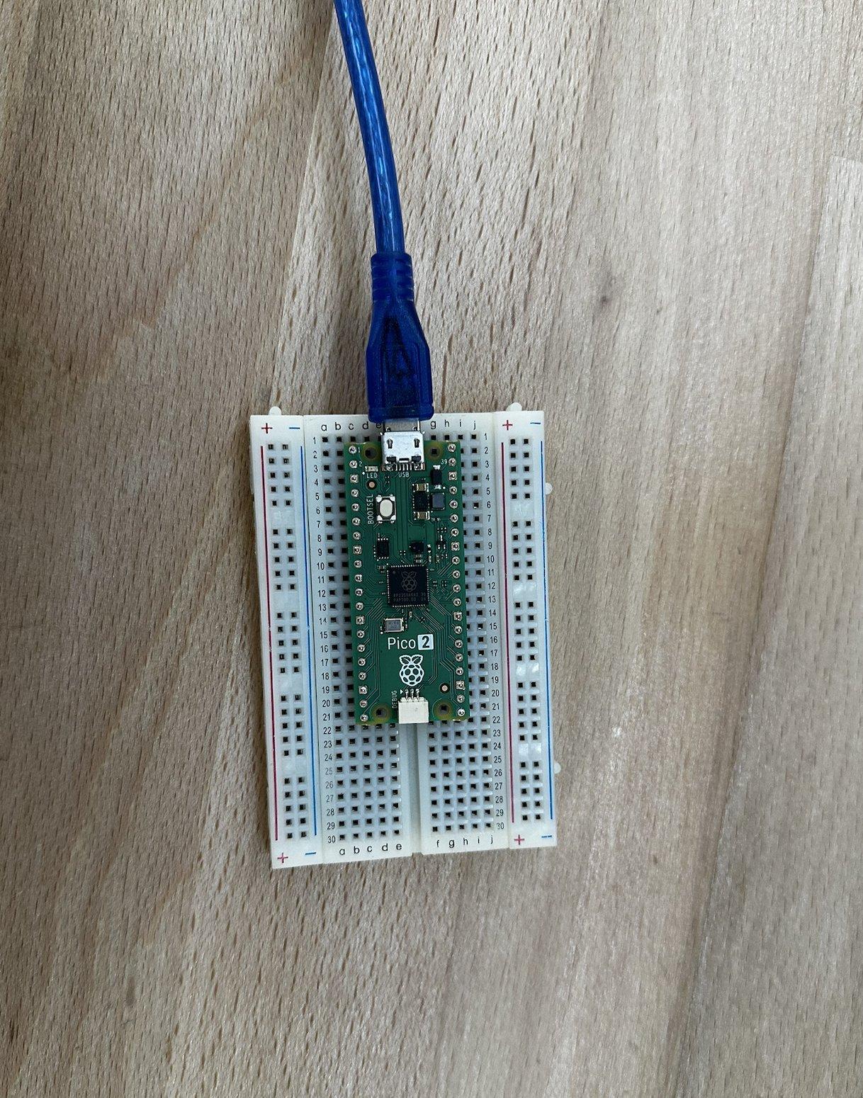
Now it was time for the electronics component. First, I obtained a breadboard and placed my Pico onto it.

Then I connected the LED to the Pico using two male-to-female cables.

Next, I moved on to the first phase of testing—a simple system in which I toggled an LED using the Pico. Below are the working video and code for this test.
Code
from machine import Pin
import time

# Set up LEDs on GPIO pins 2 and 3
led1 = Pin(1, Pin.OUT)

# Blink pattern
while True:
    # Turn both on
    led1.on()

    time.sleep(0.5)

    # Turn both off
    led1.off()

    time.sleep(0.5)

    # Alternate pattern
    led1.on()

    time.sleep(0.3)

    led1.off()

    time.sleep(0.3)
Video
Button
Next, I added the second element: the button. I connected the button using male-to-female cables, with the female ends attached to the button terminals and the male ends connected to the breadboard. The button would toggle the LED. Below is the circuit diagram.

Then I wrote the same code as in the simulation for the button, displayed below.
Code
from machine import Pin
import time


led1 = Pin(1, Pin.OUT)

button = Pin(14, Pin.IN, Pin.PULL_UP)


led1_state = False

prev_button = button.value()

print("Button LED controller ready!")
print("Button on GP14 (physical pin 19) toggles LEDs")

while True:

    curr_button = button.value()


    if prev_button == 1 and curr_button == 0:

        led1_state = not led1_state
        led2_state = not led2_state
        led1.value(led1_state)
        led2.value(led2_state)
        print(f"LEDs: {'ON' if led1_state else 'OFF'}")
        time.sleep(0.05)


    prev_button = curr_button

    time.sleep(0.01)
Video
OLED
Finally, it was time to complete the communication protocol requirement for the week. Using male-to-female cables, I connected the OLED to the Pico via the breadboard, connecting the SCK and SDA pins to the SCL and SDA pins on the Pico and powering the OLED through the VCC and GND pins. Below is the circuit.

Then I wrote a similar program as in the simulation, displayed below, and created a functioning circuit where the button toggles what’s displayed on the OLED and whether the LED is lit. Below is the code and the video.
Code
from machine import Pin, I2C
import time
import ssd1306

led = Pin(1, Pin.OUT)
button = Pin(14, Pin.IN, Pin.PULL_UP)

i2c = I2C(1, scl=Pin(3), sda=Pin(2), freq=400000)
oled = ssd1306.SSD1306_I2C(128, 64, i2c)

led_state = False
message_state = 0
prev_button = button.value()

oled.fill(0)
oled.text("IDEALAB", 30, 28, 1)
oled.show()

while True:
    curr_button = button.value()
    if prev_button == 1 and curr_button == 0:
        led_state = not led_state
        led.value(led_state)

        message_state = 1 - message_state
        oled.fill(0)
        if message_state == 0:
            oled.text("IDEALAB", 30, 28, 1)
        else:
            oled.text("FABLAB", 35, 28, 1)
        oled.show()

        time.sleep(0.05)
    prev_button = curr_button
    time.sleep(0.01)
In writing this code I utilized the external library which is the ssd1306 library. It is a library that serves as an ssd1306 OLED driver
Video
assembly break
I love low level stuff and decided to do this for fun
Install Dependencies (Ubuntu/Debian)
sudo apt install gcc-arm-none-eabi cmake build-essential
git clone https://github.com/raspberrypi/pico-sdk.git ~/pico-sdk
cd ~/pico-sdk && git submodule update --init
Assembly Code
hello.S
.syntax unified
.thumb
.cpu cortex-m0plus

.section .text
.thumb_func
.global main

main:
    PUSH {R4, LR}           @ Save R4 and link register
    MOVS R4, #0             @ Initialize counter to 0
    BL stdio_init_all       @ Initialize standard I/O

loop:
    LDR R0, =helloworld     @ Load address of format string
    ADDS R4, R4, #1         @ Increment counter
    MOV R1, R4              @ Move counter to R1 (2nd arg)
    BL printf               @ Print string and counter

    LDR R0, =1000           @ 1000ms delay
    BL sleep_ms

    B loop                  @ Loop forever

.section .rodata
.align 4
helloworld: .asciz "Hello World %d\n"
Key Components
| Instruction | Description |
|---|---|
.thumb_func | Specifies Thumb mode, required for Pico SDK compatibility |
.global main | Exports main as the program entry point |
PUSH {R4, LR} | Saves callee-saved register R4 and link register |
MOVS R4, #0 | Initializes the counter to 0 |
BL stdio_init_all | Initializes USB serial I/O |
LDR R0, =helloworld | Loads format string address into R0 (1st arg) |
ADDS R4, R4, #1 | Increments the counter |
MOV R1, R4 | Moves counter to R1 (2nd arg for printf) |
BL printf | Calls printf with format string and counter |
BL sleep_ms | Delays for 1000ms |
B loop | Infinite loop |
ARM Calling Convention (AAPCS)
- R0-R3: Function arguments and return values
- R4-R11: Callee-saved (must preserve across function calls)
- R12: Scratch register
- R13 (SP): Stack pointer
- R14 (LR): Link register (return address)
- R15 (PC): Program counter
CMakeLists.txt
cmake_minimum_required(VERSION 3.13)

set(PICO_SDK_PATH $ENV{HOME}/pico-sdk)
include(${PICO_SDK_PATH}/external/pico_sdk_import.cmake)

project(asm_hello C CXX ASM)
set(CMAKE_C_STANDARD 11)
set(CMAKE_CXX_STANDARD 17)

pico_sdk_init()

add_executable(asm_hello hello.S)

target_link_libraries(asm_hello pico_stdlib)

# Enable USB serial output
pico_enable_stdio_usb(asm_hello 1)
pico_enable_stdio_uart(asm_hello 0)

pico_add_extra_outputs(asm_hello)
Building
mkdir -p build && cd build
cmake ..
make -j4
This generates asm_hello.uf2 in the build directory.
Flashing
- Hold the BOOTSEL button on the Pico
- Connect USB while holding BOOTSEL
- Release BOOTSEL - a drive called
RPI-RP2appears - Copy the UF2 file:
cp asm_hello.uf2 /media/$USER/RPI-RP2/
The Pico will automatically reboot and start running.
Viewing Output
Connect to the serial port:
# Find the device
ls /dev/ttyACM*

# Connect with minicom
minicom -b 115200 -D /dev/ttyACM0

# Or with screen
screen /dev/ttyACM0 115200

# Or with picocom
picocom -b 115200 /dev/ttyACM0
Expected output:
Hello World 1
Hello World 2
Hello World 3
...
strange new worlds
As I had prior experience with the topic completing the base assignment this week wasn’t all that difficult. Hence I decided to do some more embeded programming.
ESP32-C3 and its datasheet
The multifunctional board below is built around an ESP32-C3: a 32-bit RISC-V microcontroller with Wi‑Fi and Bluetooth LE, made by Espressif. As with the RP2040, a quick look at the chip and its datasheet helps before wiring and coding.
ESP32-C3 101
The ESP32-C3 is a single-core SoC with:
- RISC-V 32-bit core (up to 160 MHz)
- 400 KB SRAM (internal)
- Wi-Fi 2.4 GHz (802.11 b/g/n) and Bluetooth 5.0 (LE)
- On-chip flash in many variants (e.g. 4 MB), or external flash
- 22 programmable GPIOs, ADC, SPI, I2C, UART, PWM, etc.

Why is the chip called ESP32-C3?
The name breaks down as:
- ESP — Espressif (the manufacturer).
- 32 — 32-bit architecture.
- C — “Compact” or cost‑optimized product line (as opposed to the original ESP32 “S” series with dual Xtensa cores).
- 3 — Third variant in that line: a single RISC-V core with Wi‑Fi and BLE, aimed at simple, connected devices.
ESP32 block diagram
The diagram below is for the ESP32 family (this variant uses a dual-core Xtensa LX6; the ESP32-C3 has a single RISC-V core but a similar layout). Main blocks:
- Radio — RF receive/transmit, clock generator, balun and antenna switch for 2.4 GHz Wi‑Fi and Bluetooth.
- Wireless — Wi‑Fi baseband and MAC; Bluetooth baseband and link controller.
- Flash — Optional in-package flash (e.g. in PICO-D4–style modules); otherwise external QSPI flash.
- Crypto — Hardware acceleration: RSA, SHA, AES, RNG (and secure boot / flash encryption support).
- Core and memory — Xtensa LX6 (or RISC-V on C3), ROM, SRAM for code and data.
- RTC and low power — PMU, ultra-low-power co-processor, and recovery memory for deep sleep and wake.
- Peripherals — I2C, SPI, UART, I2S, SDIO, CAN, IR, PWM, Ethernet MAC, etc.
- Sensors and analog — Temperature sensor, SAR ADC, DAC, touch (on parts that have it).

multi functional board
To make cooler things I decided to put my somewhat respectable knowledge of PCB design to use. I created this multifunctional PCB somewhat tangent to my project since it has a screen connection. All programming for the ESP32-C3 on this board was done from the Arduino IDE.
Below are the schematic and the pcb design for it
sch

pcb

I won’t go into the manufacturing of the board as it is out of context for this week, but below is the post manufacture and solder photo of it

As you can see the board containts two inputs for (+) (-) and data, 4 pin headers for an SSD_1306 oled, or any other i2c device, and 2 ws2812B RGB LED’s
I started out by trying to program the WS LED’s
video
code
#include <Adafruit_NeoPixel.h>

#define LED_PIN 9
#define NUMPIXELS 1

Adafruit_NeoPixel pixel(NUMPIXELS, LED_PIN, NEO_GRB + NEO_KHZ800);

void setup() {
  pixel.begin();
  pixel.setBrightness(50);
}

void loop() {


  pixel.setPixelColor(0, pixel.Color(255, 0, 0));
  pixel.show();
  delay(1000);


  pixel.setPixelColor(0, pixel.Color(0, 255, 0));
  pixel.show();
  delay(1000);


  pixel.setPixelColor(0, pixel.Color(0, 0, 255));
  pixel.show();
  delay(1000);
}
One worked the other unfortunately didn’t, it got burnt by my sloppy" hands during soldering .(
Next I moved onto working on the IO connecting the turning to my litmus test for doing embedded programming, at least for me personally, SERVOS!
video
code
#include <Adafruit_NeoPixel.h>
#include <ESP32Servo.h>

#define LED_PIN 9
#define NUMPIXELS 1
#define SERVO_PIN 3

Adafruit_NeoPixel pixel(NUMPIXELS, LED_PIN, NEO_GRB + NEO_KHZ800);
Servo myServo;

int angle = 0;
int direction = 1;
int colorState = 0;
unsigned long lastMove = 0;
unsigned long lastColor = 0;

void setup() {
  pixel.begin();
  pixel.setBrightness(50);
  myServo.attach(SERVO_PIN);
}

void loop() {
  unsigned long now = millis();

  if (now - lastColor > 1000) {
    if (colorState == 0)
      pixel.setPixelColor(0, pixel.Color(255, 0, 0));
    else if (colorState == 1)
      pixel.setPixelColor(0, pixel.Color(0, 255, 0));
    else
      pixel.setPixelColor(0, pixel.Color(0, 0, 255));

    pixel.show();

    colorState++;
    if (colorState > 2) colorState = 0;

    lastColor = now;
  }

  if (now - lastMove > 15) {
    angle += direction;
    if (angle >= 180 || angle <= 0) direction *= -1;
    myServo.write(angle);
    lastMove = now;
  }
}
next it was onto the most fun part of them all i2c and oled.
This was going to be the first screen test of fabacademy for me which is important since I plan to use a screen as the main electronic component of my final project.
First I decided to display the adress in a fun way

After this it was on to playing around with the OLED
For this part I decided to take some tricks out one of my favorite books. The nature of code by Daniel Shiffman
First I created Conway’s game of life
video
code
#include <Wire.h>
#include <Adafruit_GFX.h>
#include <Adafruit_SSD1306.h>

#define SDA_PIN 6
#define SCL_PIN 7

#define SCREEN_WIDTH 128
#define SCREEN_HEIGHT 64

Adafruit_SSD1306 display(SCREEN_WIDTH, SCREEN_HEIGHT, &Wire, -1);


#define W 128
#define H 64

uint8_t grid[W][H];
uint8_t newGrid[W][H];

void setup() {
  Wire.begin(SDA_PIN, SCL_PIN);

  if (!display.begin(SSD1306_SWITCHCAPVCC, 0x3C)) {
    while (1);
  }

  display.clearDisplay();


  randomSeed(analogRead(0));


  for (int x = 0; x < W; x++) {
    for (int y = 0; y < H; y++) {
      grid[x][y] = random(2); // 0 or 1
    }
  }
}

int countNeighbors(int x, int y) {
  int count = 0;

  for (int dx = -1; dx <= 1; dx++) {
    for (int dy = -1; dy <= 1; dy++) {
      if (dx == 0 && dy == 0) continue;

      int nx = (x + dx + W) % W;
      int ny = (y + dy + H) % H;

      count += grid[nx][ny];
    }
  }

  return count;
}

void loop() {

  for (int x = 0; x < W; x++) {
    for (int y = 0; y < H; y++) {
      int neighbors = countNeighbors(x, y);

      if (grid[x][y] == 1) {
        // Alive
        if (neighbors < 2 || neighbors > 3)
          newGrid[x][y] = 0;
        else
          newGrid[x][y] = 1;
      } else {
        // Dead
        if (neighbors == 3)
          newGrid[x][y] = 1;
        else
          newGrid[x][y] = 0;
      }
    }
  }


  for (int x = 0; x < W; x++) {
    for (int y = 0; y < H; y++) {
      grid[x][y] = newGrid[x][y];
    }
  }


  display.clearDisplay();

  for (int x = 0; x < W; x++) {
    for (int y = 0; y < H; y++) {
      if (grid[x][y]) {
        display.drawPixel(x, y, SSD1306_WHITE);
      }
    }
  }

  display.display();

  delay(50);
}
Then I created a simple flocking simulation
video
code
#include <Wire.h>
#include <Adafruit_GFX.h>
#include <Adafruit_SSD1306.h>

#define SDA_PIN 6
#define SCL_PIN 7

#define SCREEN_WIDTH 128
#define SCREEN_HEIGHT 64

Adafruit_SSD1306 display(SCREEN_WIDTH, SCREEN_HEIGHT, &Wire, -1);

// Number of boids
#define NUM_BOIDS 25

struct Boid {
  float x, y;
  float vx, vy;
};

Boid boids[NUM_BOIDS];


float maxSpeed = 1.5;
float neighborDist = 12;
float separationDist = 6;

void setup() {
  Wire.begin(SDA_PIN, SCL_PIN);

  if (!display.begin(SSD1306_SWITCHCAPVCC, 0x3C)) {
    while (1);
  }

  display.clearDisplay();

  randomSeed(analogRead(0));


  for (int i = 0; i < NUM_BOIDS; i++) {
    boids[i].x = random(SCREEN_WIDTH);
    boids[i].y = random(SCREEN_HEIGHT);
    boids[i].vx = random(-10, 10) / 10.0;
    boids[i].vy = random(-10, 10) / 10.0;
  }
}

void limitSpeed(Boid &b) {
  float speed = sqrt(b.vx * b.vx + b.vy * b.vy);
  if (speed > maxSpeed) {
    b.vx = (b.vx / speed) * maxSpeed;
    b.vy = (b.vy / speed) * maxSpeed;
  }
}

void loop() {
  for (int i = 0; i < NUM_BOIDS; i++) {
    float sepX = 0, sepY = 0;
    float alignX = 0, alignY = 0;
    float cohX = 0, cohY = 0;

    int count = 0;

    for (int j = 0; j < NUM_BOIDS; j++) {
      if (i == j) continue;

      float dx = boids[j].x - boids[i].x;
      float dy = boids[j].y - boids[i].y;
      float dist = sqrt(dx * dx + dy * dy);

      if (dist < neighborDist) {

        alignX += boids[j].vx;
        alignY += boids[j].vy;

        // Cohesion
        cohX += boids[j].x;
        cohY += boids[j].y;

        count++;


        if (dist < separationDist) {
          sepX -= dx;
          sepY -= dy;
        }
      }
    }

    if (count > 0) {
      alignX /= count;
      alignY /= count;

      cohX = (cohX / count) - boids[i].x;
      cohY = (cohY / count) - boids[i].y;
    }


    boids[i].vx += sepX * 0.05 + alignX * 0.05 + cohX * 0.01;
    boids[i].vy += sepY * 0.05 + alignY * 0.05 + cohY * 0.01;

    limitSpeed(boids[i]);
  }


  for (int i = 0; i < NUM_BOIDS; i++) {
    boids[i].x += boids[i].vx;
    boids[i].y += boids[i].vy;

    // Wrap around screen
    if (boids[i].x < 0) boids[i].x = SCREEN_WIDTH;
    if (boids[i].x >= SCREEN_WIDTH) boids[i].x = 0;
    if (boids[i].y < 0) boids[i].y = SCREEN_HEIGHT;
    if (boids[i].y >= SCREEN_HEIGHT) boids[i].y = 0;
  }


  display.clearDisplay();

  for (int i = 0; i < NUM_BOIDS; i++) {
    display.drawPixel((int)boids[i].x, (int)boids[i].y, SSD1306_WHITE);
  }

  display.display();

  delay(30);
}
then I moved onto a classic graphics challenge. 3D wireframe cube
video
code
#include <Wire.h>
#include <Adafruit_GFX.h>
#include <Adafruit_SSD1306.h>

#define SDA_PIN 6
#define SCL_PIN 7
#define SCREEN_WIDTH 128
#define SCREEN_HEIGHT 64

Adafruit_SSD1306 display(SCREEN_WIDTH, SCREEN_HEIGHT, &Wire, -1);

float angleX = 0;
float angleY = 0;

struct Point3D { float x, y, z; };

Point3D cube[8] = {
  {-1, -1, -1}, { 1, -1, -1}, { 1,  1, -1}, {-1,  1, -1},
  {-1, -1,  1}, { 1, -1,  1}, { 1,  1,  1}, {-1,  1,  1}
};

int edges[12][2] = {
  {0,1},{1,2},{2,3},{3,0},
  {4,5},{5,6},{6,7},{7,4},
  {0,4},{1,5},{2,6},{3,7}
};

void project(Point3D p, int &x2d, int &y2d) {
  float scale = 50;
  float z = p.z + 4;
  x2d = (int)(p.x * scale / z) + 64;
  y2d = (int)(p.y * scale / z) + 32;
}

void setup() {
  Wire.begin(SDA_PIN, SCL_PIN);
  display.begin(SSD1306_SWITCHCAPVCC, 0x3C);
}

void loop() {
  display.clearDisplay();

  Point3D r[8];

  for (int i = 0; i < 8; i++) {
    float x = cube[i].x;
    float y = cube[i].y;
    float z = cube[i].z;

    float cosX = cos(angleX);
    float sinX = sin(angleX);
    float y1 = y * cosX - z * sinX;
    float z1 = y * sinX + z * cosX;

    float cosY = cos(angleY);
    float sinY = sin(angleY);
    float x2 = x * cosY + z1 * sinY;
    float z2 = -x * sinY + z1 * cosY;

    r[i] = {x2, y1, z2};
  }

  for (int i = 0; i < 12; i++) {
    int x0, y0, x1, y1;
    project(r[edges[i][0]], x0, y0);
    project(r[edges[i][1]], x1, y1);
    display.drawLine(x0, y0, x1, y1, SSD1306_WHITE);
  }

  display.display();

  angleX += 0.05;
  angleY += 0.04;

  delay(15);
}
Fail Time
After going through the ESP32C3 and the Pico as the week was rounding up I decided to go onto something more challenging
The next micro controller I decided to take on was the ATtiny412. Unlike the other micro controller that have proprietary board with pins the ATtiny doesn’t have it’s own board thus it needed a board.
So it was back onto KiCad to design a programmer board using the Xiao RP2040 and a designated board for the ATtiny. Since it was my first time working with the board I set out to use a set up architecture and after some searching decided to make use of the updi-uart programmer boards designed by Quentin Bolsee
Since this was going to be a test and I have especially sloppy hands per my about me page I remixed the programming board to have an SMD footprint for the RP2040 and adjusted the schematic to have a 4.99 K Ohm resistor instead of a 4.7 K one since that was the closest avaliable. Also adjusted the grounds to be defined as a zone rather than connected through traces.
Below are the final boards
programmer

ATtiny

Fabricated and soldered boards

Then it was onto the coding first I flashed the uart + updi firmware into the RP2040, firmware code below,
#include <Adafruit_TinyUSB.h>
#define BAUD_DEFAULT 9600
#define PIN_TX1 0
#define PIN_RX1 1
#define PIN_TX2 6
#define PIN_RX2 7
Adafruit_USBD_CDC ser2_usb;
SerialPIO ser2_uart(PIN_TX2, PIN_RX2);
const unsigned long config_lookup[3][2][4] = {
{{SERIAL_5N1, SERIAL_6N1, SERIAL_7N1, SERIAL_8N1},
{SERIAL_5N2, SERIAL_6N2, SERIAL_7N2, SERIAL_8N2}},
{{SERIAL_5O1, SERIAL_6O1, SERIAL_7O1, SERIAL_8O1},
{SERIAL_5O2, SERIAL_6O2, SERIAL_7O2, SERIAL_8O2}},
{{SERIAL_5E1, SERIAL_6E1, SERIAL_7E1, SERIAL_8E1},
{SERIAL_5E2, SERIAL_6E2, SERIAL_7E2, SERIAL_8E2}},
};
typedef struct {
long unsigned baud;
uint8_t paritytype; // parity: 0=none, 1=odd, 2=even, 3=mark, 4=space
uint8_t stopbits; // stopbits: 0=1, 1=1.5, 2=2
uint8_t numbits; // databits: 5,6,7,8,16
} SerialConfig;
SerialConfig current_config1 = {BAUD_DEFAULT, 0, 1, 8};
SerialConfig current_config2 = {BAUD_DEFAULT, 0, 1, 8};
void update_serial(HardwareSerial* ser, SerialConfig* old_config, SerialConfig* new_config) {
if (new_config->paritytype > 2 || !(new_config->stopbits == 0 || new_config->stopbits == 2) || new_config->numbits < 5 || new_config->numbits > 8) {
return;
}
// lookup indexes
int i = new_config->paritytype;
int j = new_config->stopbits == 2 ? 1 : 0;
int k = (int)new_config->numbits - 5;
ser->flush();
ser->end();
ser->begin(new_config->baud, config_lookup[i][j][k]);
old_config->baud = new_config->baud;
old_config->paritytype = new_config->paritytype;
old_config->stopbits = new_config->stopbits;
old_config->numbits = new_config->numbits;
}
void setup() {
// init USB serial
Serial.begin(BAUD_DEFAULT);
ser2_usb.begin(BAUD_DEFAULT);
if (TinyUSBDevice.mounted()) {
TinyUSBDevice.detach();
delay(10);
TinyUSBDevice.attach();
}
if (!TinyUSBDevice.isInitialized()) {
TinyUSBDevice.begin(0);
}
// hold high by default
pinMode(PIN_TX1, OUTPUT);
pinMode(PIN_TX2, OUTPUT);
digitalWrite(PIN_TX1, HIGH);
digitalWrite(PIN_TX2, HIGH);
// init hardware serial
Serial1.begin(BAUD_DEFAULT);
ser2_uart.begin(BAUD_DEFAULT);
}
void loop() {
// Detect config change
SerialConfig new_config1 = {Serial.baud(), Serial.paritytype(), Serial.stopbits(), Serial.numbits()};
if (new_config1.baud != current_config1.baud || new_config1.paritytype != current_config1.paritytype ||
new_config1.stopbits != current_config1.stopbits || new_config1.numbits != current_config1.numbits) {
update_serial(&Serial1, ¤t_config1, &new_config1);
}
SerialConfig new_config2 = {ser2_usb.baud(), ser2_usb.paritytype(), ser2_usb.stopbits(), ser2_usb.numbits()};
if (new_config2.baud != current_config2.baud || new_config2.paritytype != current_config2.paritytype ||
new_config2.stopbits != current_config2.stopbits || new_config2.numbits != current_config2.numbits) {
update_serial(&ser2_uart, ¤t_config2, &new_config2);
}
// Forward data
if (Serial.available()) {
Serial1.write(Serial.read());
}
if (Serial1.available()) {
Serial.write(Serial1.read());
}
if (ser2_usb.available()) {
ser2_uart.write(ser2_usb.read());
}
if (ser2_uart.available()) {
ser2_usb.write(ser2_uart.read());
}
}
then the other usb port which denotes the ATTiny412 was seen.
Then I tried to flash the given code to light up the on board LED as below
#define PIN_LED PIN_PA1

void setup() {
  pinMode(PIN_LED, OUTPUT);
  Serial.begin(115200);
}

void loop() {
  static int i = 0;

  i++;
  digitalWrite(PIN_LED, HIGH);
  delay(500);
  digitalWrite(PIN_LED, LOW);
  delay(500);

  Serial.print("count: ");
  Serial.println(i);
}
From this point on the problems sprung up
The error log I faced was
File: /Users/emredayangac/Library/Caches/arduino/sketches/279D6869225BF44197EA4D5E42559980/sketch_feb16b.ino.hex
Traceback (most recent call last):
  File “/Users/emredayangac/Library/Arduino15/packages/megaTinyCore/hardware/megaavr/2.6.12/tools/prog.py”, line 289, in <module>
    main()
  File “/Users/emredayangac/Library/Arduino15/packages/megaTinyCore/hardware/megaavr/2.6.12/tools/prog.py”, line 129, in main
    return_code = pymcuprog_basic(args, fuses_dict)
  File “/Users/emredayangac/Library/Arduino15/packages/megaTinyCore/hardware/megaavr/2.6.12/tools/prog.py”, line 200, in pymcuprog_basic
    status = pymcu._start_session(backend,
  File “/Users/emredayangac/Library/Arduino15/packages/megaTinyCore/hardware/megaavr/2.6.12/tools/libs/pymcuprog/pymcuprog_main.py”, line 545, in _start_session
    backend.start_session(sessionconfig)
  File “/Users/emredayangac/Library/Arduino15/packages/megaTinyCore/hardware/megaavr/2.6.12/tools/libs/pymcuprog/backend.py”, line 359, in start_session
    self.programmer.setup_device(
  File “/Users/emredayangac/Library/Arduino15/packages/megaTinyCore/hardware/megaavr/2.6.12/tools/libs/pymcuprog/programmer.py”, line 78, in setup_device
    self.device_model = get_nvm_access_provider(self.transport,
  File “/Users/emredayangac/Library/Arduino15/packages/megaTinyCore/hardware/megaavr/2.6.12/tools/libs/pymcuprog/nvm.py”, line 42, in get_nvm_access_provider
    accessprovider = NvmAccessProviderSerial(transport, device_info, baud=frequency, options=options)
  File “/Users/emredayangac/Library/Arduino15/packages/megaTinyCore/hardware/megaavr/2.6.12/tools/libs/pymcuprog/nvmserialupdi.py”, line 56, in __init__
    self.avr = UpdiApplication(port, baud, self.dut)
  File “/Users/emredayangac/Library/Arduino15/packages/megaTinyCore/hardware/megaavr/2.6.12/tools/libs/pymcuprog/serialupdi/application.py”, line 79, in __init__
    datalink.init_datalink()
  File “/Users/emredayangac/Library/Arduino15/packages/megaTinyCore/hardware/megaavr/2.6.12/tools/libs/pymcuprog/serialupdi/link.py”, line 44, in init_datalink
    raise PymcuprogError(“UPDI initialisation failed”)
pymcuprog.pymcuprog_errors.PymcuprogError: UPDI initialisation failed
Failed programming: uploading error: exit status 1[8:45 PM]% pymcuprog ping -t uart -u /dev/cu.usbmodem103 -d attiny412 -v debug
Connecting to SerialUPDI
pymcuprog.programmer - INFO - Setting up programming session for ‘attiny412’
pymcuprog.deviceinfo.deviceinfo - INFO - Looking for device attiny412
pymcuprog.serialupdi.physical - INFO - Opening port ‘/dev/cu.usbmodem103’ at 115200 baud (timeout 1.0s)
pymcuprog.serialupdi.physical - DEBUG - send : [0x00]
pymcuprog.serialupdi.link - DEBUG - STCS to 0x03
pymcuprog.serialupdi.physical - DEBUG - send : [0x55, 0xC3, 0x08]
pymcuprog.serialupdi.link - DEBUG - STCS to 0x02
pymcuprog.serialupdi.physical - DEBUG - send : [0x55, 0xC2, 0x80]
pymcuprog.serialupdi.link - DEBUG - LDCS from 0x00
pymcuprog.serialupdi.physical - DEBUG - send : [0x55, 0x80]
pymcuprog.serialupdi.physical - DEBUG - receive : []
pymcuprog.serialupdi.link - INFO - UPDI datalink check failed
pymcuprog.serialupdi.physical - INFO - Sending double break
pymcuprog.serialupdi.physical - INFO - Opening port ‘/dev/cu.usbmodem103’ at 115200 baud (timeout 1.0s)
pymcuprog.serialupdi.link - DEBUG - STCS to 0x03
pymcuprog.serialupdi.physical - DEBUG - send : [0x55, 0xC3, 0x08]
pymcuprog.serialupdi.link - DEBUG - STCS to 0x02
pymcuprog.serialupdi.physical - DEBUG - send : [0x55, 0xC2, 0x80]
pymcuprog.serialupdi.link - DEBUG - LDCS from 0x00
pymcuprog.serialupdi.physical - DEBUG - send : [0x55, 0x80]
pymcuprog.serialupdi.physical - DEBUG - receive : []
pymcuprog.serialupdi.link - INFO - UPDI datalink check failed
pymcuprog.pymcuprog - ERROR - Operation failed with PymcuprogSerialUpdiError: UPDI initialisation failed
pymcuprog.pymcuprog - DEBUG - UPDI initialisation failed
Traceback (most recent call last):
  File “/Users/emredayangac/Library/Python/3.11/lib/python/site-packages/pymcuprog/pymcuprog.py”, line 307, in main
    return pymcuprog_main.pymcuprog(arguments)
           ^^^^^^^^^^^^^^^^^^^^^^^^^^^^^^^^^^^
  File “/Users/emredayangac/Library/Python/3.11/lib/python/site-packages/pymcuprog/pymcuprog_main.py”, line 89, in pymcuprog
    status = _start_session(backend, device_selected, args)
             ^^^^^^^^^^^^^^^^^^^^^^^^^^^^^^^^^^^^^^^^^^^^^^
  File “/Users/emredayangac/Library/Python/3.11/lib/python/site-packages/pymcuprog/pymcuprog_main.py”, line 586, in _start_session
    backend.start_session(sessionconfig)
  File “/Users/emredayangac/Library/Python/3.11/lib/python/site-packages/pymcuprog/backend.py”, line 384, in start_session
    self.programmer.setup_device(
  File “/Users/emredayangac/Library/Python/3.11/lib/python/site-packages/pymcuprog/programmer.py”, line 82, in setup_device
    self.device_model = get_nvm_access_provider(self.transport,
                        ^^^^^^^^^^^^^^^^^^^^^^^^^^^^^^^^^^^^^^^
  File “/Users/emredayangac/Library/Python/3.11/lib/python/site-packages/pymcuprog/nvm.py”, line 45, in get_nvm_access_provider
    accessprovider = NvmAccessProviderSerial(transport, device_info, options=options)
                     ^^^^^^^^^^^^^^^^^^^^^^^^^^^^^^^^^^^^^^^^^^^^^^^^^^^^^^^^^^^^^^^^
  File “/Users/emredayangac/Library/Python/3.11/lib/python/site-packages/pymcuprog/nvmserialupdi.py”, line 62, in __init__
    self.avr = UpdiApplication(port, baudrate, self.dut, timeout=timeout)
               ^^^^^^^^^^^^^^^^^^^^^^^^^^^^^^^^^^^^^^^^^^^^^^^^^^^^^^^^^^
  File “/Users/emredayangac/Library/Python/3.11/lib/python/site-packages/pymcuprog/serialupdi/application.py”, line 96, in __init__
    datalink.init_datalink()
  File “/Users/emredayangac/Library/Python/3.11/lib/python/site-packages/pymcuprog/serialupdi/link.py”, line 65, in init_datalink
    raise PymcuprogSerialUpdiError(“UPDI initialisation failed”)
pymcuprog.pymcuprog_errors.PymcuprogSerialUpdiError: UPDI initialisation failed
pymcuprog.serialupdi.physical - INFO - Closing port ‘/dev/cu.usbmodem103’
~ % ls /dev/cu.*
/dev/cu.Bluetooth-Incoming-Port	/dev/cu.debug-console		/dev/cu.usbmodem103
/dev/cu.Feynman			/dev/cu.usbmodem101		/dev/cu.wlan-debug
~ % pymcuprog ping -t uart -u /dev/cu.usbmodem103 -d attiny412 -c 230400
Connecting to SerialUPDI
pymcuprog.pymcuprog - ERROR - Operation failed with PymcuprogSerialUpdiError: UPDI initialisation failed
~ % pymcuprog ping -t uart -u /dev/cu.usbmodem103 -d attiny412 -v debug
Connecting to SerialUPDI
pymcuprog.programmer - INFO - Setting up programming session for ‘attiny412’
pymcuprog.deviceinfo.deviceinfo - INFO - Looking for device attiny412
pymcuprog.serialupdi.physical - INFO - Opening port ‘/dev/cu.usbmodem103’ at 115200 baud (timeout 1.0s)
pymcuprog.serialupdi.physical - DEBUG - send : [0x00]
pymcuprog.serialupdi.link - DEBUG - STCS to 0x03
pymcuprog.serialupdi.physical - DEBUG - send : [0x55, 0xC3, 0x08]
pymcuprog.serialupdi.link - DEBUG - STCS to 0x02
pymcuprog.serialupdi.physical - DEBUG - send : [0x55, 0xC2, 0x80]
pymcuprog.serialupdi.link - DEBUG - LDCS from 0x00
pymcuprog.serialupdi.physical - DEBUG - send : [0x55, 0x80]
pymcuprog.serialupdi.physical - DEBUG - receive : []
pymcuprog.serialupdi.link - INFO - UPDI datalink check failed
pymcuprog.serialupdi.physical - INFO - Sending double break
pymcuprog.serialupdi.physical - INFO - Opening port ‘/dev/cu.usbmodem103’ at 115200 baud (timeout 1.0s)
pymcuprog.serialupdi.link - DEBUG - STCS to 0x03
pymcuprog.serialupdi.physical - DEBUG - send : [0x55, 0xC3, 0x08]
pymcuprog.serialupdi.link - DEBUG - STCS to 0x02
pymcuprog.serialupdi.physical - DEBUG - send : [0x55, 0xC2, 0x80]
pymcuprog.serialupdi.link - DEBUG - LDCS from 0x00
pymcuprog.serialupdi.physical - DEBUG - send : [0x55, 0x80]
pymcuprog.serialupdi.physical - DEBUG - receive : []
pymcuprog.serialupdi.link - INFO - UPDI datalink check failed
pymcuprog.pymcuprog - ERROR - Operation failed with PymcuprogSerialUpdiError: UPDI initialisation failed
pymcuprog.pymcuprog - DEBUG - UPDI initialisation failed
Traceback (most recent call last):
  File “/Users/emredayangac/Library/Python/3.11/lib/python/site-packages/pymcuprog/pymcuprog.py”, line 307, in main
    return pymcuprog_main.pymcuprog(arguments)
           ^^^^^^^^^^^^^^^^^^^^^^^^^^^^^^^^^^^
  File “/Users/emredayangac/Library/Python/3.11/lib/python/site-packages/pymcuprog/pymcuprog_main.py”, line 89, in pymcuprog
    status = _start_session(backend, device_selected, args)
             ^^^^^^^^^^^^^^^^^^^^^^^^^^^^^^^^^^^^^^^^^^^^^^
  File “/Users/emredayangac/Library/Python/3.11/lib/python/site-packages/pymcuprog/pymcuprog_main.py”, line 586, in _start_session
    backend.start_session(sessionconfig)
  File “/Users/emredayangac/Library/Python/3.11/lib/python/site-packages/pymcuprog/backend.py”, line 384, in start_session
    self.programmer.setup_device(
  File “/Users/emredayangac/Library/Python/3.11/lib/python/site-packages/pymcuprog/programmer.py”, line 82, in setup_device
    self.device_model = get_nvm_access_provider(self.transport,
                        ^^^^^^^^^^^^^^^^^^^^^^^^^^^^^^^^^^^^^^^
  File “/Users/emredayangac/Library/Python/3.11/lib/python/site-packages/pymcuprog/nvm.py”, line 45, in get_nvm_access_provider
    accessprovider = NvmAccessProviderSerial(transport, device_info, options=options)
                     ^^^^^^^^^^^^^^^^^^^^^^^^^^^^^^^^^^^^^^^^^^^^^^^^^^^^^^^^^^^^^^^^
  File “/Users/emredayangac/Library/Python/3.11/lib/python/site-packages/pymcuprog/nvmserialupdi.py”, line 62, in __init__
    self.avr = UpdiApplication(port, baudrate, self.dut, timeout=timeout)
               ^^^^^^^^^^^^^^^^^^^^^^^^^^^^^^^^^^^^^^^^^^^^^^^^^^^^^^^^^^
  File “/Users/emredayangac/Library/Python/3.11/lib/python/site-packages/pymcuprog/serialupdi/application.py”, line 96, in __init__
    datalink.init_datalink()
  File “/Users/emredayangac/Library/Python/3.11/lib/python/site-packages/pymcuprog/serialupdi/link.py”, line 65, in init_datalink
    raise PymcuprogSerialUpdiError(“UPDI initialisation failed”)
pymcuprog.pymcuprog_errors.PymcuprogSerialUpdiError: UPDI initialisation failed
pymcuprog.serialupdi.physical - INFO - Closing port ‘/dev/cu.usbmodem103’
I tried to look at other peoples solutions from the Fab Network who again used SerialUPDI and tried to connect to an ATTiny board as the repo by Quentin Bolsee didn’t have any error feedback and stumbled upon Krisjanis Rijnieks’s repo which contained some info on solutions
I first tried re-installing pymcuprog a dependency which listed the error with pip as below
pip install pymcuprog
after this the problem wasn’t resolved so I decided to manually ping the port via command below
ping -t uart -u /dev/cu.usbmodem103 -d attiny412 -v debug
the result was again the failure of establishment
Connecting to SerialUPDI
pymcuprog.programmer - INFO - Setting up programming session for ‘attiny412’
pymcuprog.deviceinfo.deviceinfo - INFO - Looking for device attiny412
pymcuprog.serialupdi.physical - INFO - Opening port ‘/dev/cu.usbmodem103’ at 115200 baud (timeout 1.0s)
pymcuprog.serialupdi.physical - DEBUG - send : [0x00]
pymcuprog.serialupdi.link - DEBUG - STCS to 0x03
pymcuprog.serialupdi.physical - DEBUG - send : [0x55, 0xC3, 0x08]
pymcuprog.serialupdi.link - DEBUG - STCS to 0x02
pymcuprog.serialupdi.physical - DEBUG - send : [0x55, 0xC2, 0x80]
pymcuprog.serialupdi.link - DEBUG - LDCS from 0x00
pymcuprog.serialupdi.physical - DEBUG - send : [0x55, 0x80]
pymcuprog.serialupdi.physical - DEBUG - receive : []
pymcuprog.serialupdi.link - INFO - UPDI datalink check failed
pymcuprog.serialupdi.physical - INFO - Sending double break
pymcuprog.serialupdi.physical - INFO - Opening port ‘/dev/cu.usbmodem103’ at 115200 baud (timeout 1.0s)
pymcuprog.serialupdi.link - DEBUG - STCS to 0x03
pymcuprog.serialupdi.physical - DEBUG - send : [0x55, 0xC3, 0x08]
pymcuprog.serialupdi.link - DEBUG - STCS to 0x02
pymcuprog.serialupdi.physical - DEBUG - send : [0x55, 0xC2, 0x80]
pymcuprog.serialupdi.link - DEBUG - LDCS from 0x00
pymcuprog.serialupdi.physical - DEBUG - send : [0x55, 0x80]
pymcuprog.serialupdi.physical - DEBUG - receive : []
pymcuprog.serialupdi.link - INFO - UPDI datalink check failed
pymcuprog.pymcuprog - ERROR - Operation failed with PymcuprogSerialUpdiError: UPDI initialisation failed
pymcuprog.pymcuprog - DEBUG - UPDI initialisation failed
Traceback (most recent call last):
  File “/Users/emredayangac/Library/Python/3.11/lib/python/site-packages/pymcuprog/pymcuprog.py”, line 307, in main
    return pymcuprog_main.pymcuprog(arguments)
           ^^^^^^^^^^^^^^^^^^^^^^^^^^^^^^^^^^^
  File “/Users/emredayangac/Library/Python/3.11/lib/python/site-packages/pymcuprog/pymcuprog_main.py”, line 89, in pymcuprog
    status = _start_session(backend, device_selected, args)
             ^^^^^^^^^^^^^^^^^^^^^^^^^^^^^^^^^^^^^^^^^^^^^^
  File “/Users/emredayangac/Library/Python/3.11/lib/python/site-packages/pymcuprog/pymcuprog_main.py”, line 586, in _start_session
    backend.start_session(sessionconfig)
  File “/Users/emredayangac/Library/Python/3.11/lib/python/site-packages/pymcuprog/backend.py”, line 384, in start_session
    self.programmer.setup_device(
  File “/Users/emredayangac/Library/Python/3.11/lib/python/site-packages/pymcuprog/programmer.py”, line 82, in setup_device
    self.device_model = get_nvm_access_provider(self.transport,
                        ^^^^^^^^^^^^^^^^^^^^^^^^^^^^^^^^^^^^^^^
  File “/Users/emredayangac/Library/Python/3.11/lib/python/site-packages/pymcuprog/nvm.py”, line 45, in get_nvm_access_provider
    accessprovider = NvmAccessProviderSerial(transport, device_info, options=options)
                     ^^^^^^^^^^^^^^^^^^^^^^^^^^^^^^^^^^^^^^^^^^^^^^^^^^^^^^^^^^^^^^^^
  File “/Users/emredayangac/Library/Python/3.11/lib/python/site-packages/pymcuprog/nvmserialupdi.py”, line 62, in __init__
    self.avr = UpdiApplication(port, baudrate, self.dut, timeout=timeout)
               ^^^^^^^^^^^^^^^^^^^^^^^^^^^^^^^^^^^^^^^^^^^^^^^^^^^^^^^^^^
  File “/Users/emredayangac/Library/Python/3.11/lib/python/site-packages/pymcuprog/serialupdi/application.py”, line 96, in __init__
    datalink.init_datalink()
  File “/Users/emredayangac/Library/Python/3.11/lib/python/site-packages/pymcuprog/serialupdi/link.py”, line 65, in init_datalink
    raise PymcuprogSerialUpdiError(“UPDI initialisation failed”)
pymcuprog.pymcuprog_errors.PymcuprogSerialUpdiError: UPDI initialisation failed
pymcuprog.serialupdi.physical - INFO - Closing port ‘/dev/cu.usbmodem103’
I hope to fix this fail to hopefully program the ATtiny as well after this week.
Capacitive touch & SAMD21
SAMD21 at a glance
The SAMD21 is a 32-bit ARM Cortex-M0+ microcontroller from Microchip (formerly Atmel), widely used on boards like the Arduino Zero and the Metro M0. It runs at up to 48 MHz, with 2.46 CoreMark/MHz, and is built for low power and rich peripherals.
- Memory — Flash: 32–256 KB (depending on variant); SRAM: 4–32 KB.
- Voltage — 1.62–3.63 V operation.
- I/O — Up to 52 programmable pins; six SERCOM blocks configurable as UART, I2C, or SPI; full-speed USB 2.0; 12-bit ADC (up to 20 channels), 10-bit DAC.
- Touch — A Peripheral Touch Controller (PTC) with many channels is what makes capacitive touch on copper pads possible; libraries like Adafruit FreeTouch use it.
- Debug — Serial Wire Debug (SWD) for programming and debugging.
Below is the pin out for the Seeed Xiao SAMD21 for a short overview

Still There was more to do in this week! Capacitive touch has always been a particular point of interest for me as it feels fascinating to me that one can press there hand on copper and it be a touch screen- I know why it works like that, but learning that 2 years ago was shocking.
Since I was scared of soldering the board incorrectly in regards to the qpad due to my notoriously bad motor skills I decided to design my own capacitive touch PCB I decided to funnily and unofficially call epad. This also was kind of a demo for my final project as I planned to use two larger, but similar PCB’s to this for the keyboard of the digital productivity device.
For this demo I decided I wanted to have some fun as well. A previous project of ours which had failed due to others things taking over was making a collaborative music learning tool. To pay homage to that I decided to do a 5 capacitive touch pad buzzer synth. First I designed the sch and pcb seen below.
sch

pcb

Then it was onto soldering and assembling yielding the result as below initially- at this point the task was left to tomorrow as the lab was closing.

Then it was onto the capacitive touch test as you can see below it worked! 4 out of the 5 pads where respoding while one pad was not registering, due to a soldering error.( Below is the pad test video.
code
#include <Adafruit_FreeTouch.h>

Adafruit_FreeTouch touch1  = Adafruit_FreeTouch(1,  OVERSAMPLE_4, RESISTOR_50K, FREQ_MODE_NONE);
Adafruit_FreeTouch touch6  = Adafruit_FreeTouch(6,  OVERSAMPLE_4, RESISTOR_50K, FREQ_MODE_NONE);
Adafruit_FreeTouch touch8  = Adafruit_FreeTouch(8,  OVERSAMPLE_4, RESISTOR_50K, FREQ_MODE_NONE);
Adafruit_FreeTouch touch9  = Adafruit_FreeTouch(9,  OVERSAMPLE_4, RESISTOR_50K, FREQ_MODE_NONE);
Adafruit_FreeTouch touch10 = Adafruit_FreeTouch(10, OVERSAMPLE_4, RESISTOR_50K, FREQ_MODE_NONE);

void setup() {
  Serial.begin(115200);
  while (!Serial);

  Serial.println("Touch Test: D1 D6 D8 D9 D10");

  touch1.begin();
  touch6.begin();
  touch8.begin();
  touch9.begin();
  touch10.begin();
}

void loop() {
  uint16_t v1  = touch1.measure();
  uint16_t v6  = touch6.measure();
  uint16_t v8  = touch8.measure();
  uint16_t v9  = touch9.measure();
  uint16_t v10 = touch10.measure();

  Serial.print("D1: ");  Serial.print(v1);
  Serial.print("  D6: "); Serial.print(v6);
  Serial.print("  D8: "); Serial.print(v8);
  Serial.print("  D9: "); Serial.print(v9);
  Serial.print("  D10: "); Serial.print(v10);
  Serial.println();

  delay(300);
}
video
The buzzer part wasn’t going to work out as I wanted it due to a assumption on my part on ease of soldering with a non drill so this version of the board was used to test an idea in my final project.
Since my final project will have 2 x 5 key keyboards with capacitive touch pads I used it as a test for that. You can write all 26 english letters through using the key combos. It is similar to Douglas Engelbart’s keyboard for those who know.
#include <Adafruit_FreeTouch.h>

Adafruit_FreeTouch touch1  = Adafruit_FreeTouch(1,  OVERSAMPLE_4, RESISTOR_50K, FREQ_MODE_NONE);
Adafruit_FreeTouch touch6  = Adafruit_FreeTouch(6,  OVERSAMPLE_4, RESISTOR_50K, FREQ_MODE_NONE);
Adafruit_FreeTouch touch8  = Adafruit_FreeTouch(8,  OVERSAMPLE_4, RESISTOR_50K, FREQ_MODE_NONE);
Adafruit_FreeTouch touch9  = Adafruit_FreeTouch(9,  OVERSAMPLE_4, RESISTOR_50K, FREQ_MODE_NONE);
Adafruit_FreeTouch touch10 = Adafruit_FreeTouch(10, OVERSAMPLE_4, RESISTOR_50K, FREQ_MODE_NONE);

#define THRESHOLD 800

uint8_t currentCombo = 0;
bool touching = false;

void setup() {
  Serial.begin(115200);
  while (!Serial);

  touch1.begin();
  touch6.begin();
  touch8.begin();
  touch9.begin();
  touch10.begin();

  Serial.println("Chord Keyboard Ready");
}

// =======================
// COMBO -> CHARACTER MAP
// =======================
void printFromCombo(uint8_t combo) {

  switch(combo) {

    // letters
    case 1:  Serial.print("A"); break;
    case 2:  Serial.print("B"); break;
    case 3:  Serial.print("C"); break;
    case 4:  Serial.print("D"); break;
    case 5:  Serial.print("E"); break;
    case 6:  Serial.print("F"); break;
    case 7:  Serial.print("G"); break;
    case 8:  Serial.print("H"); break;
    case 9:  Serial.print("I"); break;
    case 10: Serial.print("J"); break;
    case 11: Serial.print("K"); break;
    case 12: Serial.print("L"); break;
    case 13: Serial.print("M"); break;
    case 14: Serial.print("N"); break;
    case 15: Serial.print("O"); break;
    case 16: Serial.print("P"); break;
    case 17: Serial.print("Q"); break;
    case 18: Serial.print("R"); break;
    case 19: Serial.print("S"); break;
    case 20: Serial.print("T"); break;
    case 21: Serial.print("U"); break;
    case 22: Serial.print("V"); break;
    case 23: Serial.print("W"); break;
    case 24: Serial.print("X"); break;
    case 25: Serial.print("Y"); break;
    case 26: Serial.print("Z"); break;

    // special keys (use remaining combos)
    case 27: Serial.print(" "); break;     // space
    case 28: Serial.print("<"); break;     // backspace symbol
    case 29: Serial.println(); break;      // enter
  }
}

void loop() {

  uint16_t v1  = touch1.measure();
  uint16_t v6  = touch6.measure();
  uint16_t v8  = touch8.measure();
  uint16_t v9  = touch9.measure();
  uint16_t v10 = touch10.measure();

  bool t1  = v1  > THRESHOLD;
  bool t6  = v6  > THRESHOLD;
  bool t8  = v8  > THRESHOLD;
  bool t9  = v9  > THRESHOLD;
  bool t10 = v10 > THRESHOLD;

  // build 5-bit combo
  uint8_t combo = 0;
  if (t1)  combo |= 1;
  if (t6)  combo |= 2;
  if (t8)  combo |= 4;
  if (t9)  combo |= 8;
  if (t10) combo |= 16;

  // if touching, store combo
  if (combo > 0) {
    touching = true;
    currentCombo = combo;
  }

  // when released → print char
  if (combo == 0 && touching) {
    touching = false;

    printFromCombo(currentCombo);

    currentCombo = 0;
  }

  delay(10);
}
Finally I did some refactors to the design to properly embed the buzzer and add a led that could be lit up with minimal power. Also I transfered the design to circular to be able to hold it in my hand and had the final fabricated design below. Unfortunately I couldn’t finish soldering it before the meeting.

IT WAS A PRODUCTIVE WEEK!