Week 2: Computer Aided Design
Planted January 29, 2026
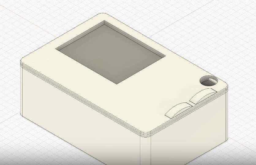
Hero Shot
Main product of this week displayed below

Summary
This week we talked about CAD as a computational tool for generating and optimizing designs, exploring how different representation methods like boundary representation (B-rep) and Constructive Solid Geometry (CSG) allow us to build and modify 3D models. We covered practical operations like fillets, chamfers, and boolean operations, along with the concept of parametric and generative design where you can create models through algorithmic instructions that maintain relationships between elements. We also discussed simulation techniques for structural analysis, interchange formats for moving between different software, and how game engines fit into the computational design ecosystem. Differences between vector and raster images and when to use them in fabrication was talked upon as well.
Notes
Here are my notes from classes and recitations related to this week
Compression
for compression I used a tool I built last week called term-clip mentioned and explained in last weeks documentation
Overview
Though I have had some experinece with 3D and 2D design previosuly they aren’t my strong suit thus this was a week filled with much learning, experimentation and much happy struggle. I started the week out with different ways of 2D skteching. I explored 3 main tools GIMP for Raster, Otto and Inkscaped for Vector.
2D
This section for me was generally about exploring 2D CAD tools and seeing what I could create with them since I had my final project down well enough in my sketches, in my opinion of course. I decided to look at both formats of 2D CAD to see all my options. I first started with Raster images and then moved onto vector.
Raster in GIMP
As an ubuntu user I already had some prior experience in GIMP since it is a great tool to write using a “free-form” way on linux devices. Despite this it was my first time creating any formal images designs in GIMP so it was interesting explroing the interface. This ws what I was met by first a blank white screen ready to be customized

first I filled the screen black since most of my design is more lighter colors closer to white

next I created the outline of the front panel which is what I planned to model modeling in all my exploration of 2D software in this week

then it was onto rounding the corners. First I deleted the sharp corners on the fill I added through the rectangular selection component
 )
)
Then using the pen tool I connected the edges and filled the outside parts of the deletions with black again and had nice filleted corners on my body

Next I added the screen and it’s outline, in a fashion that’d look similar to the E-ink screen I planned on using

Finally I added the buttons and the tittle and my raster demo was done

What I learned
Raster is pixel-based, so it’s good for free-form drawing and anything that feels like painting or photo editing—brushes, gradients, photo retouch. The tradeoff is that clean fillets and cutouts aren’t built-in. To get rounded corners I had to delete the sharp corners on the fill, then use the pen tool to reconnect the edges and fill the gaps with black again. It works, but it’s manual and easy to get slightly wrong. Scaling up or down always risks blur or jaggedness because you’re resampling pixels. For anything that might get resized, sent to a laser cutter, or used as a technical drawing, vector tends to be the better bet. GIMP is still the right tool when the goal is “draw something that looks good” rather than “define precise, scalable geometry.”
Vector in Inkscape
Design in inkscape is a completely new chapter unlike GIMP. Before inscape was only of use to me for preparing PCB’s for mods through its resize page to selection functionality. Now it was time to really use the program for its intended purpose.
Inkscaped like GIMP met me with a blank page

though this time the page was vertical thus using the rotate functionality I made it into a horiontal orientation since my final project is greater in width than length

next I added the main body once again

this time the programm had an easy to use fillet tool so I adjusted the corners easily using that

next I wanted to experiment with shadowing to make my design look more defined so I navigated to the drop shadow command and decided to use it to add a shadow to the back of my design

Also before adding the shadow I added a cyan background to make the shadow look more defined by using the colored surface below is how it looks

Again finally I added the buttons the screen and a shadow to it as well and used the title on the screen and finally the 2D vector of the front face is ready

What I learned
Vector means everything is defined by paths and math, so you can scale up or down without losing sharpness—the same shape, just recalculated. Inkscape has a proper fillet tool, so rounding corners is a couple of clicks instead of the delete-and-fill dance I did in GIMP. Drop shadow and page rotation are right there in the menus, which made the front panel feel more finished without fighting the software. I’d used Inkscape before mainly for “resize page to selection” when prepping PCBs; using it as a real design tool showed how well it fits precise 2D layout—dimensions, alignment, export to SVG or DXF for laser or milling. For anything that needs to stay sharp at any size or feed into a fabrication workflow, this is the 2D workflow that holds up.
Vector in Otto
Now it was onto Otto. If you weren’t at ACM SCF 25’ you might be asking what Otto is. For those who don’t know it is a multimodal parametric design environment built by the IdeaLab FabLab, us, which I and my mentor Mr. Yalçın lead the development off. Otto is a tool usually used for preparing parametric assemblies to be cut from the laser cutter and later assembled I wanted to see how it would be designing the front panel from it. It was particularly valuable since it was the first dip in parametric design of my fabacademy journey. To sum it up this was more of a self experiment on a more fabrication focused product for a more designed based job.
Below is the interface greeting me once again blank white as others.

I again started out with the rectangle for the body

Then came in the buttons

Finally I added the rest of the cut outs and modified the names accordingly

Next I added the parameters for the parametric experiment through the block code interface

This was the final look after all the changes

After getting all this design done I exported the design as an svg and the parametric vector experiment was done. Below is the export.

Below is the final code for those who want to try out, the link to the page is in my about me section:
//Otto by the IdeaLab Fablab

param body_x  7
param body_y  18
param body_width  596
param body_height  314

param button_rotation  89.3259631020155
param button_radiusX  40
param button_radiusY  11
param buttons_x  body_x + 265
param button1_offset  47
param button1_y  body_y + button1_offset
param button_spacing  106
param button2_y  button1_y - button_spacing

param screen_offset_x  121
param screen_x  body_x - screen_offset_x
param screen_y  body_y + 65
param screen_width  288
param screen_height  144

param button3_offset_x  207
param button3_offset_y  117
param button3_x  body_x + button3_offset_x
param button3_y  body_y + button3_offset_y
param button3_radius  27.46515178284885

shape rectangle body {
    position: [body_x, body_y]
    width: body_width
    height: body_height
    fill: false
}

shape ellipse button1 {
    rotation: button_rotation
    position: [buttons_x, button1_y]
    radiusX: button_radiusX
    radiusY: button_radiusY
    fill: false
}

shape ellipse button2 {
    rotation: button_rotation
    position: [buttons_x, button2_y]
    radiusX: button_radiusX
    radiusY: button_radiusY
    fill: false
}

shape rectangle screen {
    position: [screen_x, screen_y]
    width: screen_width
    height: screen_height
    fill: false
}

shape circle button3 {
    position: [button3_x, button3_y]
    radius: button3_radius
    fill: false
}

difference a {
    add body
    add button1
    add button2
    add screen
    add button3
}
What I learned
Otto is a good tool to use.)
3D
Now it was onto 3D where I tried different workflows to create my model, usually parametrically. I started out from the most familiar one to me Fusion360 and moved beyond.
Fusion360
Before I had had some experience with 3D modeling on the surface level particularly engaging with the algorithmic nature of parametric designing though I had not yet designed a full scale parametric product. This was going to be the first time I was going to create a fully fabrication ready, multi-part, parametric model. Below is the full video showcasing the design.
Below are the parameters used to design the model:
| Parameter | Unit | Formula/Value | Value |
|---|---|---|---|
| length | mm | 120 mm | 120.00 |
| width | mm | length * 2 / 3 | 80.00 |
| fillet_main_rect | mm | length / 24 | 5.00 |
| z_rect | mm | length / 3 | 40.00 |
| fillet_on_box_n_l… | mm | 0.5 mm | 0.50 |
| sw | mm | 45.81 mm | 45.81 |
| sh | mm | 57.30 mm | 57.30 |
| sd | mm | 2 mm | 2.00 |
| open_button_dia | mm | 12 mm | 12.00 |
| cap_extrudes | mm | 2 mm | 2.00 |
| plat_thickness | mm | 5 mm | 5.00 |
| l_button_l | mm | 20 mm | 20.00 |
| but_height | mm | 4.0184454117 mm | 4.018 |
| but_thick | mm | 6.00 mm | 6.00 |
| but_norm_cap | mm | 3.4 mm | 3.40 |
| but_embedd_extr… | mm | 1.75 mm | 1.75 |
| camera_size | mm | 9 mm | 9.00 |
Design process
I started out by creating the base of the design using a simple rectangle with 5 mm filleted corners. This rounded profile helps avoid sharp edges and gives the device a more polished, ergonomic shape right from the beginning.

After establishing the base profile, I extruded the sketch upward to create the main body. To prepare space for the internal components, I then hollowed out the interior of the solid. This created the cavity that will eventually house the electronics and screen. Once the shell thickness was established, I projected the outline of the original sketch onto the top face of the box. I did this because I wanted to construct a separate removable lid, and the projected geometry ensured that the lid would match the box footprint exactly.

Using this projection, I proceeded to build the lid. I extruded the outer contour of the sketch upward, forming the upper surface of the lid. Then, using the inner contour, I extruded downward by the same amount, creating the inner lip that fits into the box and keeps the lid aligned during assembly. This interlocking structure ensures that the lid sits securely and reduces lateral movement. After forming the lid, I added fillets both to the outer edges and to the inner top edges of the box, smoothing the contact surfaces for a cleaner appearance and a more comfortable fit.

Since I planned to make a device where a primary functionality was being an e-reader I was going to use an E-ink screen and decided on using the 2.7 inch screen shown below. According to the given dimensions, displayed below, I created a cut out on the lid so the user could view the screen.

After creating the opening for the screen, I projected the cutout’s sketch onto the inner surface of the lid. Using this projection as a reference, I modeled a support platform inside the enclosure. This platform acts as a stable seat where the e-ink screen can rest securely, preventing it from shifting or falling deeper into the body. It also ensures the screen aligns perfectly with the front-facing window, keeping the display flush with the lid for a clean, professional appearance.

Once the display support was in place, I moved on to the interaction elements of the device. I added the necessary circular and rectangular holes for the up and down navigation buttons, carefully positioning them so the user could comfortably operate the device with one hand. To complement these openings, I designed matching button caps that fit into the holes with a small clearance, allowing smooth vertical travel while maintaining the overall aesthetic of the front face. With these components added, the design began to resemble the final form of the device.

After completing the primary chassis and ensuring all interface elements were integrated, I decided to expand the functionality further by including a camera cutout on the back of the enclosure. This addition would allow the device to support basic imaging or scanning features. Using the exact mechanical dimensions of the camera module shown below, I created a precise opening that accommodates the lens while leaving enough surrounding material for structural strength and mounting stability.

What I learned
Fusion’s parametric side is the user parameters table—you put dimensions and formulas in one place (length, width, fillet_main_rect, etc.) and the whole model updates. Change one value and extrusions, fillets, and cutouts all follow. Projecting a sketch onto a face (e.g. the top of the box) gave me a lid footprint that matched the body exactly; that way the lid and body are driven by the same geometry and you don’t get “almost fits” when you actually assemble. Fillets, extrusions, and booleans all map cleanly to how parts get machined or printed—extrude the outer contour for the lid, extrude the inner contour down for the lip, add fillets where things meet. The timeline can feel dense at first, but once you’re used to it, it’s a solid path from idea to fabrication-ready geometry, and the param table makes it easy to try “what if it were 10 mm longer?” without rebuilding from scratch.
Fabrication
After completing the Fusion 360 model I decided I was satisfied with it to a level that I was ready to fabricate it. The fastest and easiest way to do that at this stage was using the 3D printer so I fabricated it out of the printer and it came out as expected. A particular feedback I got from people who saw the design was that it had a nice finish to it making me further satisfied with the color choice.
Below is an image post fabrication and the video for the lid test
Post Fab Hero Shot

Lid Test
OpenSCAD
As a programmer originally it is only natural I move to SCAD after Fusion. Though OpenSCAD has been great for modeling mathematical forms and generative algorithmic design, I approached this as a full CAD exercise where I designed a complete enclosure parametrically through code. It was like finding novelty in a familiar setting and medium of interaction.
Core Parameters
All dimensions are defined at the beginning of the file as variables, making the design fully configurable:
| Parameter | Value | Purpose |
|---|---|---|
| box_length | 120 mm | Overall enclosure length |
| box_height | 40 mm | Overall enclosure height |
| box_width | 80 mm | Overall enclosure width |
| wall | 3 mm | Shell wall thickness |
| corner_r | 2.5 mm | Outer corner radius |
| inner_corner_r | 1.5 mm | Inner wall corner radius |
| screen_width | 55 mm | E-ink display opening width |
| screen_height | 35 mm | E-ink display opening height |
| button_d | 12 mm | Navigation button diameter |
| camera_size | 10 mm | Camera lens opening size |
Modular Design Structure
The model is organized into reusable modules:
Geometry Primitives:
rounded_box()- Creates rounded boxes using hull() and spheres for organic cornersrounded_box_flat_bottom()- Variant with a flat bottom face for the main enclosure
Functional Components:
box()- Main enclosure with hollowed interior, camera opening, and screw bosseslid()- Removable top with screen cutout, button openings, and countersunk screw holespcb_standoffs()- Four mounting posts to support and position the internal PCBinternal_ribs()- Structural reinforcement to prevent flex
Assembly Views:
assembly()- Colored visualization showing box and lid in their final orientationprint_layout()- Optimized arrangement for 3D printingbox_complete()andlid_complete()- Individual part exports
Key Design Features
Rounded Corners: Using the hull() function with positioned spheres creates smooth corner radii on both outer and inner surfaces, improving both aesthetics and printability.
Interlocking Lid: The lid features a lip that extends downward (lip_inset and lip_height) which fits into a matching groove on the box body, ensuring the lid stays centered and aligned during assembly.
Screen Integration: The E-ink display opening is precisely dimensioned based on the actual screen specifications (2.7 inch), positioned in the upper right of the lid for optimal viewing while maintaining structural support.
Button Access: Two pill-shaped buttons (navigation buttons) and one circular button are positioned through the lid face, with the shapes extending through the full lid thickness for reliable operation.
Review and Final Product
Though it is interesting and fun to design in SCAD due to the nature of my final project SCAD didn’t prove to be exactly efficient for the task. Despite this I followed through and created a mock up of my project that can be moved below.

What I learned
In OpenSCAD the code is the single source of truth—variables at the top (box_length, wall, corner_r, etc.) and modules for repeated bits (rounded_box, lid, pcb_standoffs) keep everything consistent and easy to change. hull() around spheres gives you rounded boxes without a fillet tool; difference() is your boolean cut. You build the shape from primitives and operations, which fits how you think about “hollow box with holes and a lip.” It’s strong when you want algorithmic or batch variants (e.g. “every size from 80 to 120 mm” or “generate a grid of standoffs”) or when you’re comfortable thinking in code and want version control and reuse. For one-off organic or sculpted forms it’s slower than a direct modeler—no pushing vertices, no sculpt brush. For enclosures and mechanical parts with clear dimensions and relationships, the tradeoff is clear: code gives you repeatability and clarity, and the output (STL) is just as usable as Fusion or anything else for printing or CAM.
Blender
Blender was a unique experience since unlike tools up until now it was more explore than design. This blender phase was made up of two parts one was lid animation which was just a simple way to learn the basics of the program and make the lid fall onto the body, a basic visulization of how the device would close and the second part was more of a exploration I would like to call pingu.
Lid animation
I was once again greeted by a cad programs blank interface though it was a dark grey this time instead of the usual white, a welcome change.

Next I imported my model by exporting the lid and box components seperately as stl’s from Fusion 360

After this I realized I knew nothing about Blender and after a short youtube search found this tutorial suitable
though it worked well I decided to add some color to the scene since it looked to boring. I made Pockety it’s intended white meanwhile I added a wood background for a better look

pingu
My project wouldn’t see much merit being re-design in blender as it doesn’t have surfaces to be sculpted or many parts to be animated, but blender is a tool I want to further explore thus I decided to create a simple animation. A penguin walking backwards was what I settled on. Before starting I followed the tutorails below
Also I saw great benefit from one of the documented workshops, particularly the one tittled MCP which was about setting up an MCP server to allow claude to ineract with Blender. It was particularly helpful to quickly add textures.
I first sculpted this penguin figure

Then I added this snowy scene using PolyHaven textures and added a particle emitter to send down snow particles, final scene pre-animation

Finally all was ready for the penguin to walk and the animation below was what came alive.
What I learned
Bringing in STLs from Fusion (or any CAD) works fine—export the lid and box separately, import into Blender, and you’re in a different world: meshes, materials, animation. Keyframes and a bit of physics got the lid-on-box animation without hand-animating every frame; that’s the kind of thing that’s tedious in CAD but natural in Blender. For the penguin side, sculpting plus textures and particle systems (snow) showed how Blender is built for presentation and “look”—organic forms, lighting, motion—rather than fabrication dimensions. You’re not driving a parametric table; you’re pushing geometry and painting surfaces. Using an MCP server so an AI could drive Blender was surprisingly useful for quick texture and scene setup without digging through every menu; it’s a different way of working that fits “I want it to look like this” when you’re not yet a Blender power user.
Wrap up
Overall, this was a productive week. I now have a solid sense of 2D and 3D CAD workflows—raster vs vector, parametric vs direct modeling, and when to reach for which tool. The setup process taught me a lot about how different representation methods (B-rep, CSG, code, timelines) map to fabrication and to “look and feel,” and I can carry that through the rest of Fab Academy.