Week 15: System Integration
Planted May 11, 2026

Overview
Week 15 is where separate pieces from earlier weeks stop living in isolation and start behaving as one system. For me, this week is about wiring together the parts that matter for my final project: electronics, firmware, mechanical fit, and any user-facing pieces, then proving the whole loop works reliably. Below is a detailed explanation of the assembly.
System Integration
below our my components
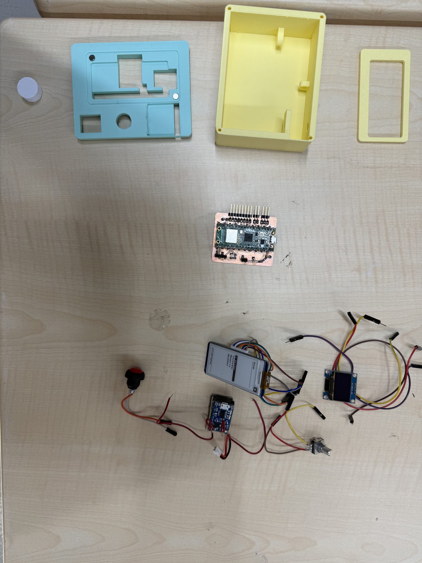
the cover for the screen, the top of the device, the body of the device, the shaft for the encoder, the PCB, a 2.13 inch e ink screen, a 0.96 inch oled, a push button, a 350 mah 1s lipo, a lipo charging module and a lipo battery charging module.
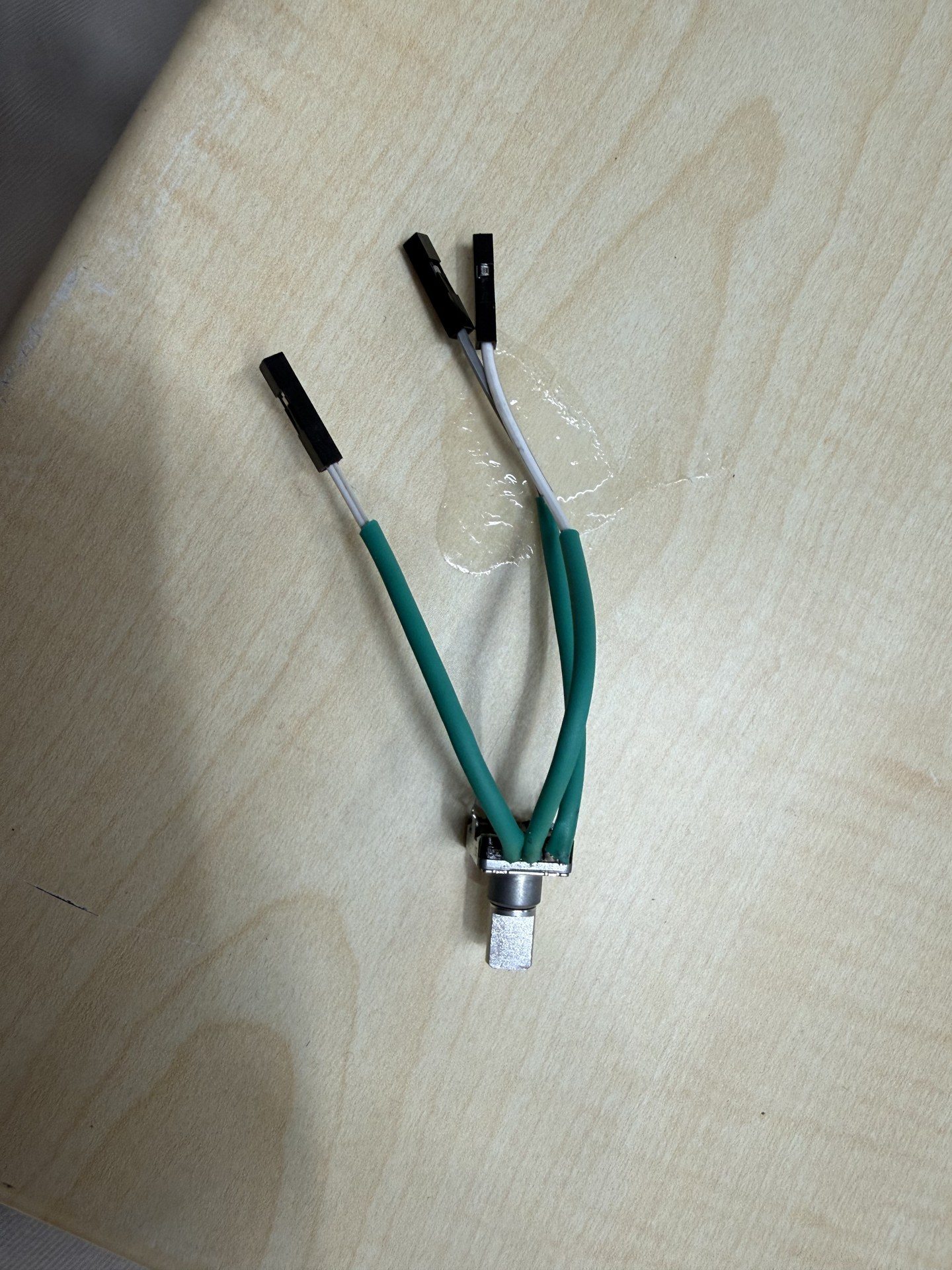
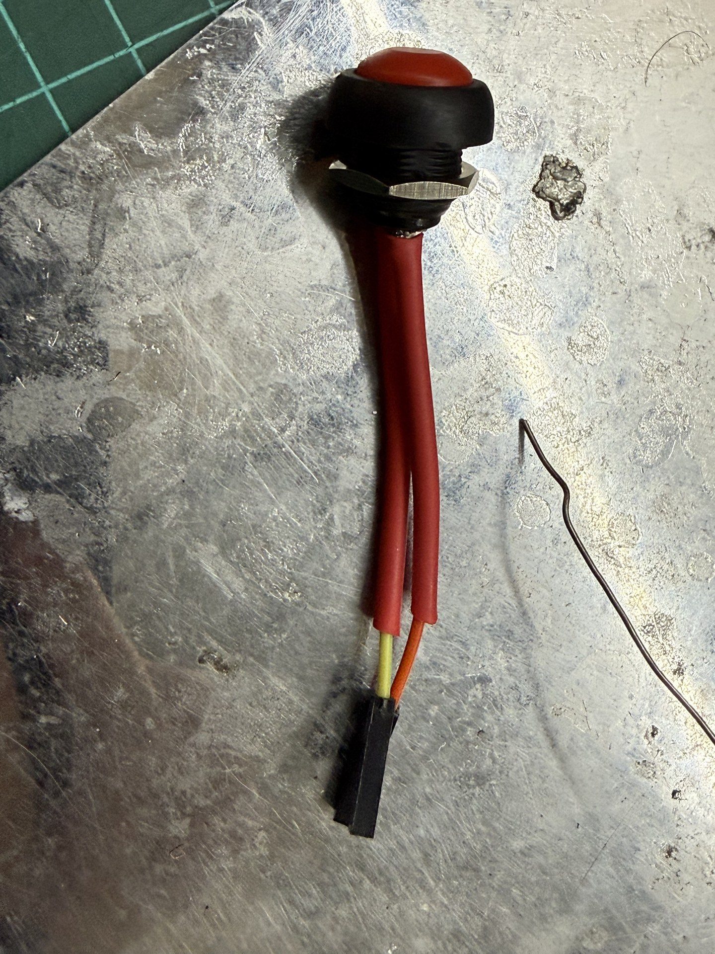
first I soldered cables to the magnetic encoders terminals and applied heaqt shrinks to the said areas for safety
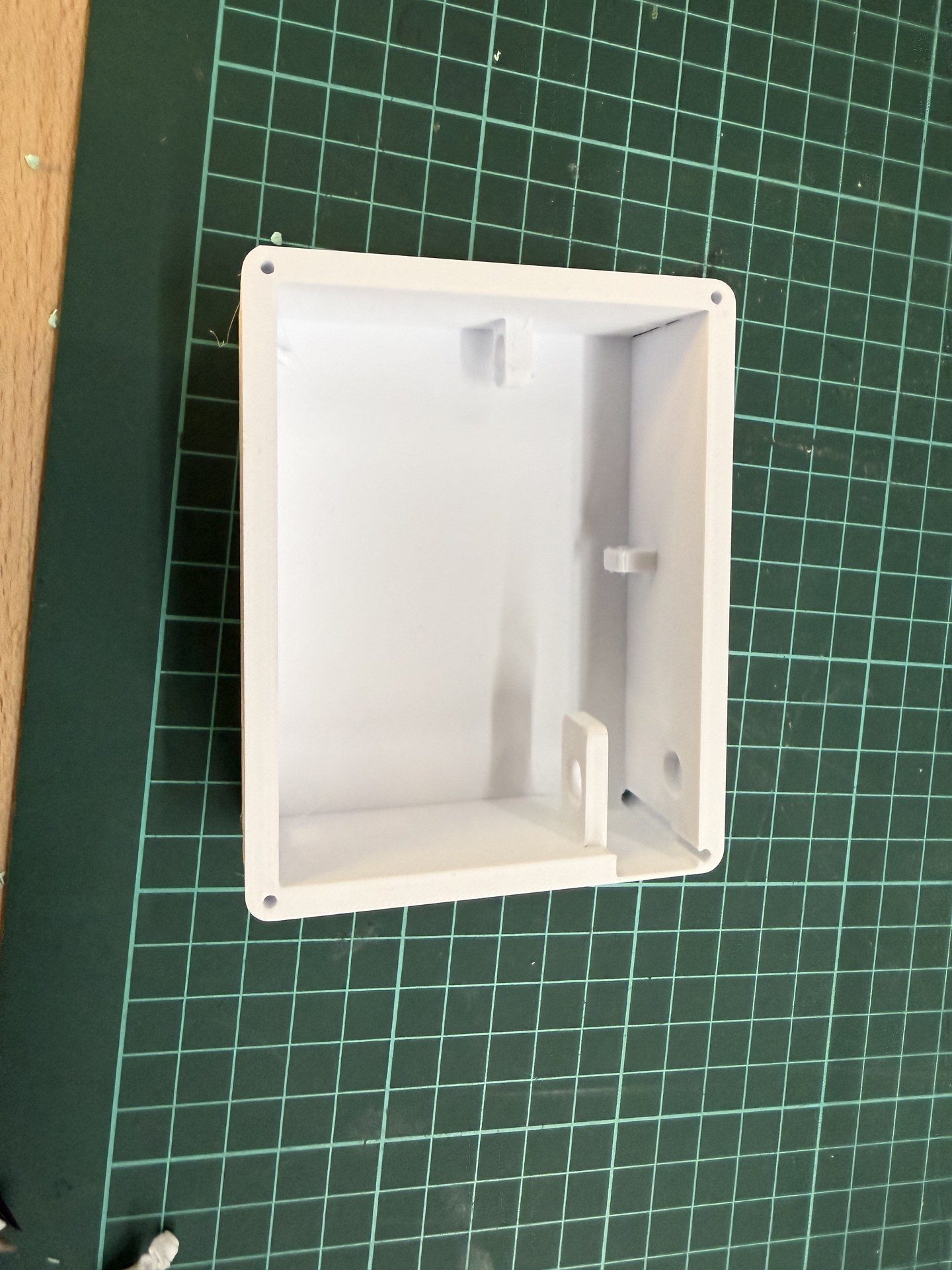
next I fetched the body
then I inserted the encoder into the designated slot and the pushed it into the shaft
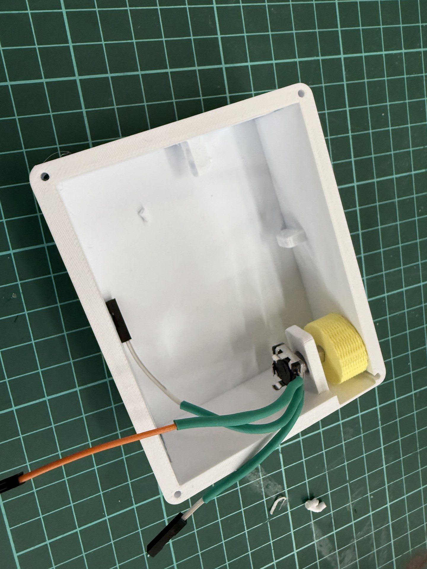
then using a screwdriver I pressed the larger shaft into the encoder
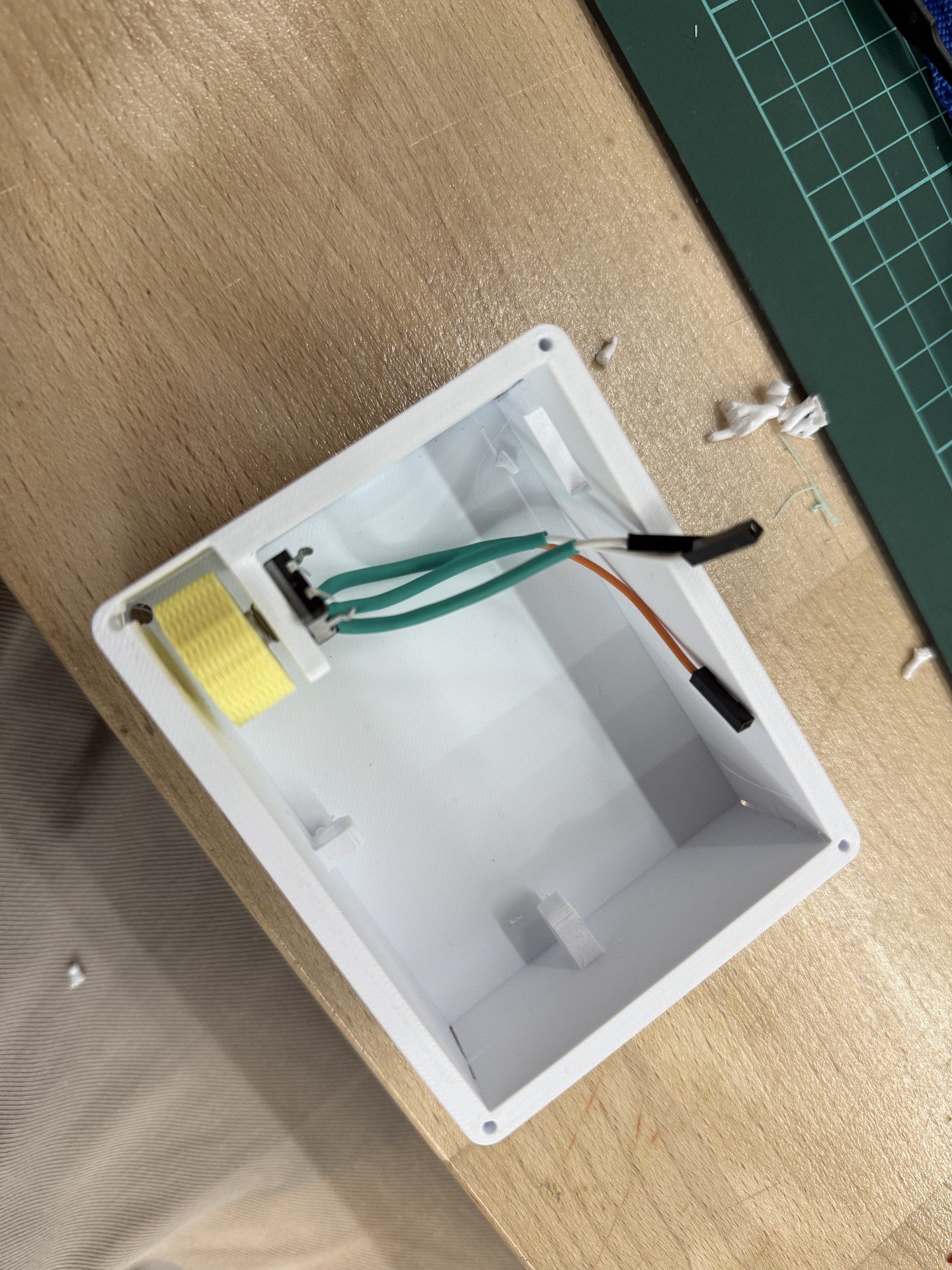
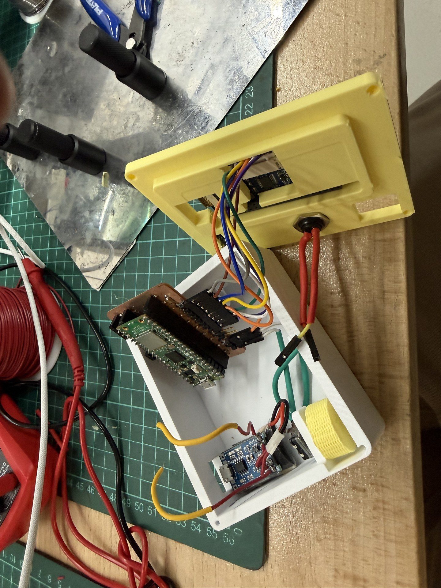
Then for cable management I passed the cables through the designated hole to keep them contained
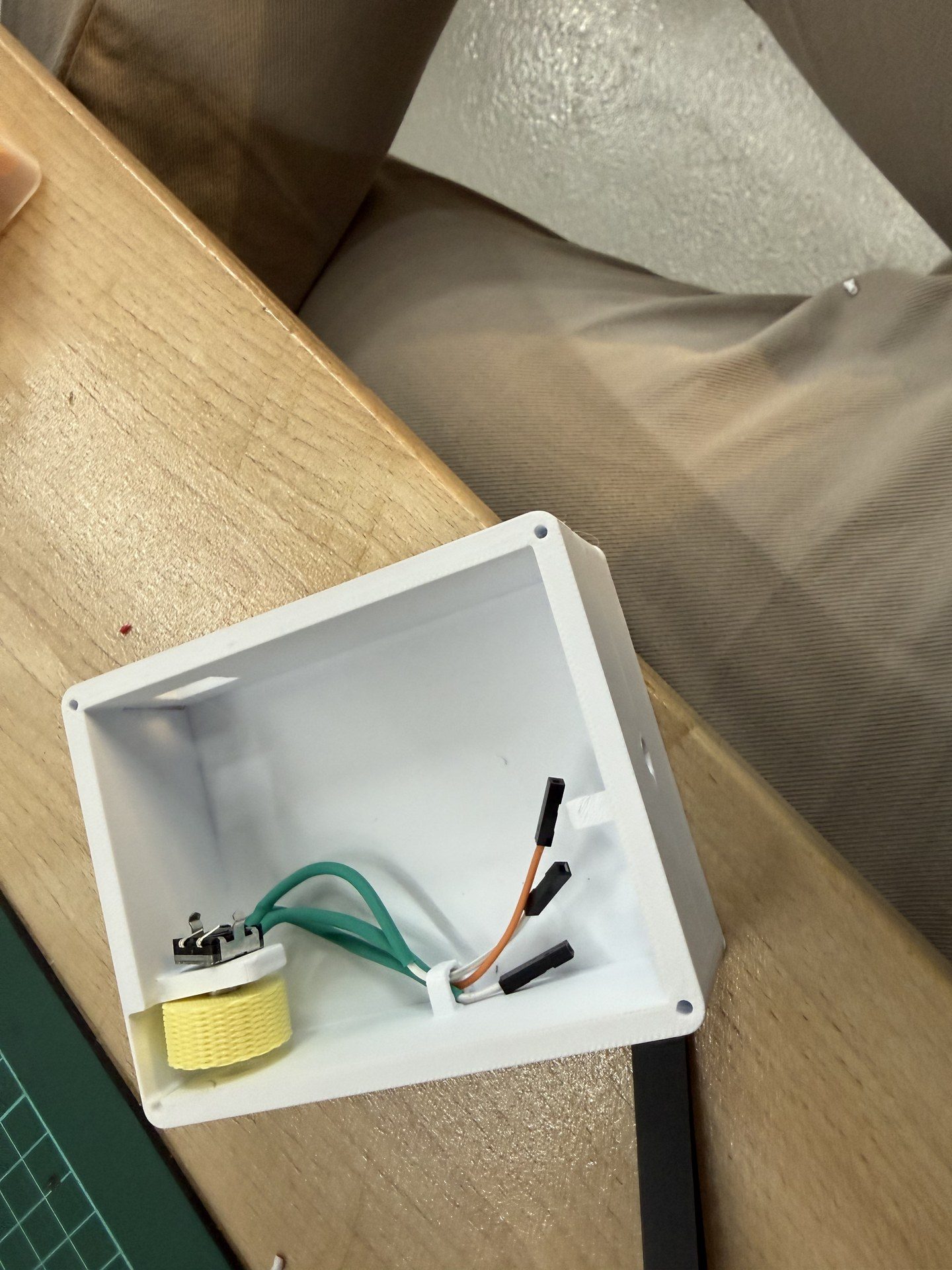
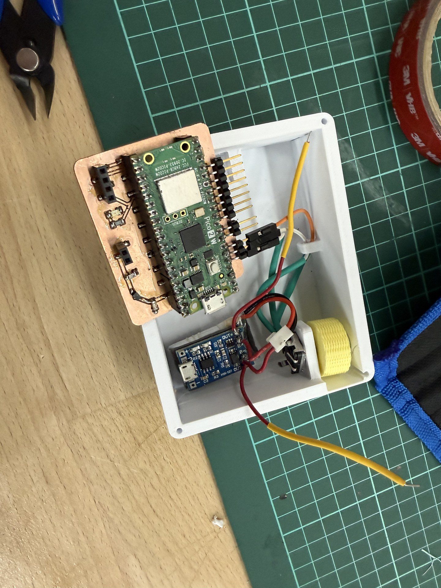
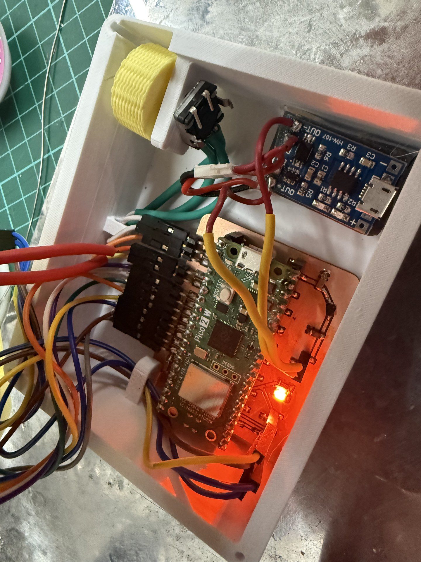
next I placed the PCB for connecting the cables
connection done
then I added the two story LiPo charging module and the lipo connected in a unibody via double sided tape
next I soldered cables onto the terminals on the buttons and then secured them with heat shrink
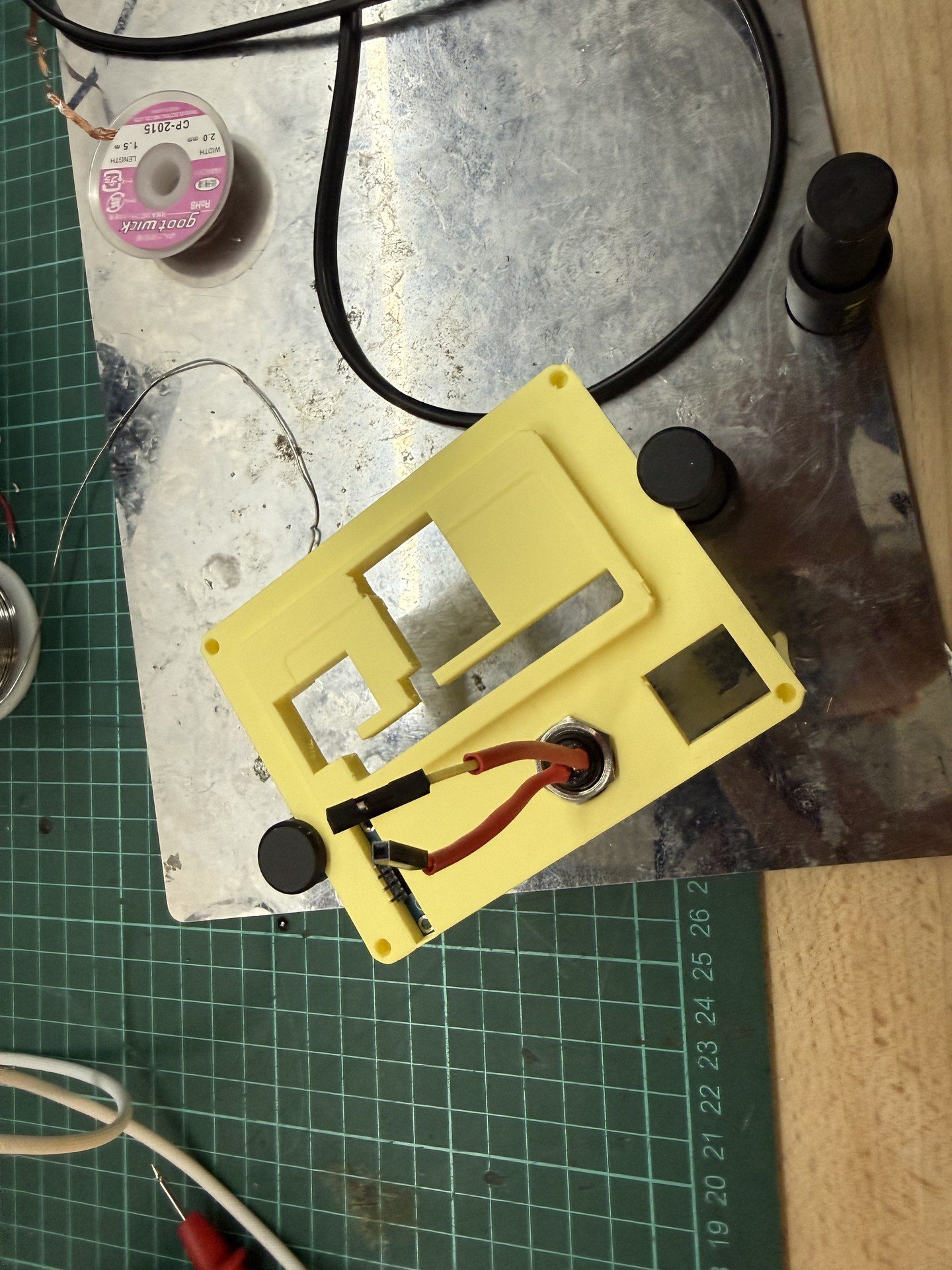
then I secured the button onto the top of the body via the proprietary nut of the button
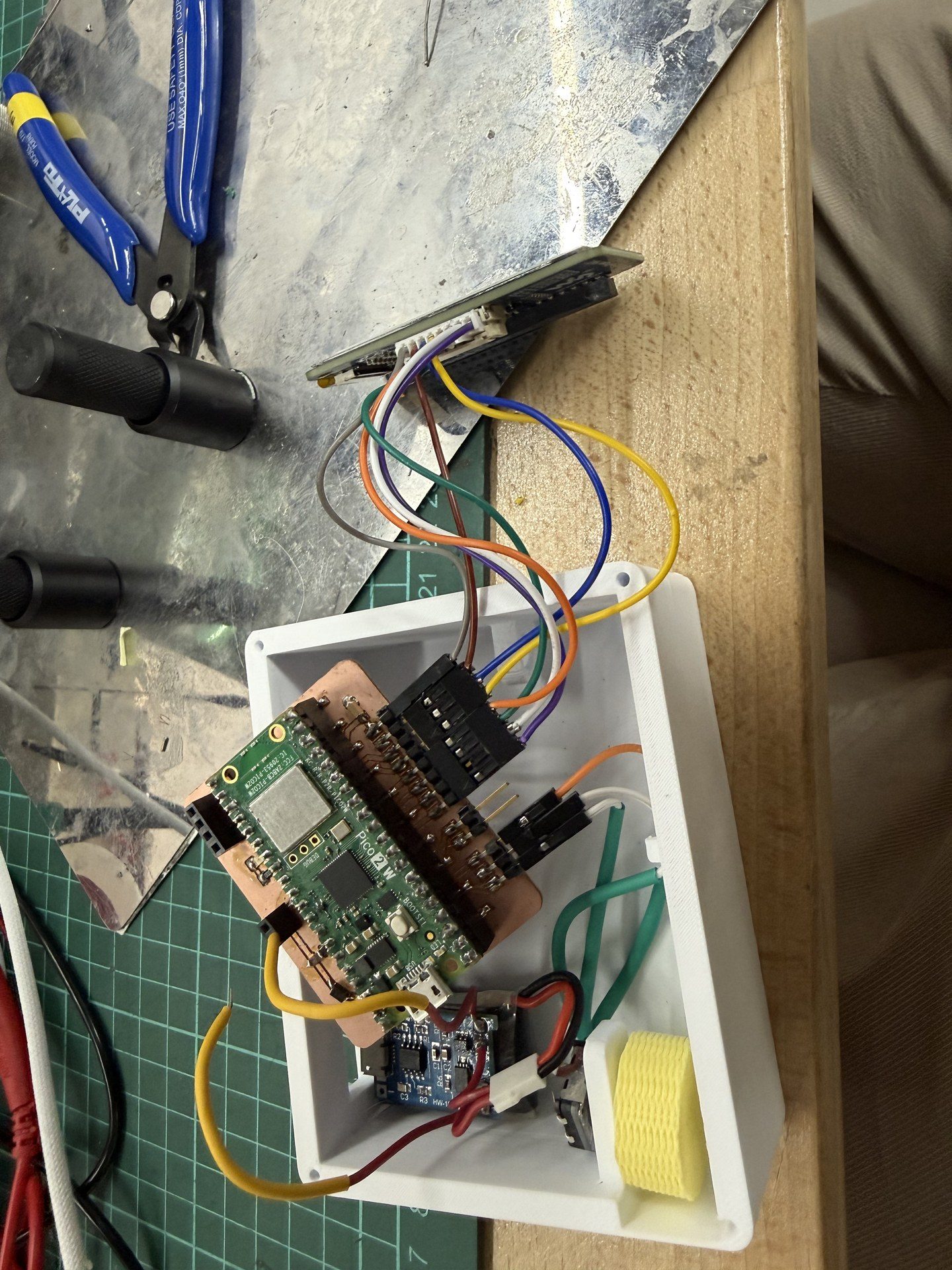
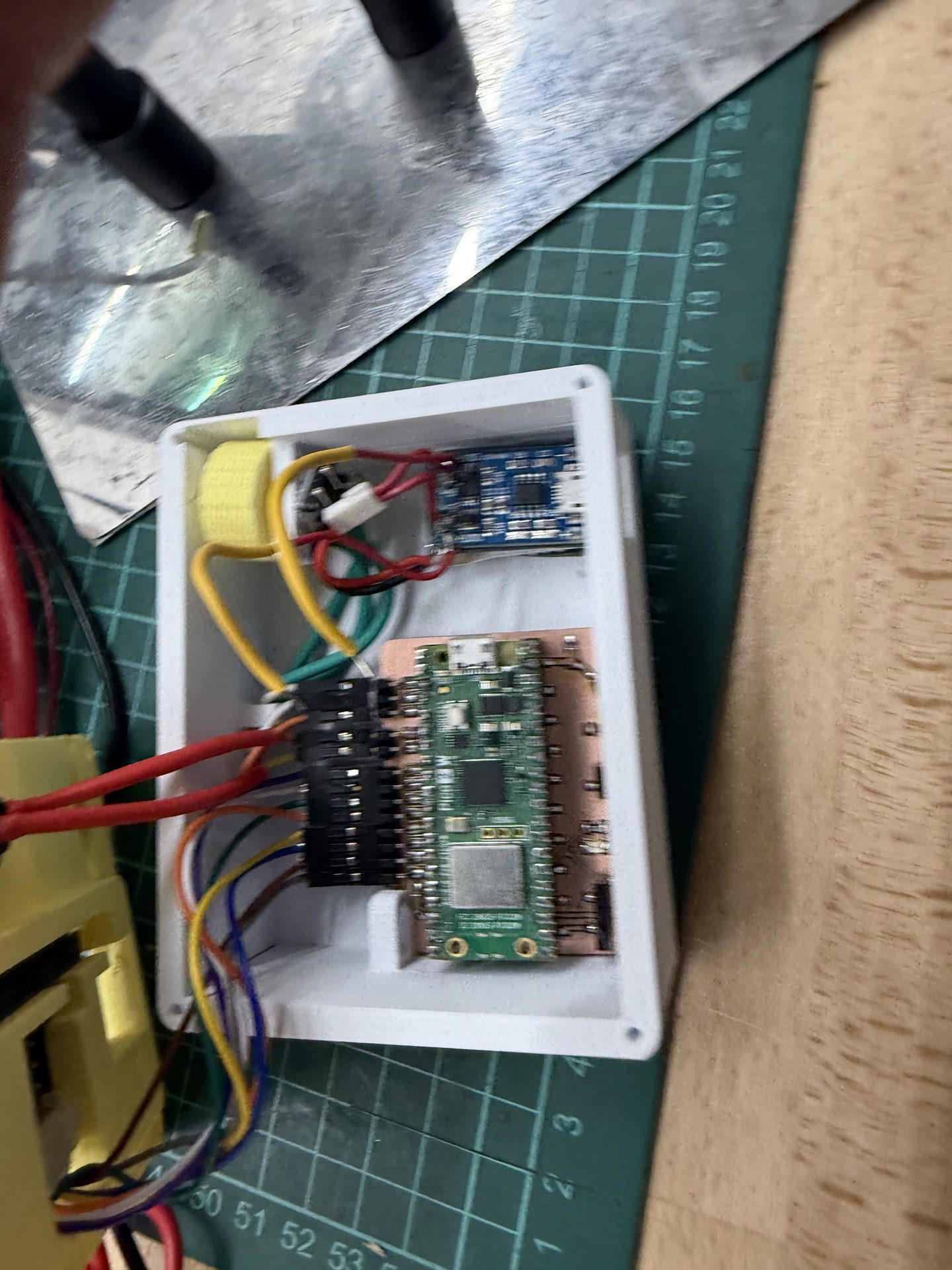
next before innserting the top I connected the cables of the screens to the pico
then I inserted the e-ink to the cap and brought the cap into the picture
next I established the buttons connections
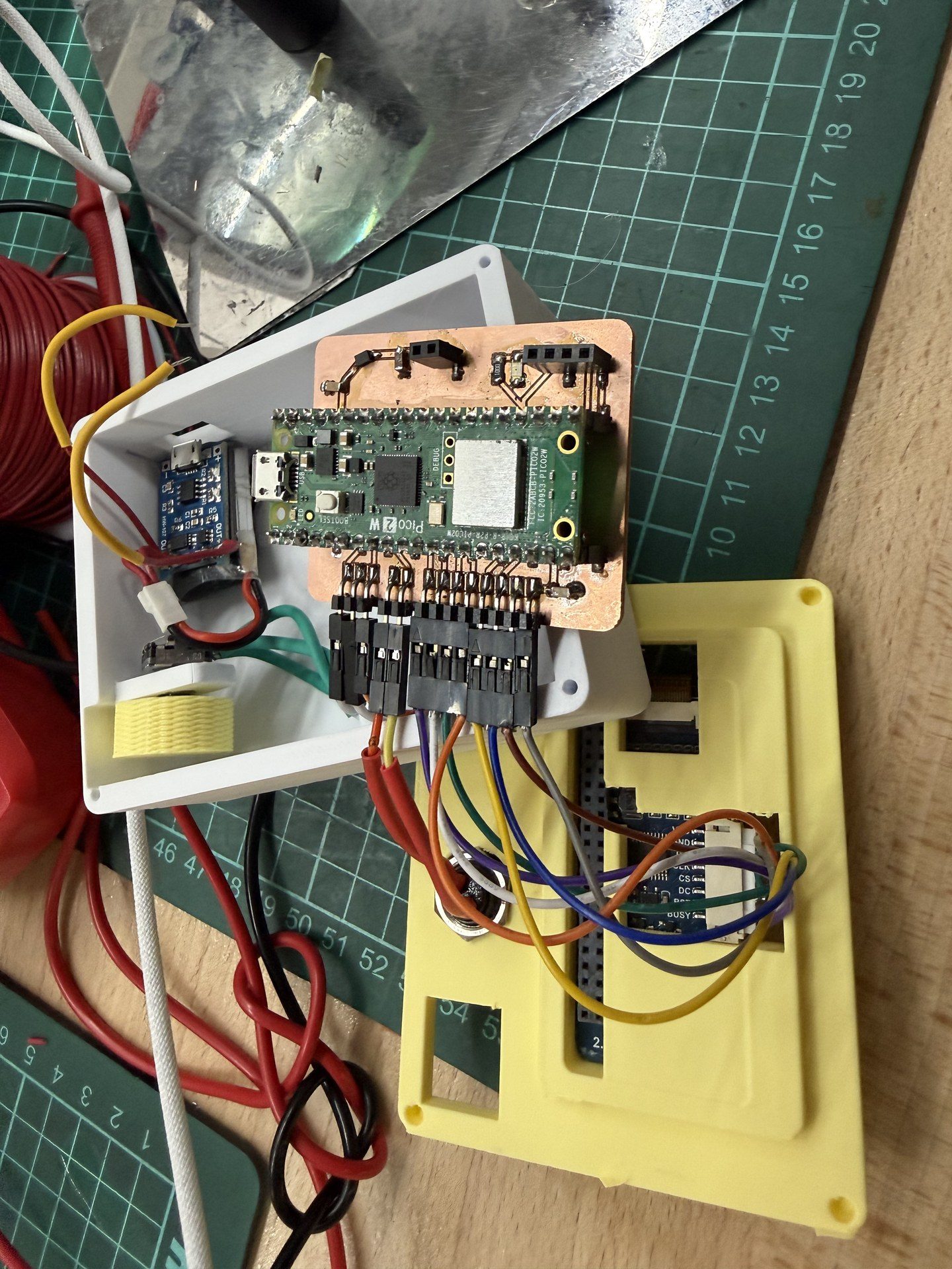
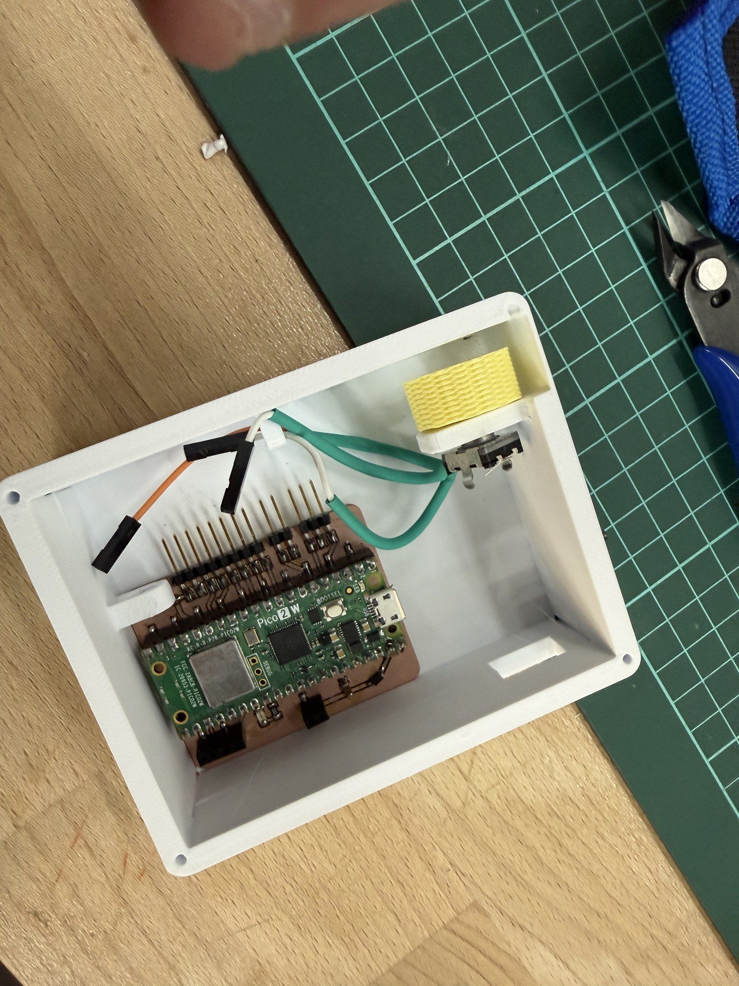
Then I stabilized the pcb on the board using the oled guide rails as the holder
Then I placed the oled in the designated place
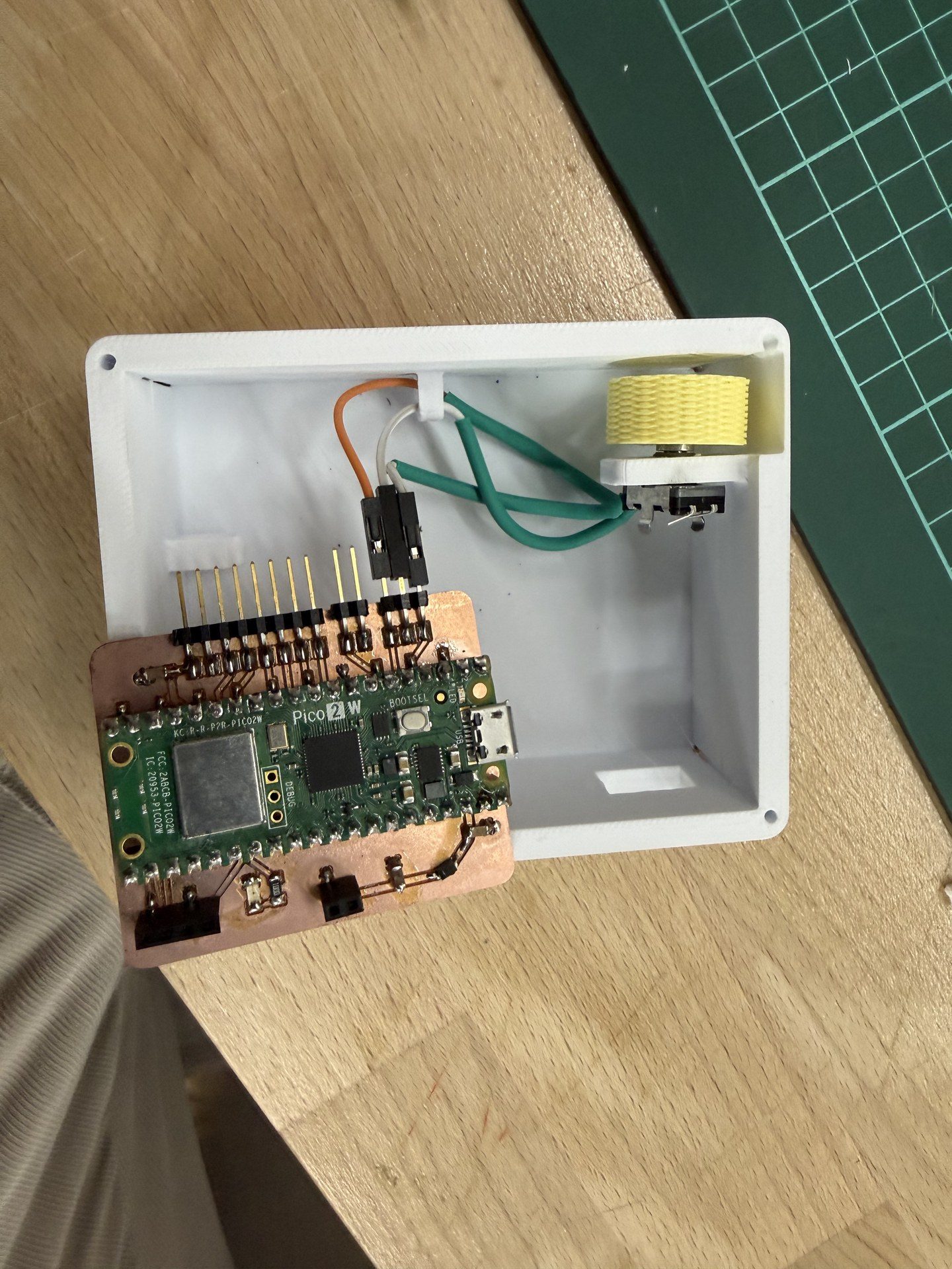
next I made the connections to the pcb making the cables pass through the guide rails once again. Also I connected the power cables from the charging module to the designated slots to power it up
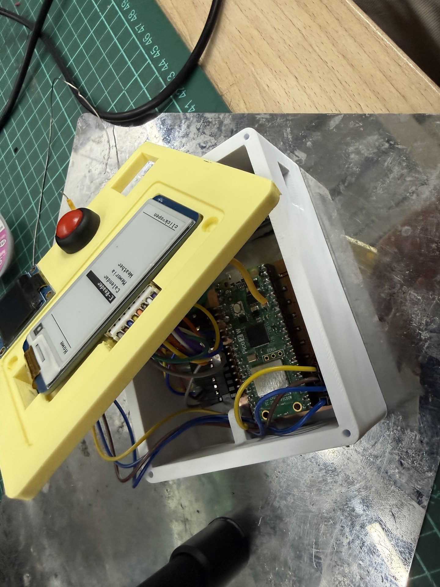
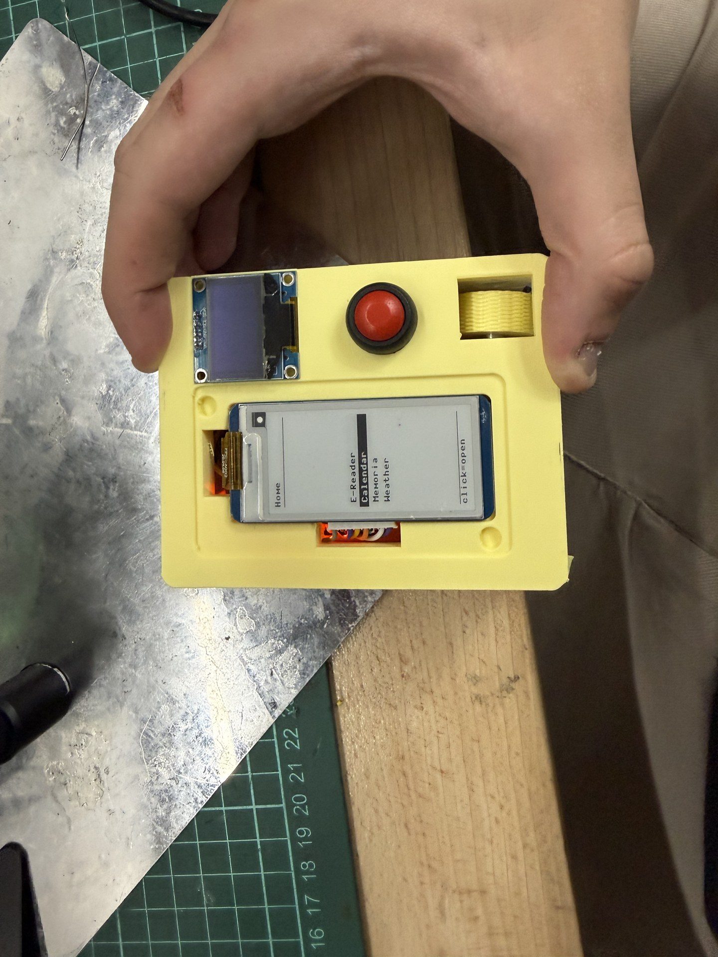
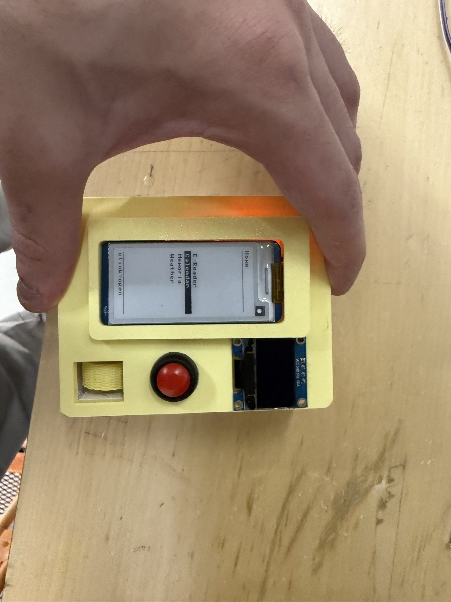
Pre close up hero shot
next I press fitted the magnets onto the top
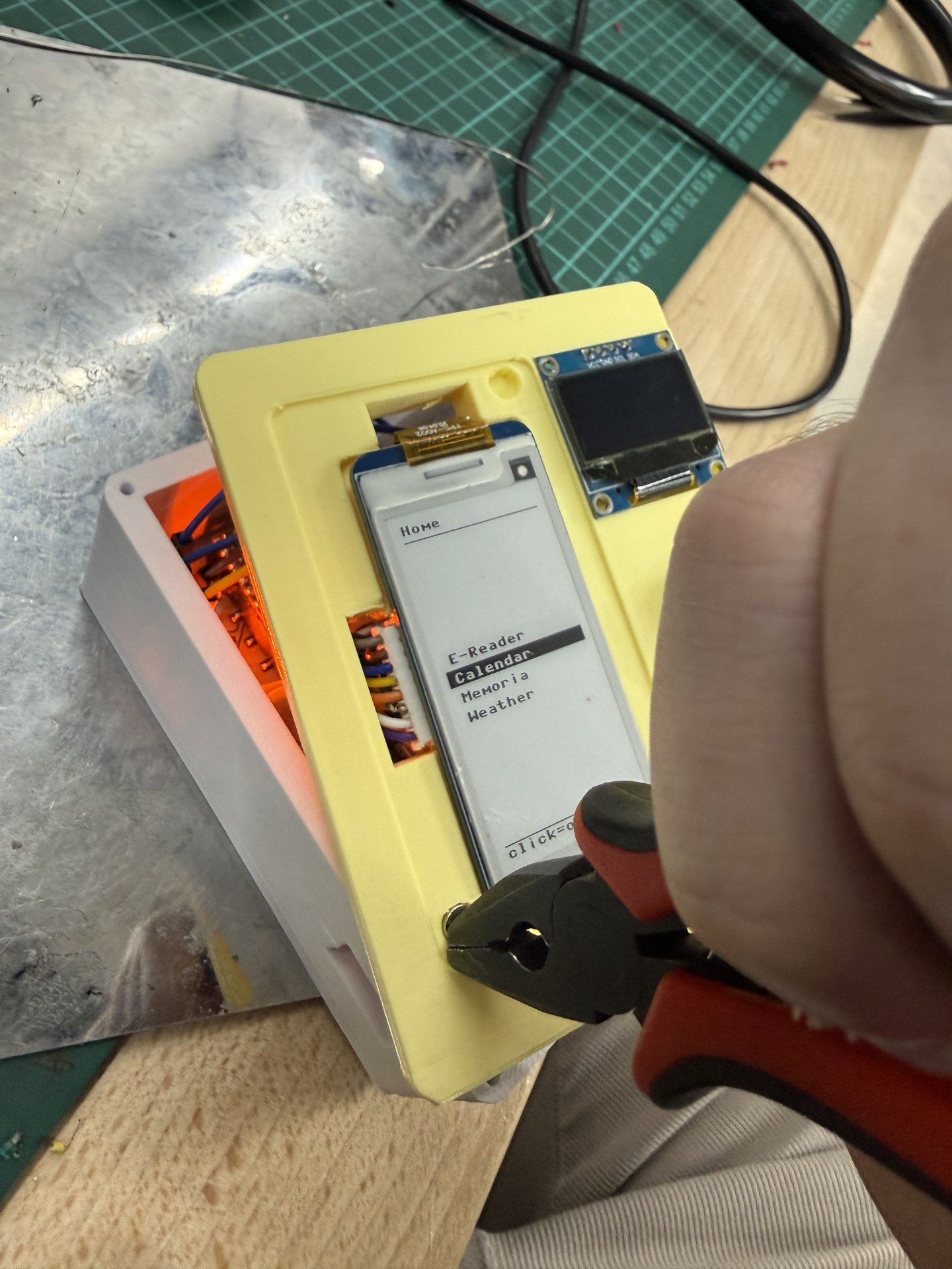
then I made the magnetic connection for the e-ink screen cap and the top*
Then I added the screws to hold the top and body. Note that brass inserts were inserted to the top so screws could be secured there
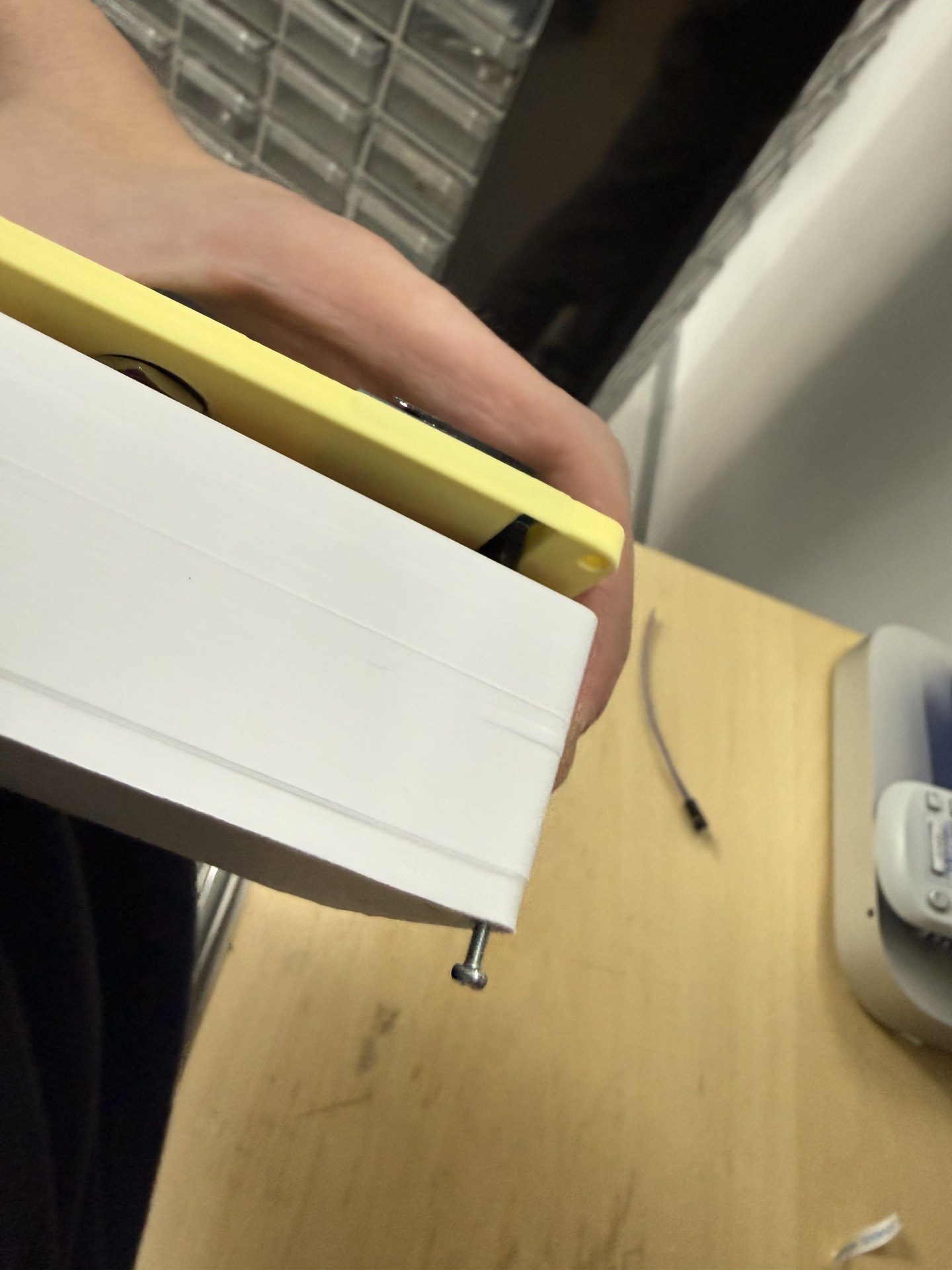
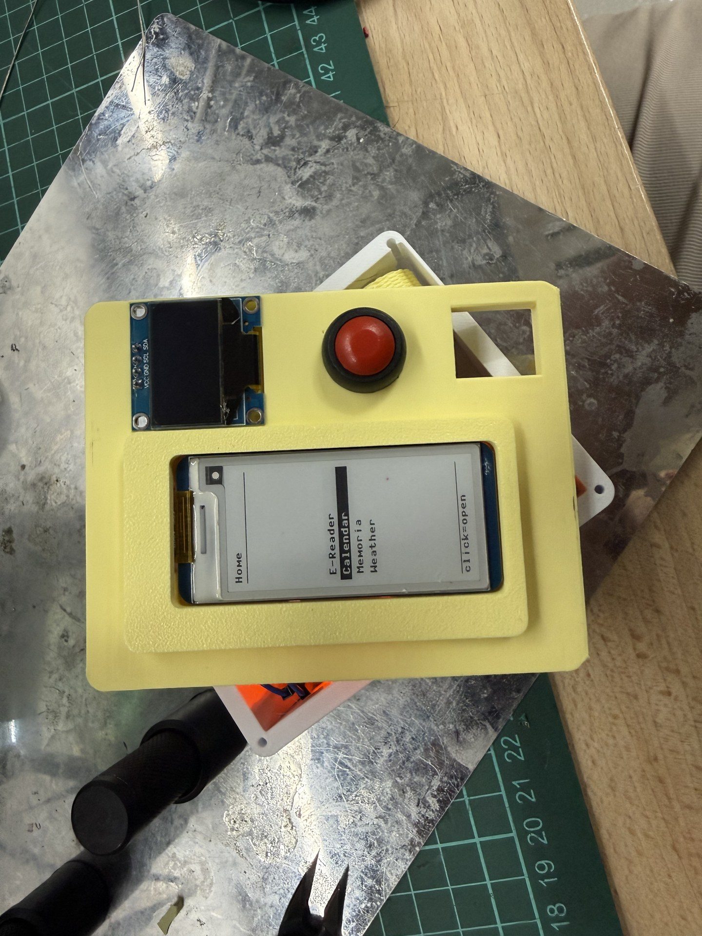
final shot of the system integration
Additional notes
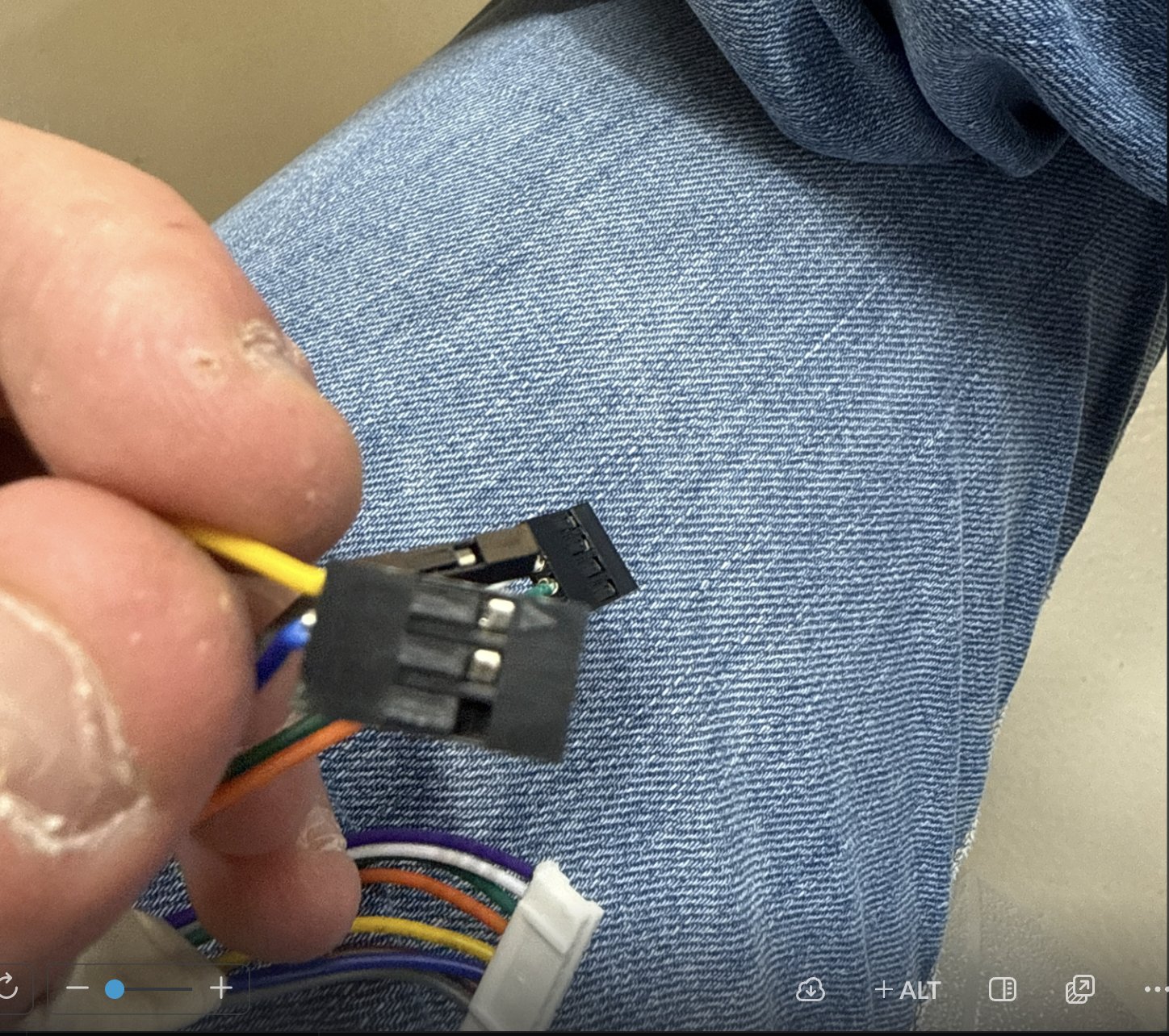
I recrimped the cables for the screen as they were too long for the small form factor I was aming for. Since I am terrible with my hands, except my precise soldering, it took 12 hours for 8 cables
## Detailed Descriptions and Notes
PCB BOM
| Part Name | Quantity |
|---|---|
| Raspi Pico 2 W | 1 |
| LED_1206 Orange | 2 |
| C_1206 0.1 uF | 2 |
| R_1206 100 ohms | 1 |
| C_1206 10 uF | 1 |
| Conn_PinHeader 2.54mm | 13 |
| 5 Pos Vertical SMD Socket | 8 |
| 4 Pos Vertical SMD Socket | 1 |
| 3 Pos Vertical SMD Socket | 1 |
| 2 Pos Vertical SMD Socket | 1 |
General BOM
| Part Name | Quantity |
|---|---|
| PCB | 1 |
| ALPS EC11 Magnetic Encoder | 1 |
| IC184 red push button | 1 |
| Waveshare 2.13 inch E-ink screen | 1 |
| 0.96 inch ssd1306 OLED screen | 1 |
| 1S 3.7V 350 mah lipo battery | 1 |
| TP4056 charging module | 1 |
Device Power Consumption
Component Power Estimates
| Component | Estimated Current Consumption |
|---|---|
| Raspi Pico 2 W | 150mA (max with Wi-Fi active) |
| 2 × LED_1206 Orange | 40mA total |
| Waveshare 2.13" E-ink Display | 26mA (refresh peak) |
| 0.96" SSD1306 OLED Display | 25mA |
| ALPS EC11 Magnetic Encoder | Negligible (<5mA) |
| IC184 Push Button | Negligible |
| Passive Components (capacitors/resistors/connectors) | Negligible |
Total Estimated Power Consumption
Maximum estimated system current:
[ 150mA + 40mA + 26mA + 25mA \approx 241mA ]
Estimated maximum current consumption is approximately 240–250mA.
Battery Runtime Estimation
The system is powered using a 1S 3.7V 350mAh LiPo battery.
Estimated runtime:
[ \text{Runtime} = \frac{350mAh}{241mA} \approx 1.45 \text{ hours} ]
Expected practical runtime is approximately:
- 1–1.3 hours under heavy usage
- Longer under intermittent display refresh and reduced Wi-Fi activity
This reduction is due to:
- DC-DC conversion losses
- Wi-Fi transmission spikes
- OLED brightness variation
- Battery discharge characteristics
Power Supply and Charging
| Power Source | Purpose |
|---|---|
| 1S 3.7V 350mAh LiPo Battery | Main portable power source |
| TP4056 Charging Module | Battery charging and protection |
The TP4056 module provides:
- LiPo charging control
- Overcharge protection
- Over-discharge protection (if protection version is used)
Voltage Regulation
The LiPo battery voltage varies approximately between:
- 4.2V (fully charged)
- 3.0V (discharged)
The Raspi Pico 2 W internally regulates input voltage for its 3.3V logic operation. External peripherals requiring stable voltage levels are powered through regulated supply rails as needed.
Power Supply Compliance Notes
- The total estimated current remains within the capability of a standard 350mAh LiPo battery for short-duration portable operation.
- Proper decoupling capacitors (0.1uF and 10uF capacitors) are included to stabilize voltage during Wi-Fi activity and display updates.
- USB charging current through the TP4056 module should be limited according to battery specifications.
- Care should be taken to avoid simultaneously driving maximum OLED brightness and continuous Wi-Fi transmission for extended periods, as this increases peak current draw and reduces battery runtime.
Mechanical Equipment
3D Filament: 3D printer filaments, for printing the parts. 0.5 inch diameter magnets: for connecting the screen cover to the top magnetically M2 Screws: For assebmbly of top and body Brass Insert: For assebmbly of top and body, to secure the screws
Review
Overall this week was a pain. I had fun with the result, but my sturggles with cable crimping etc were frusturating. Also this was the first week where without the class I would’ve been completely ruined. THE CLASS WAS GREAT. At the end it was a REWARDING WEEK!