Week 12: Machine Building
Planted April 13, 2026

Group assignment
Link to our group assignment — Hisar machine week site
Project Context
Pen Plotter — full group documentation on the Hisar machine week site.
Core-XY: Personal contribution
core xy base test for the plotter
CAD Documentation (Parts First)
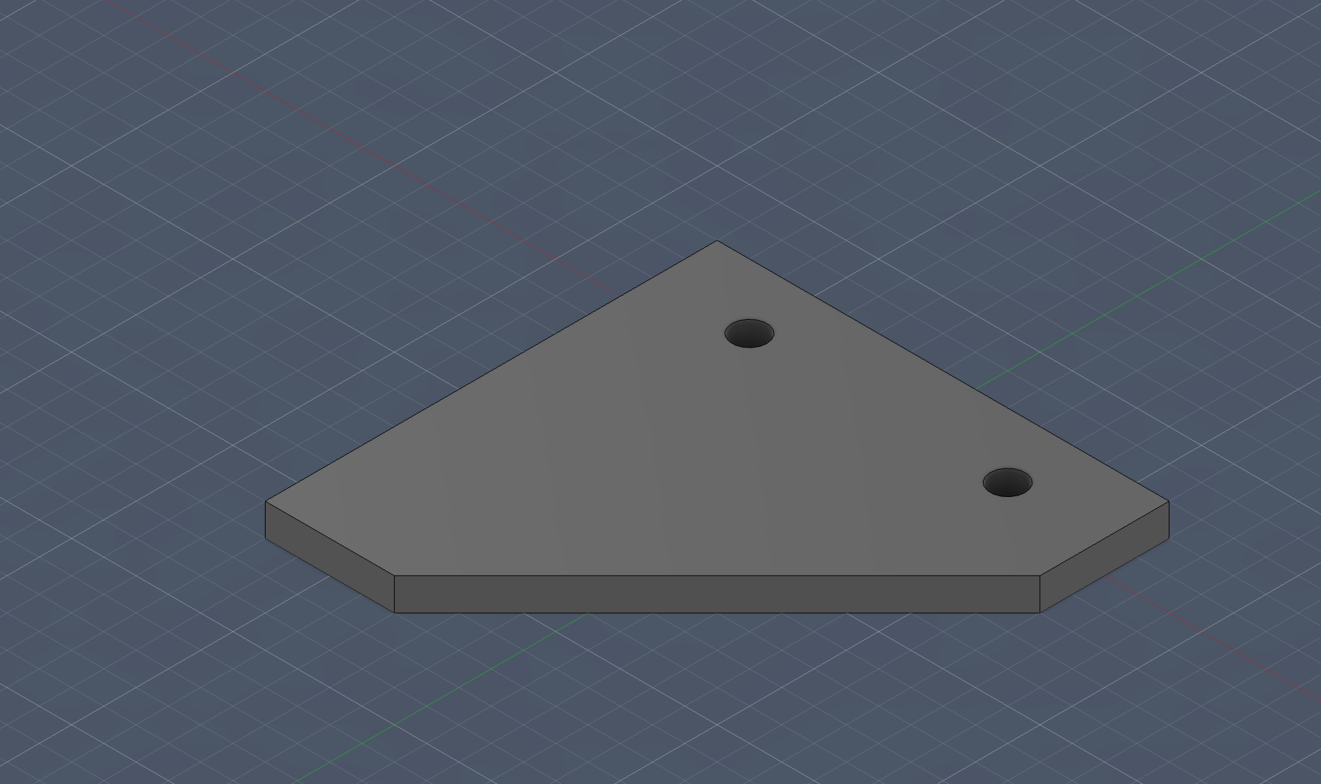
Feet
not much to explain just feet for the rail’s to stand up
I kept this part intentionally simple because I wanted something quick, strong, and easy to reprint if dimensions changed later. For me, this was one of those “small part, big impact” moments because bad feet would make every later alignment step harder.
Motor Mount
Hero Shot
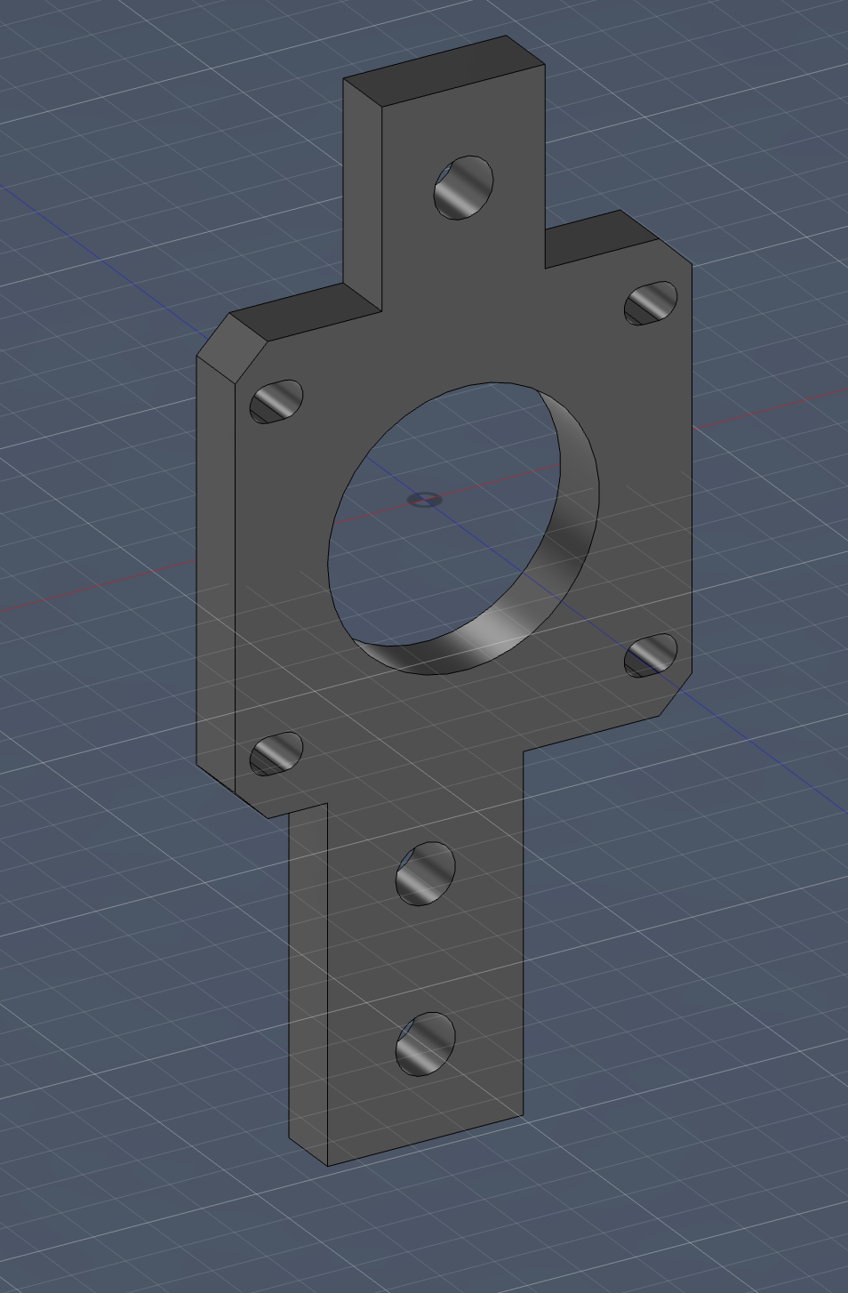
Explanation
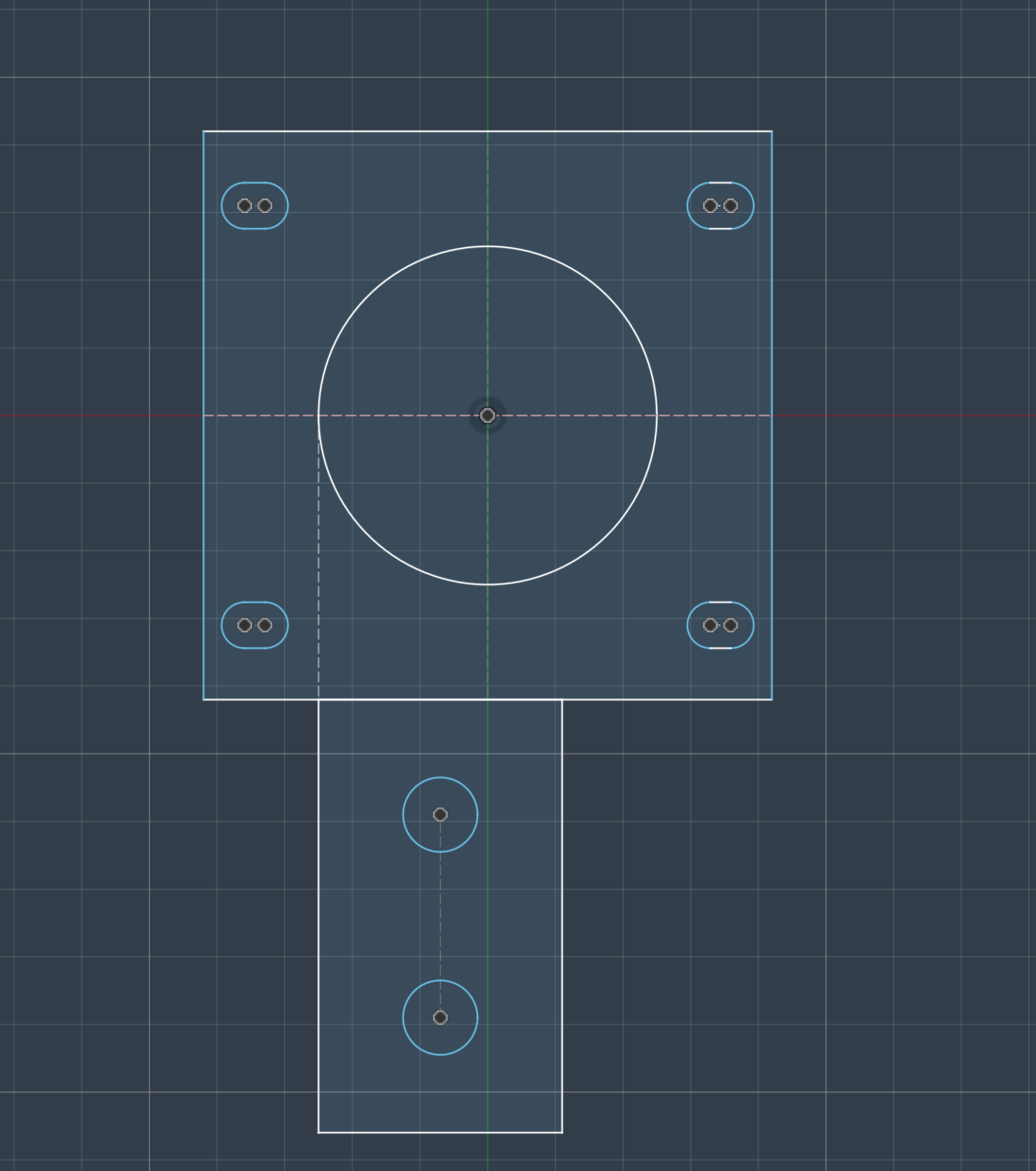
This is the initial sketch, which mostly makes up the base of the motor mount. The mount hole is fitted for a NEMA 17 motor. The slot holes are for M3 screws, while the two large holes are used to stabilize the holder on the profiles.
The downward part of the holder is slightly offset to the right so that the capstan motor and pulleys align with the center of the motor for efficient movement. As you can see, it is directly aligned with the left side of the motor mount as well.
Next, it was extruded and extended onto the other part of the sketch.
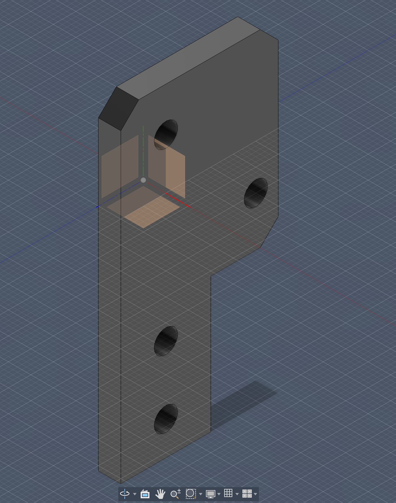
I added this top part: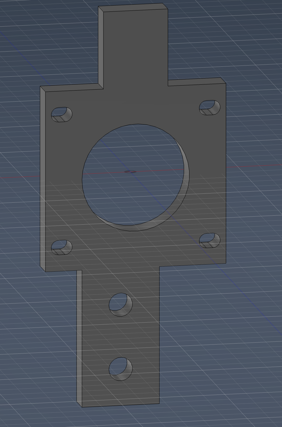
Then I created a precise cutout: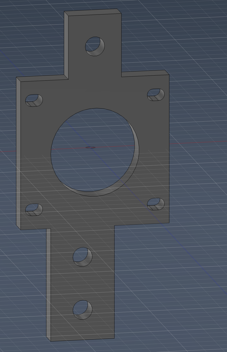
This was done so the pulley could fit behind the motor’s extension on the NEMA shaft.
My main focus here was avoiding future rework. I spent extra time on alignment in CAD because if the motor mount is off even a little, the thread path becomes annoying during assembly and testing.
The motor mount is done.
Pulley Mount
Pulley Mount
Not much to explain - just a simple pulley mount to attach the pulleys on the moving axis.
I still treated this as a precision part, even if it looks simple. My goal was to keep pulley position predictable so tensioning the thread later would feel less like trial-and-error.
Capstan Motor
I first wondered what a capstan once since my mentor always asks the definition of every small thing. LITERALLY EVERYTHING. A capstan is a vertical-axled rotating machine developed for use on sailing ships to multiply the pulling force of sailors when hauling ropes, cables, and hawsers.
How a Capstan Works
A capstan is a vertical-axled rotating machine developed for use on sailing ships to multiply the pulling force of sailors when hauling ropes, cables, and hawsers. At its core, it works on a simple mechanical advantage principle: humans push on horizontal bars (called capstan bars) that extend outward from a central drum. Because these bars act like long levers, even a modest force applied by each sailor becomes a much larger torque around the central axis.
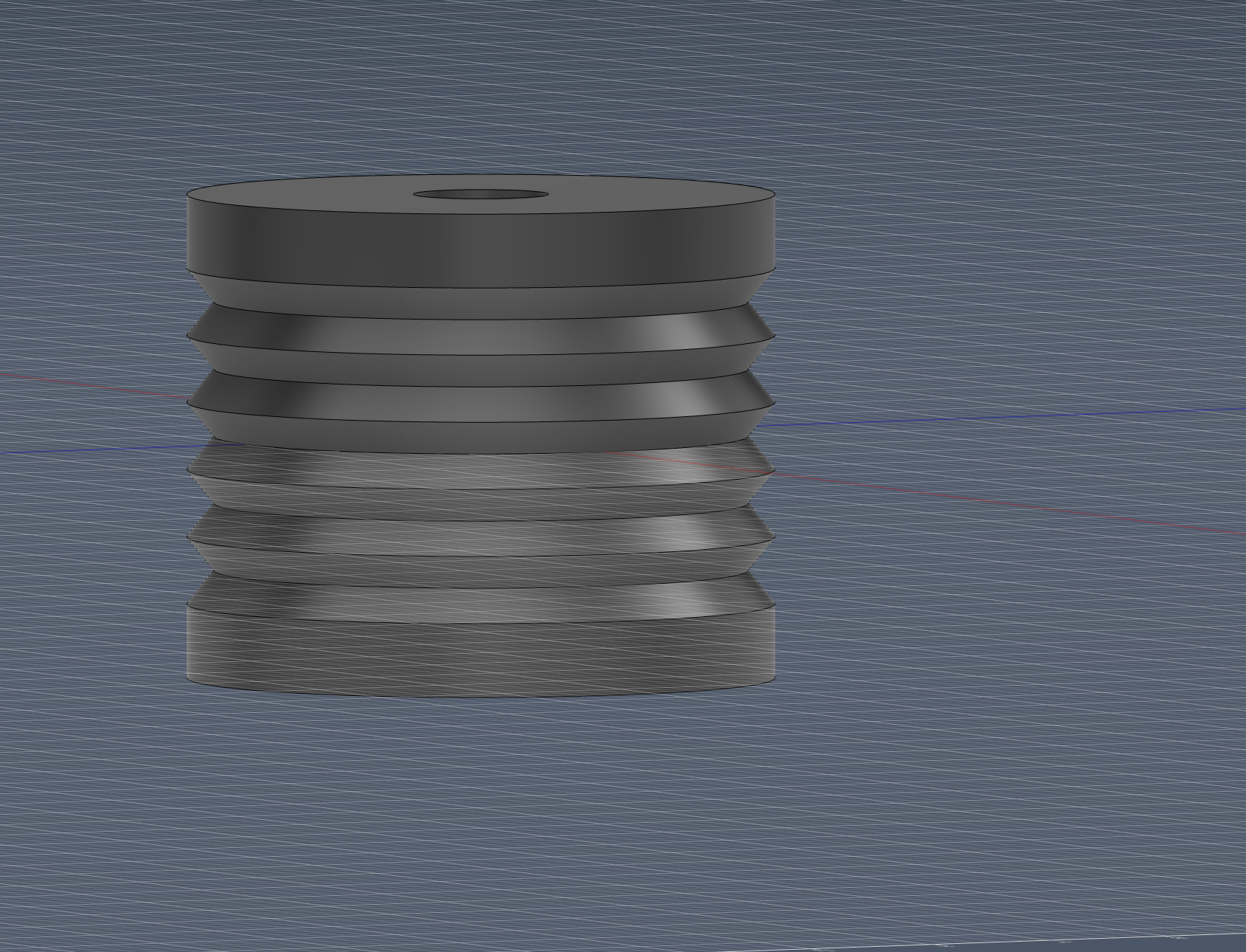
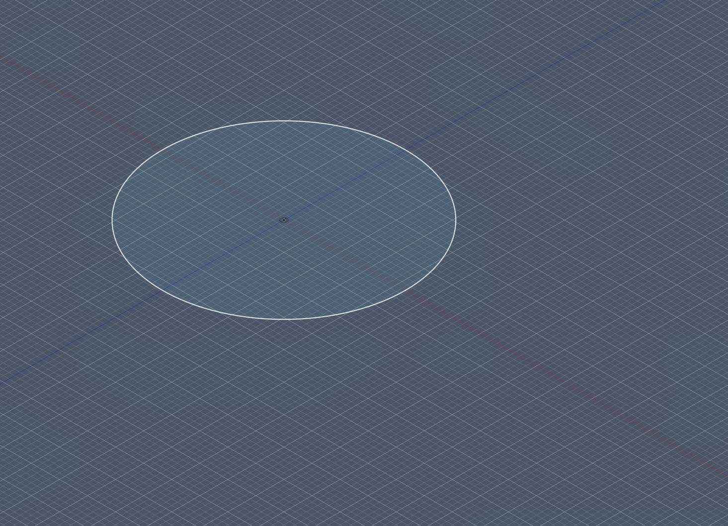
CAD
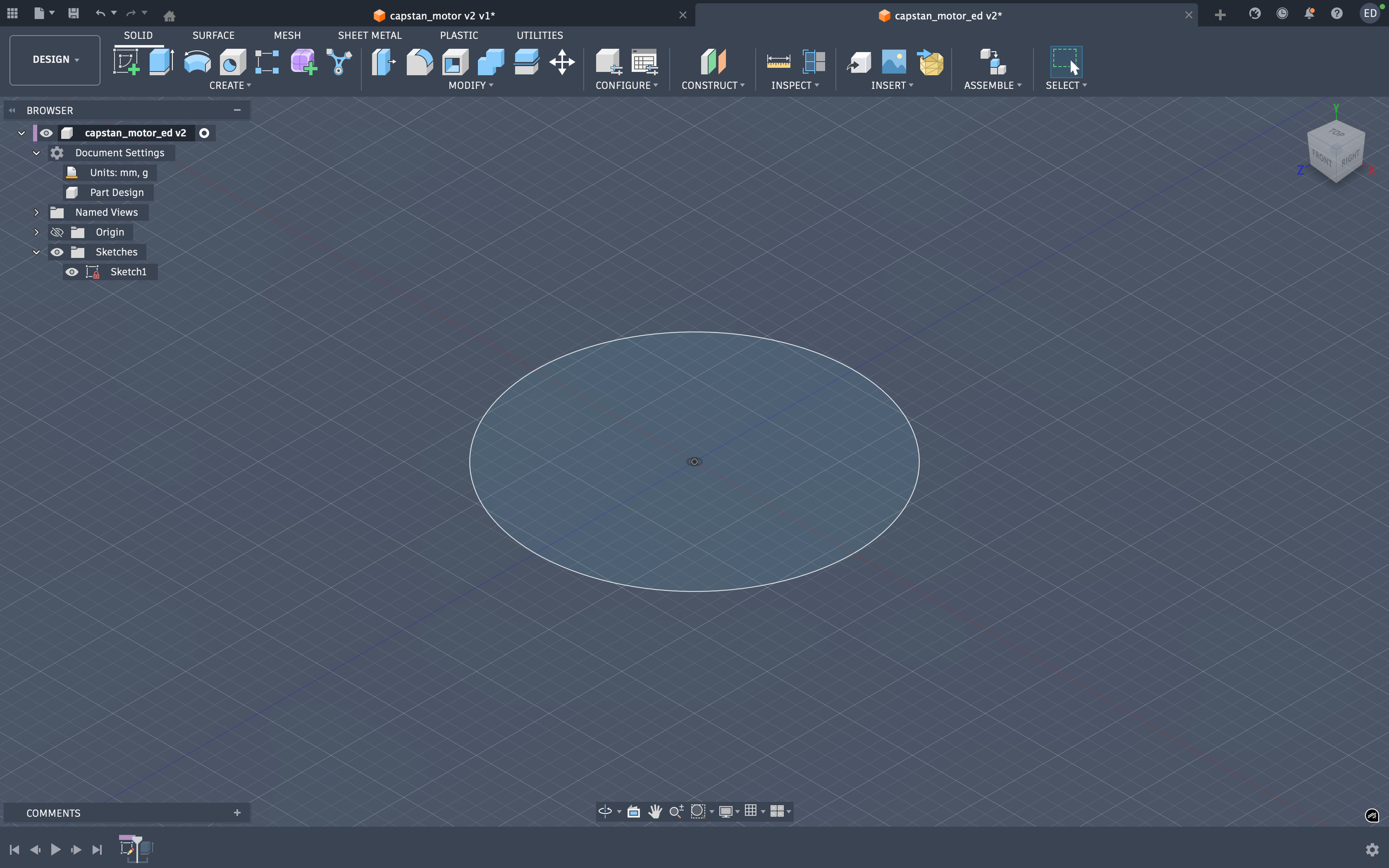
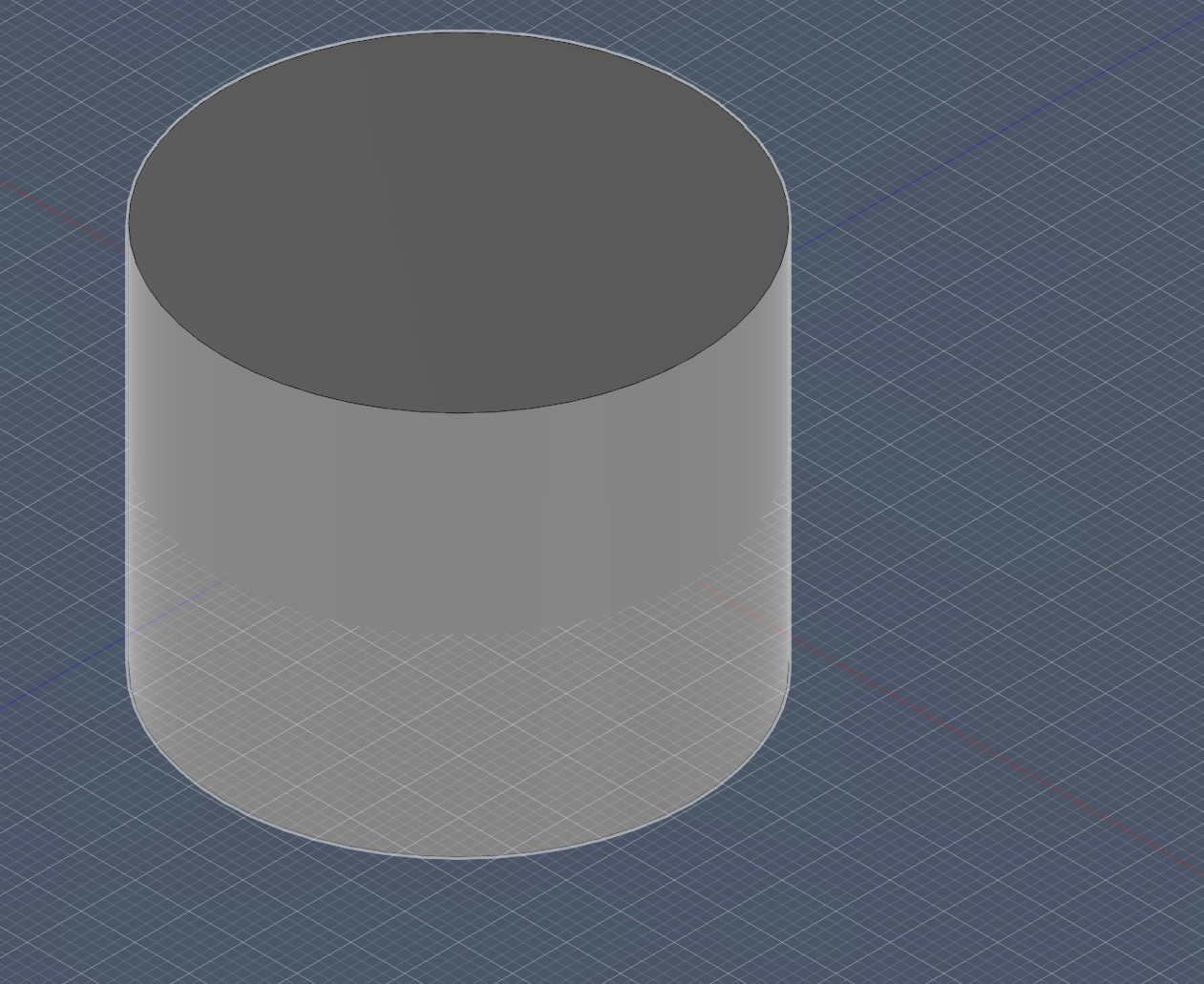
I first created the base of the capstan
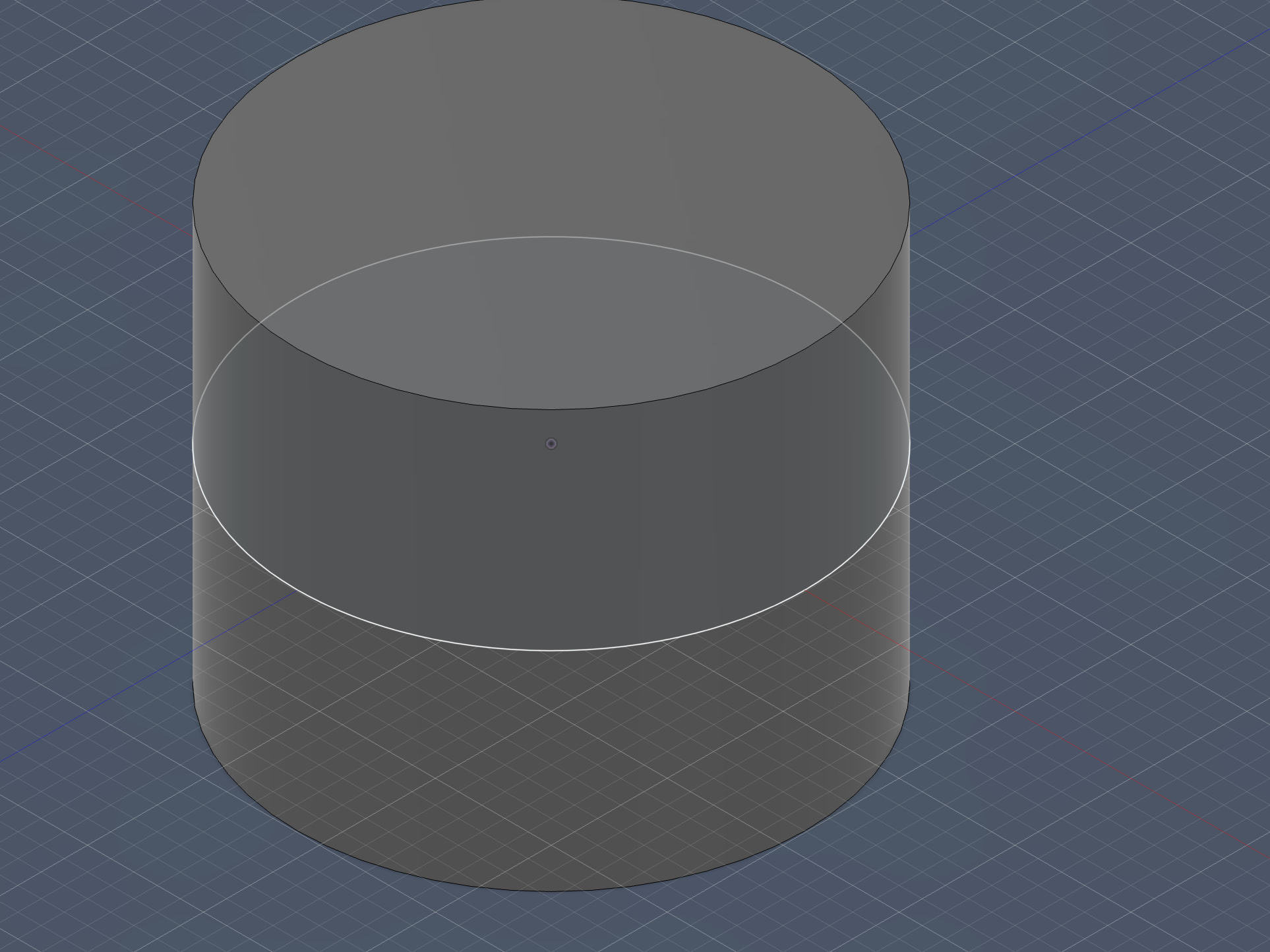
 then I extruded it
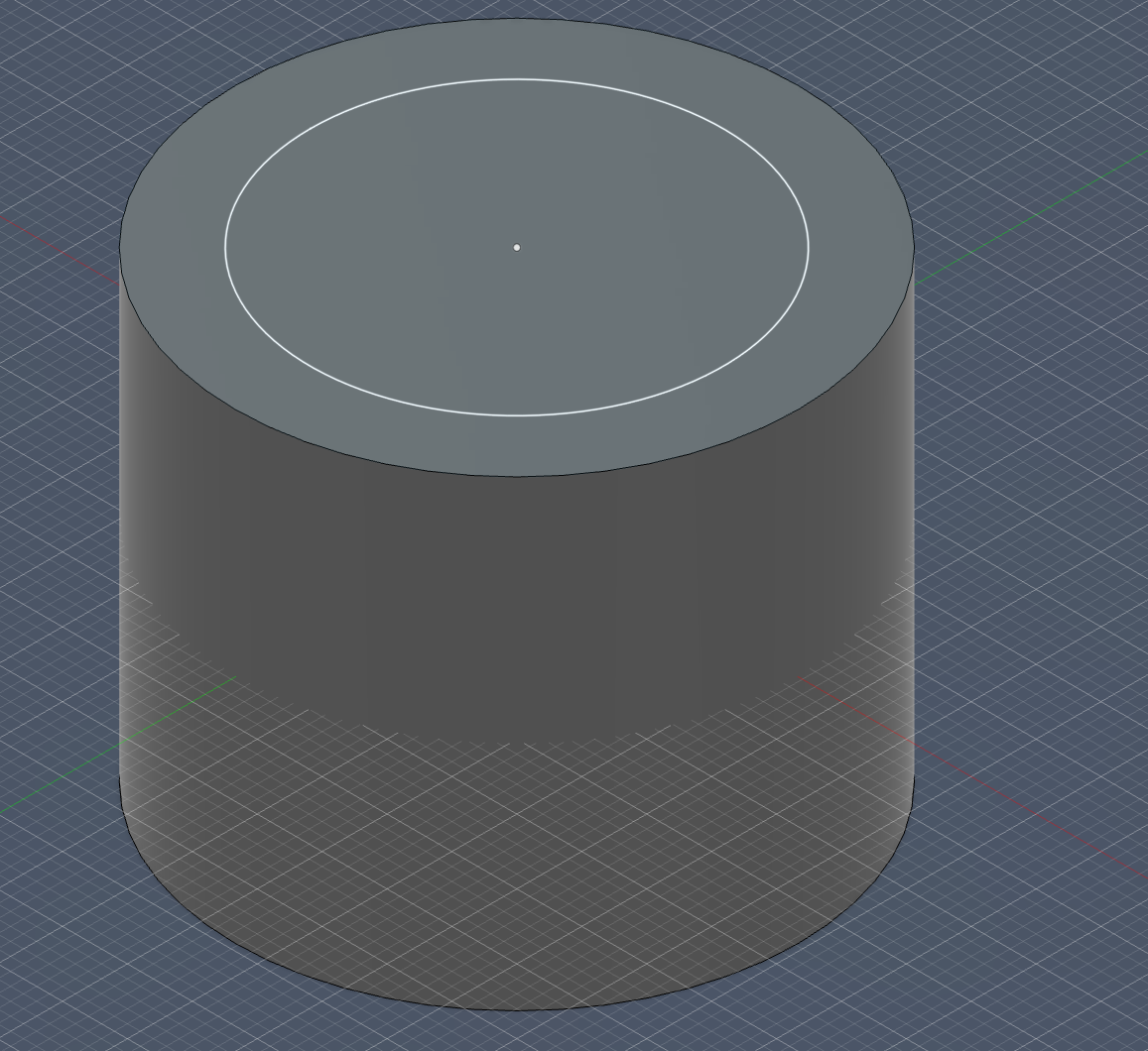
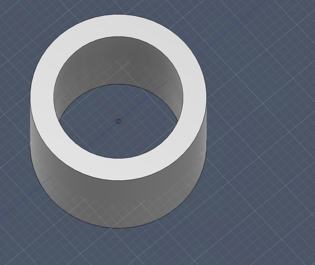
 next I sketched the top hole
and then cut it through the body
next I sketched the top hole
and then cut it through the body
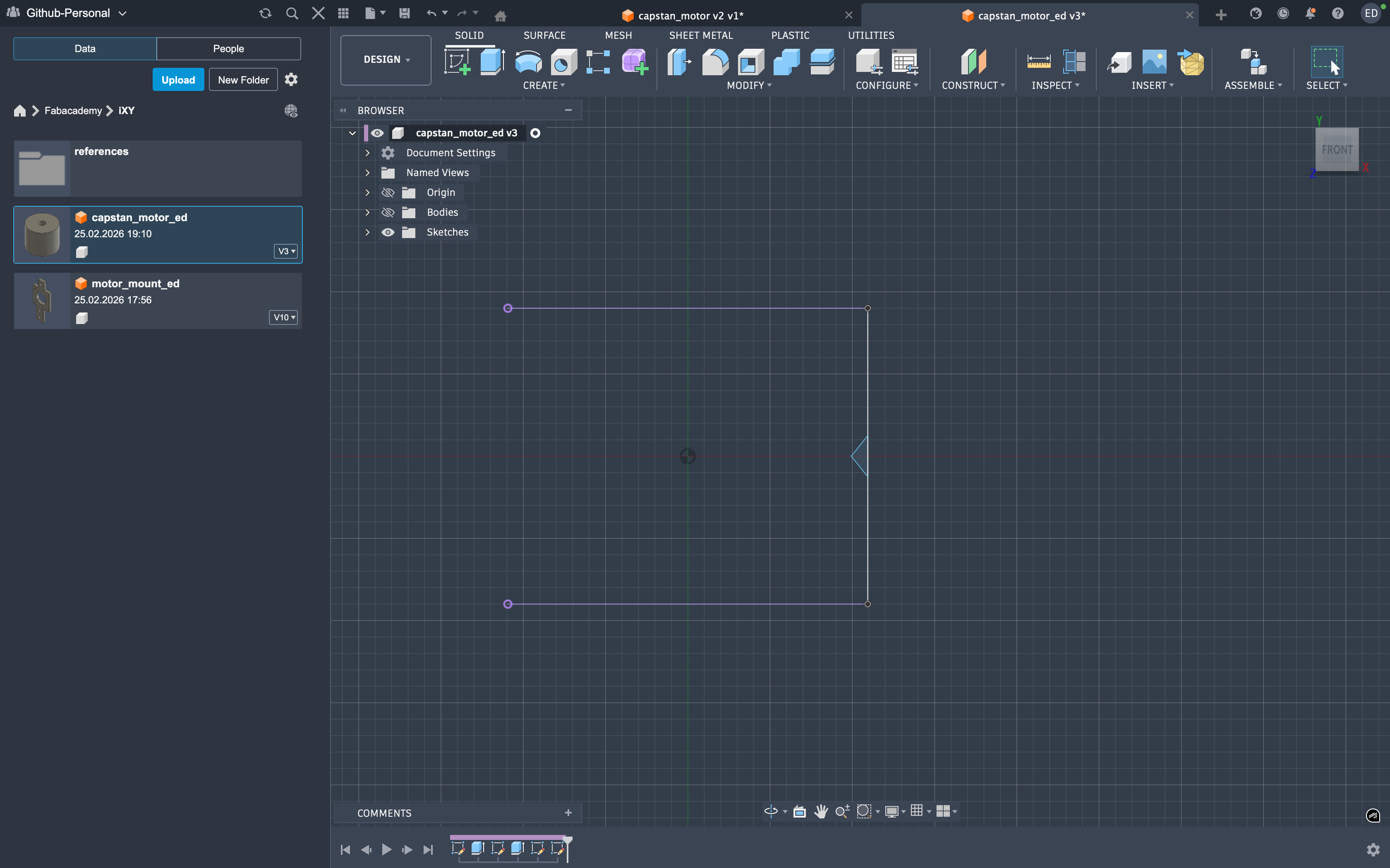
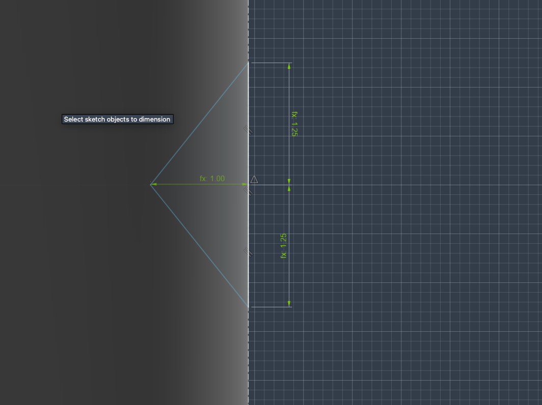
 Then it was time for the revolute but before that I projected the two circular faces on the xy to properly setup the revoluting body
then setup the tri to be revoluated so the string could wrap around
Then it was time for the revolute but before that I projected the two circular faces on the xy to properly setup the revoluting body
then setup the tri to be revoluated so the string could wrap around
 post rev
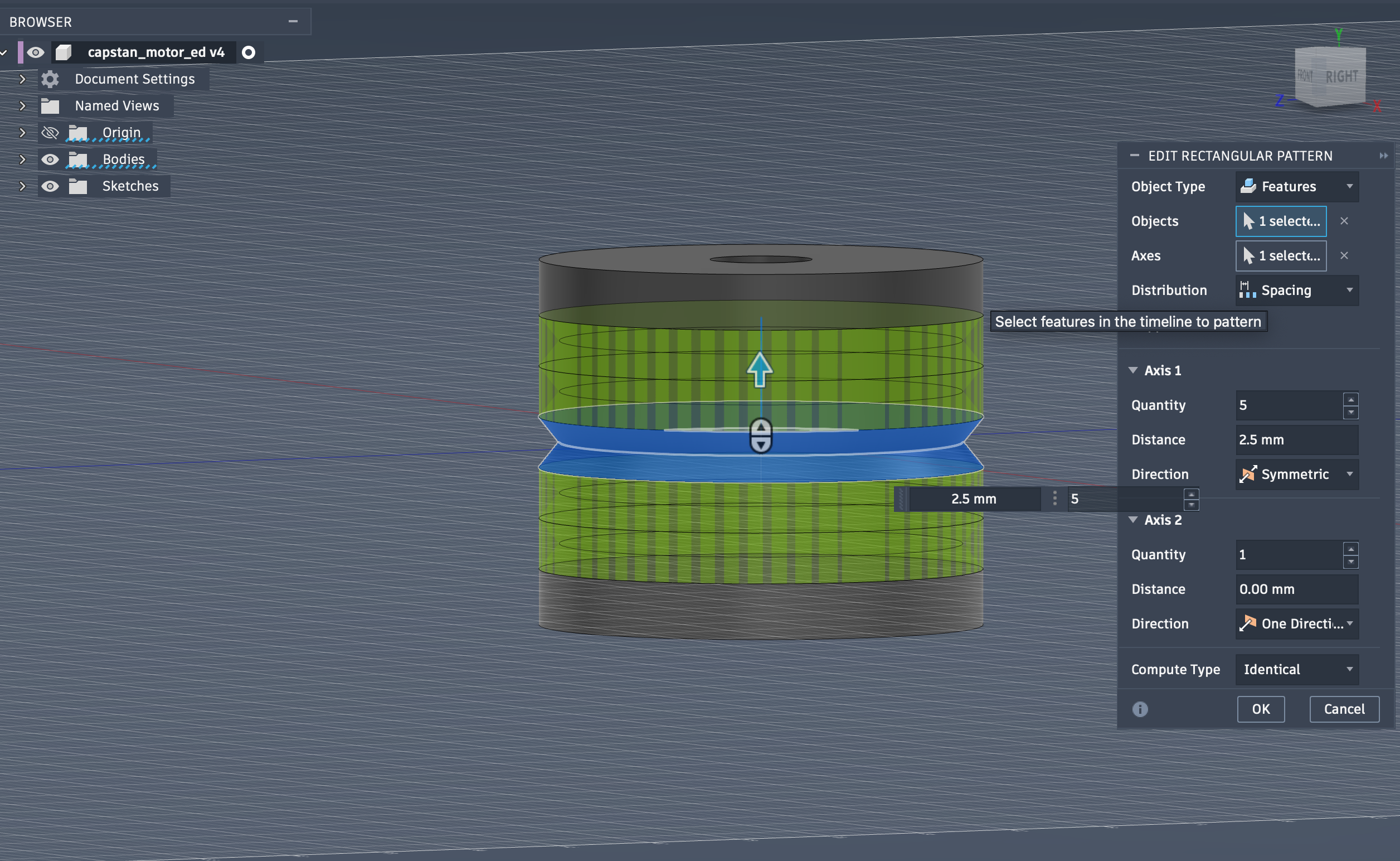
 next I repeated the revolute using the R-pattern for the thread to easily go around the whole body
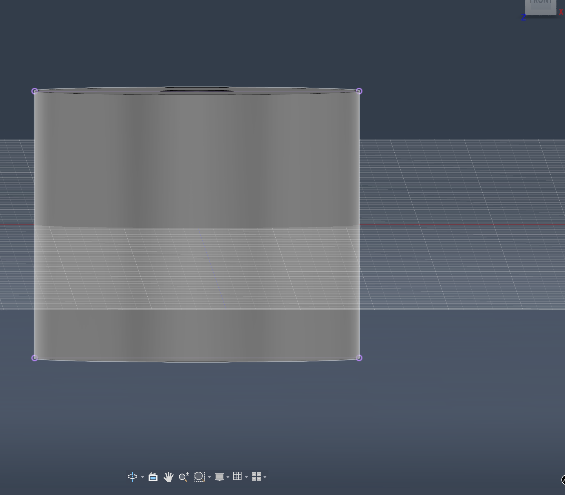
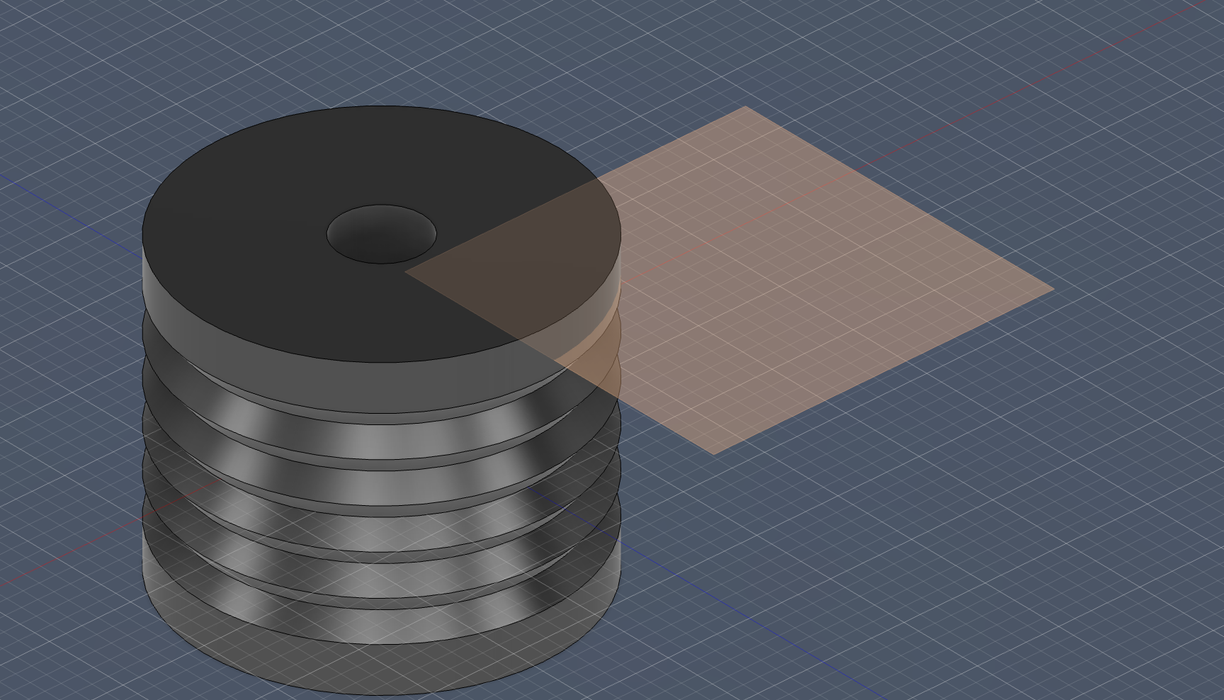
 finally I closed off the top since we don’t need a hole there and it was only temporary! I closed it using the added construction plane by doing a to object extursion of the hole from the top to the plane creating a snug fit for the motor shaft
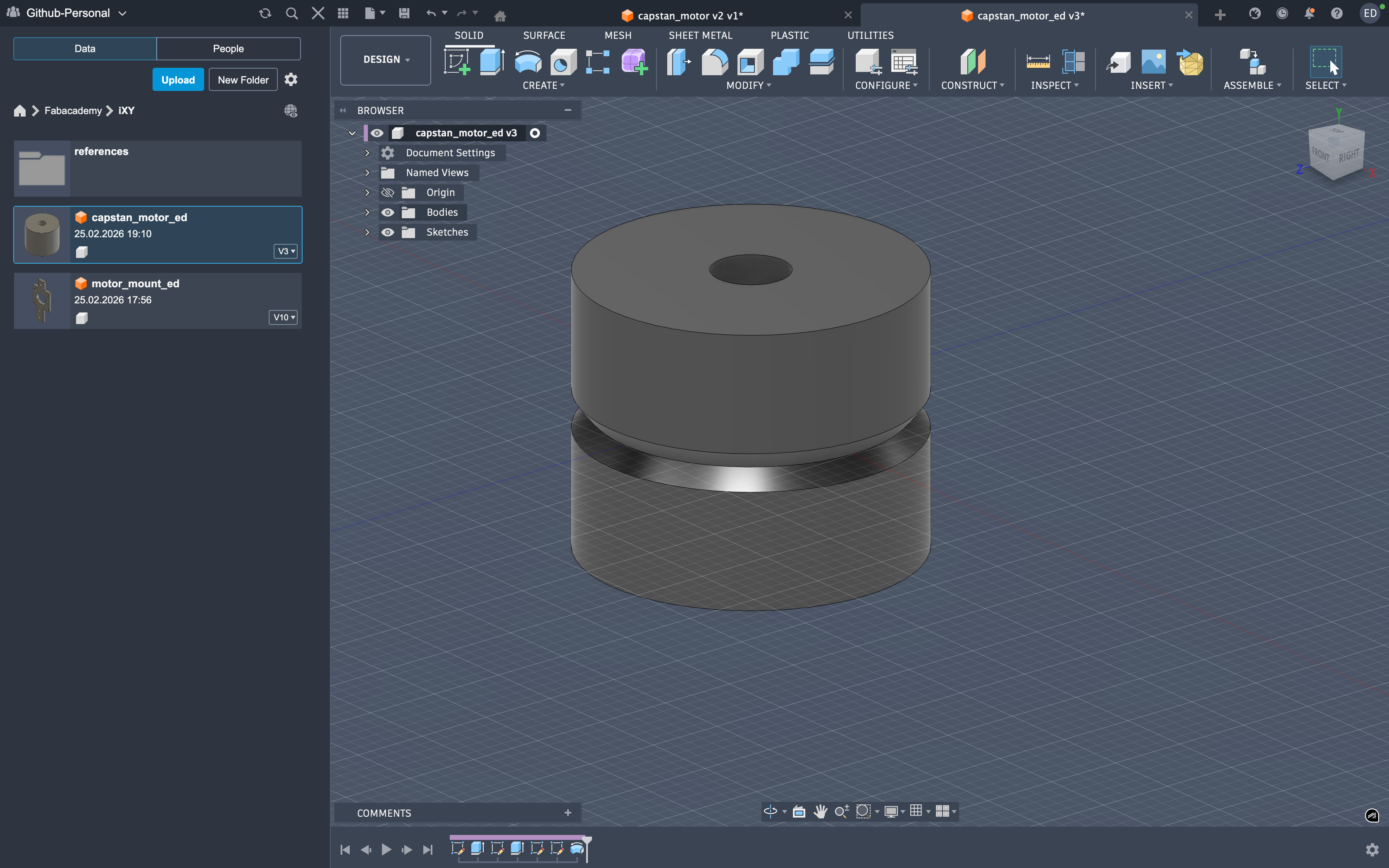
 final shot
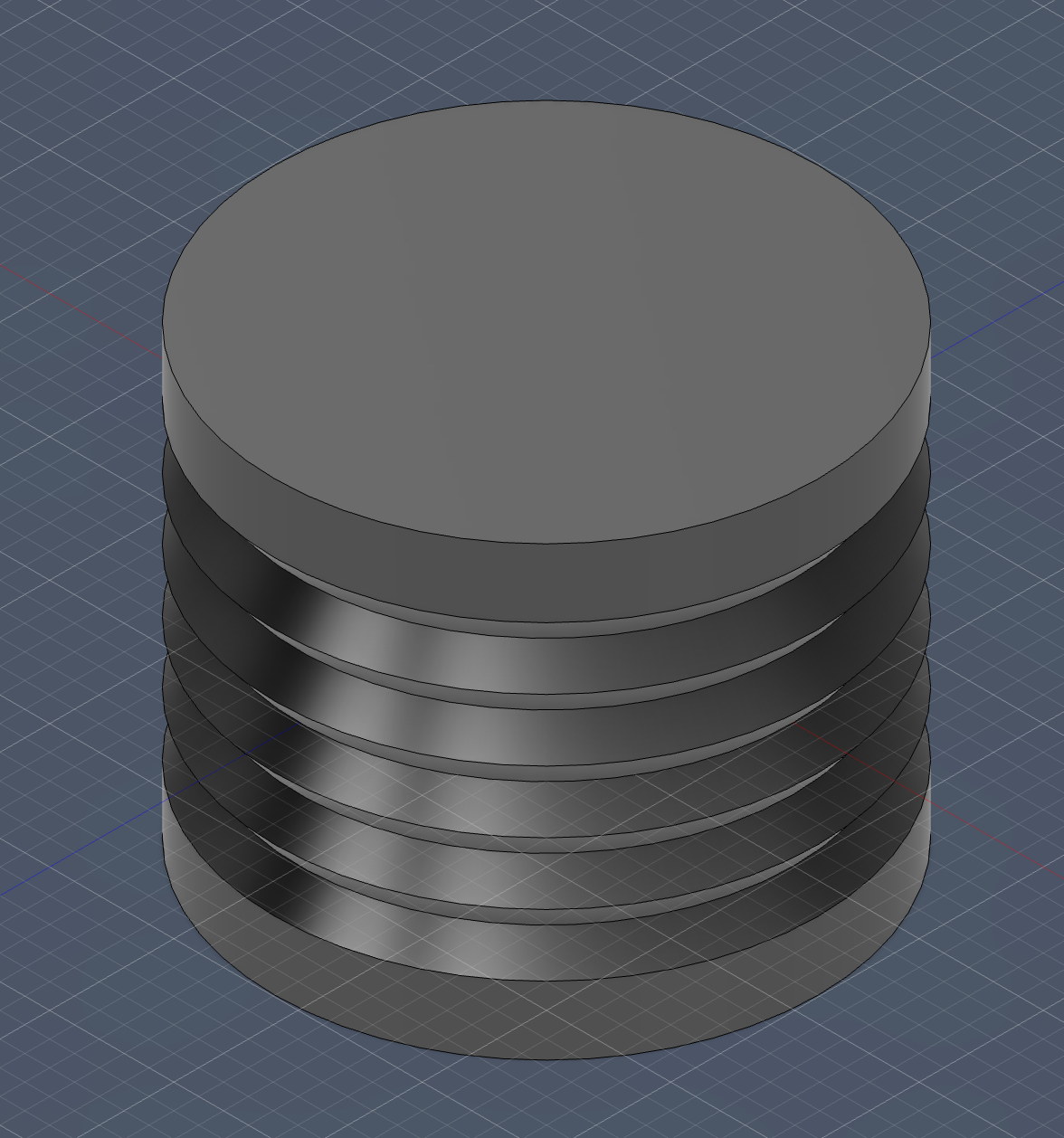 This part took the most patience for me. I iterated the revolved profile until the thread contact felt “right” in my head, because I wanted smooth wrapping without sharp geometry that could wear the line.
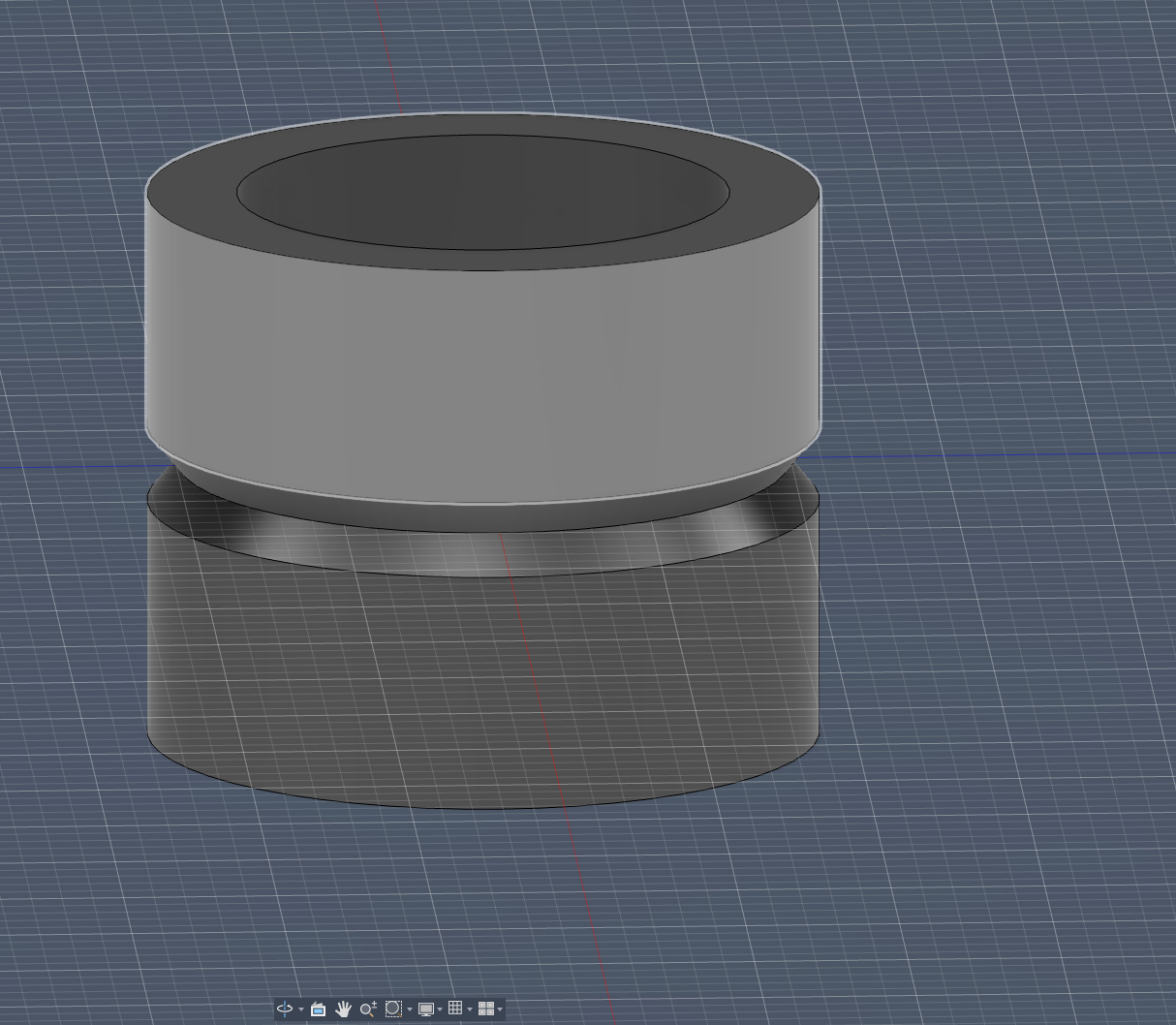
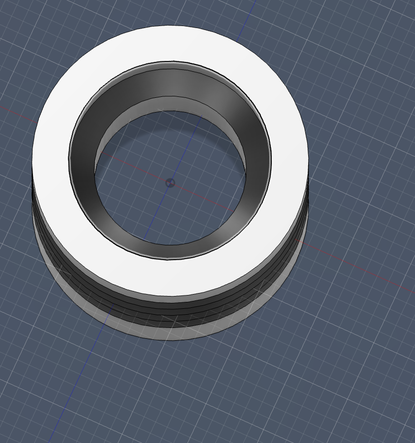
Capstan Pulley
Again, I did the base circle with the said dimensions:
Then, using symmetric extrusion, I extruded it to 18 mm:
Next, I sketched and performed a through-hole cut for the top hole:
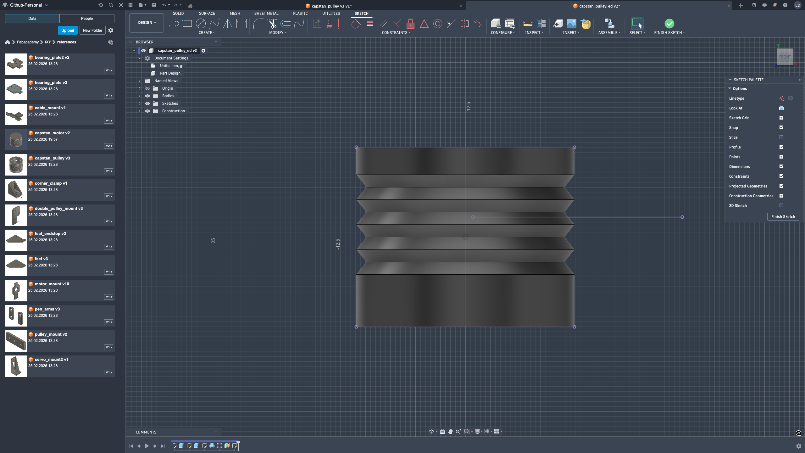
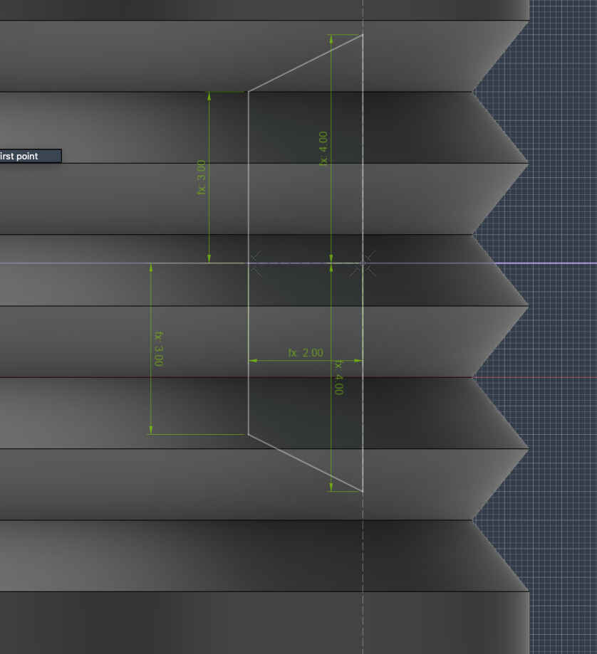
After that, I created the revolution triangle sketch:
And revolved it:
Then I created a construction plane to draw the bearing holder:
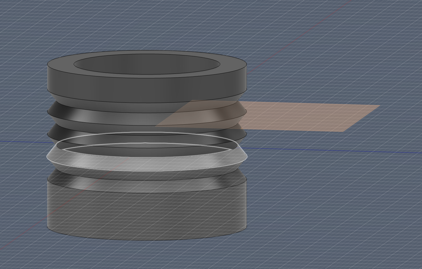
I projected that side of the construction plane onto the ZY plane to make another revolve template:
Next, I added the revolution sketch:
Final result:
 I liked this step because it felt like pure geometry problem-solving. I moved between sections, revolves, and construction references until the part looked mechanically clean and printable.
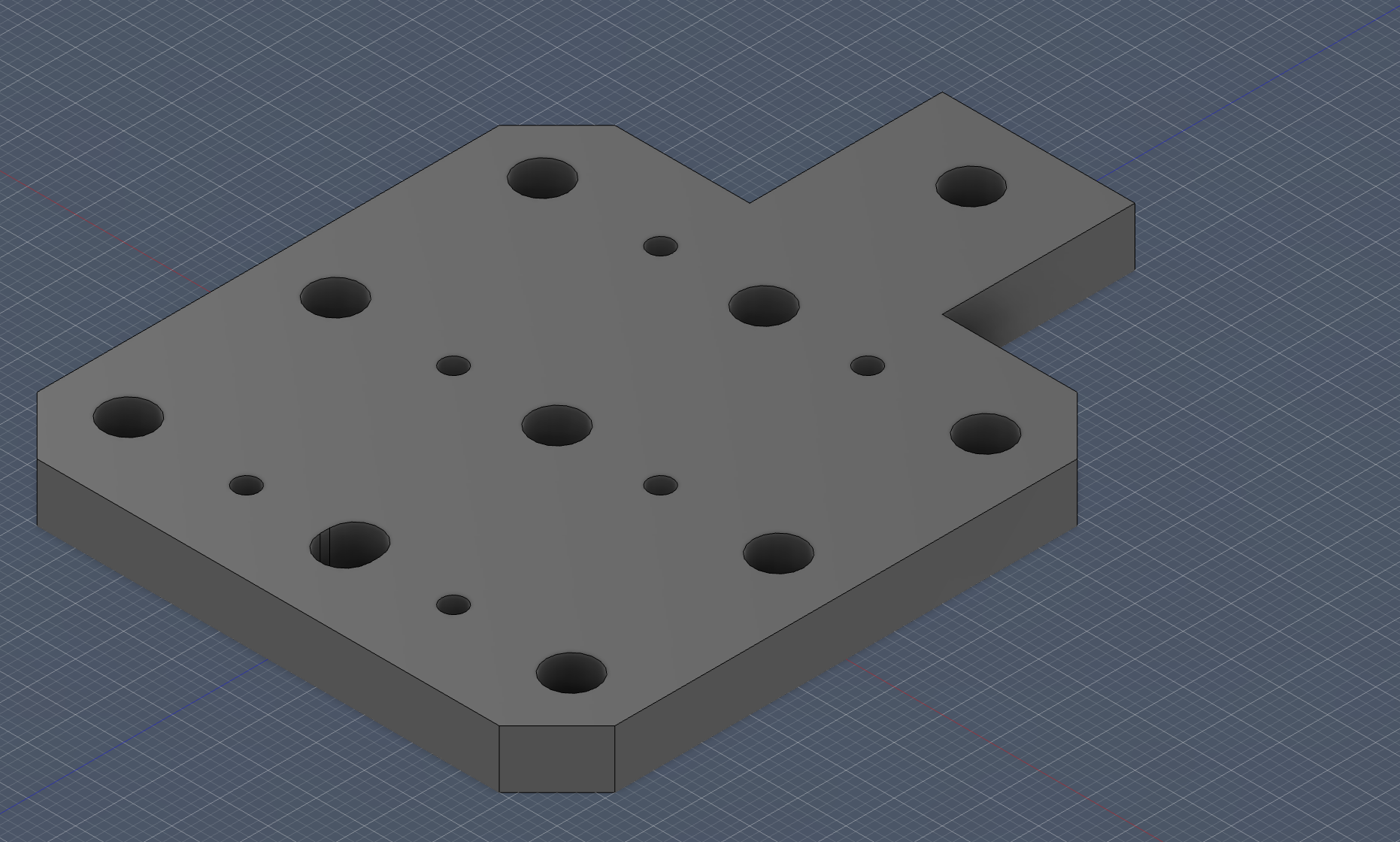
Bearing Plate (Version 1)
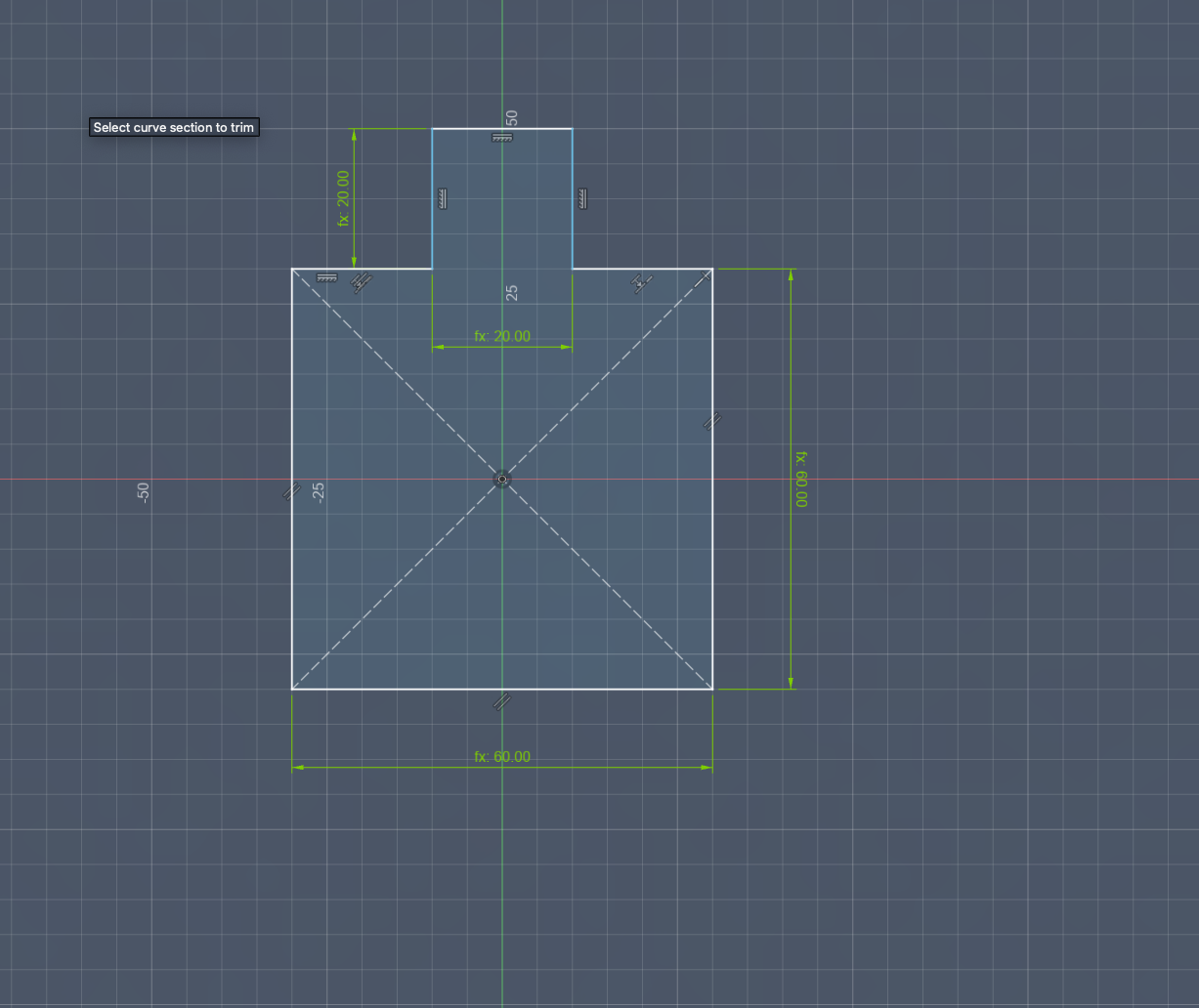
Bearing Plate Design Process
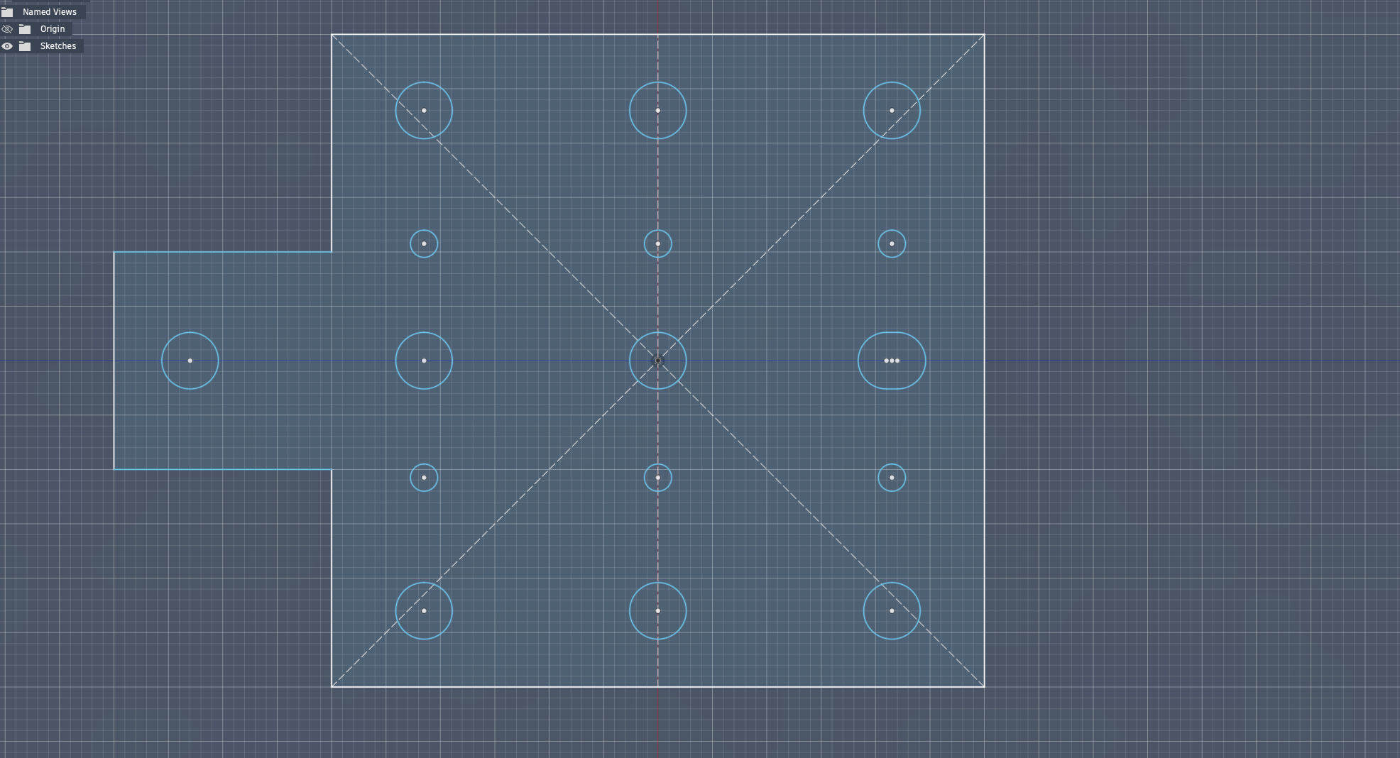
First, I created the base sketch.
 Then, I added the screw holes.
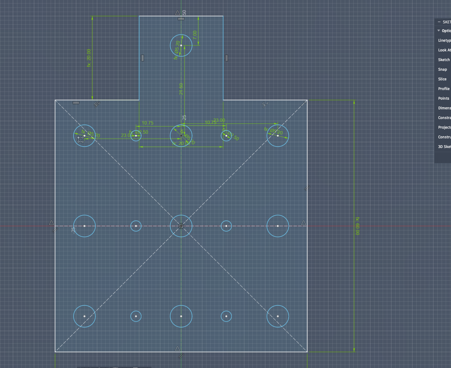 Next, I modified the back hole into a slot with slightly more clearance.
 After that, I extruded the sketch.
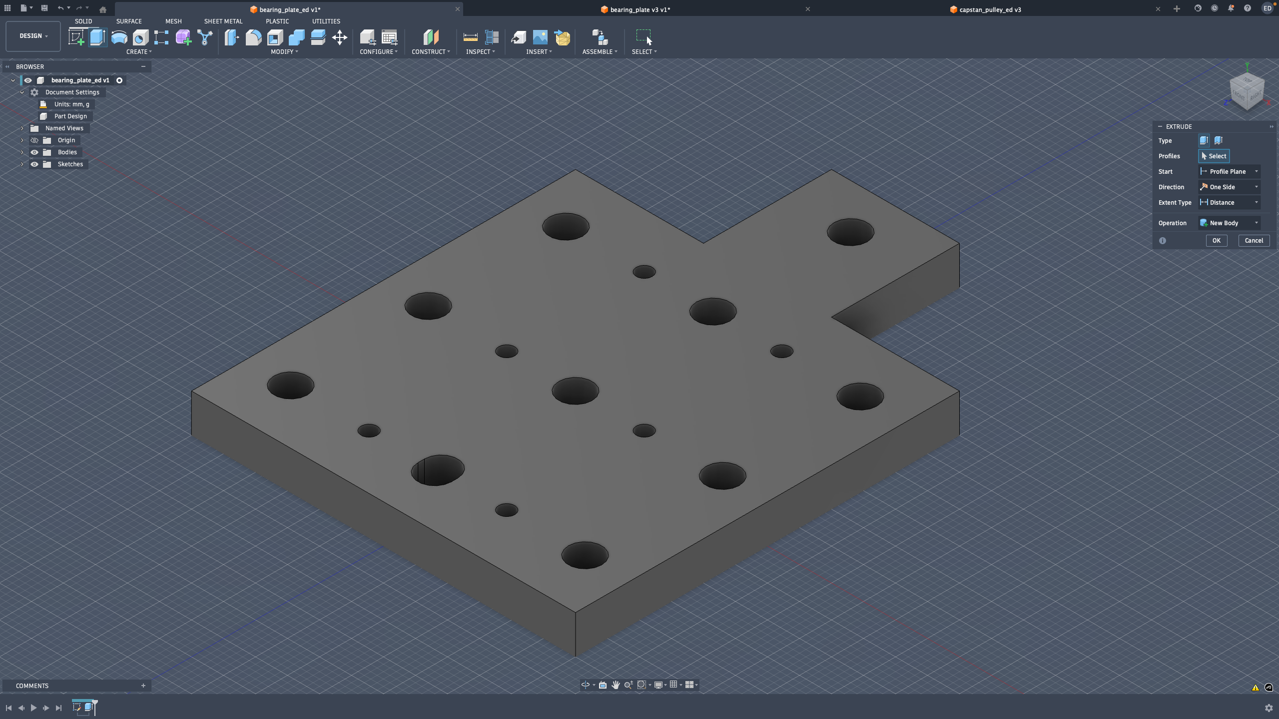 Then, I chamfered the outer edges.
 Finally, I added chamfers to the bottom square edges and fillets to the top square edges. The design was complete.
 For this plate, my priority was practical fit over visual perfection. I gave small clearances where needed so assembly in real life would be forgiving.
Bearing Plate (Version 2 - Base Part Design)
Base Part Design
First, I created the base sketch:

Then, I added the screw holes:

Lastly, I modified the back hole into a slot with slightly more space:
Next, I extruded the part:

Then, I chamfered the outer edges:

Finally, I added chamfers to the sides of the bottom squares and fillets to the sides of the top squares. The design was then completed:
 This second version came from me learning by doing. After testing the first approach, I understood where I needed less material and where I needed more mounting flexibility.
Bearing Plate (Version 2 - Iteration Notes)
first I created the base sketch Then I added the screw holeslastly I modified the back hole to be a slot with slightly more space
 then I extruded
 then I chamfered the outer edges
 finally I added chamfers to the bottom squares sides and fillets to the top squares sides and the design was done
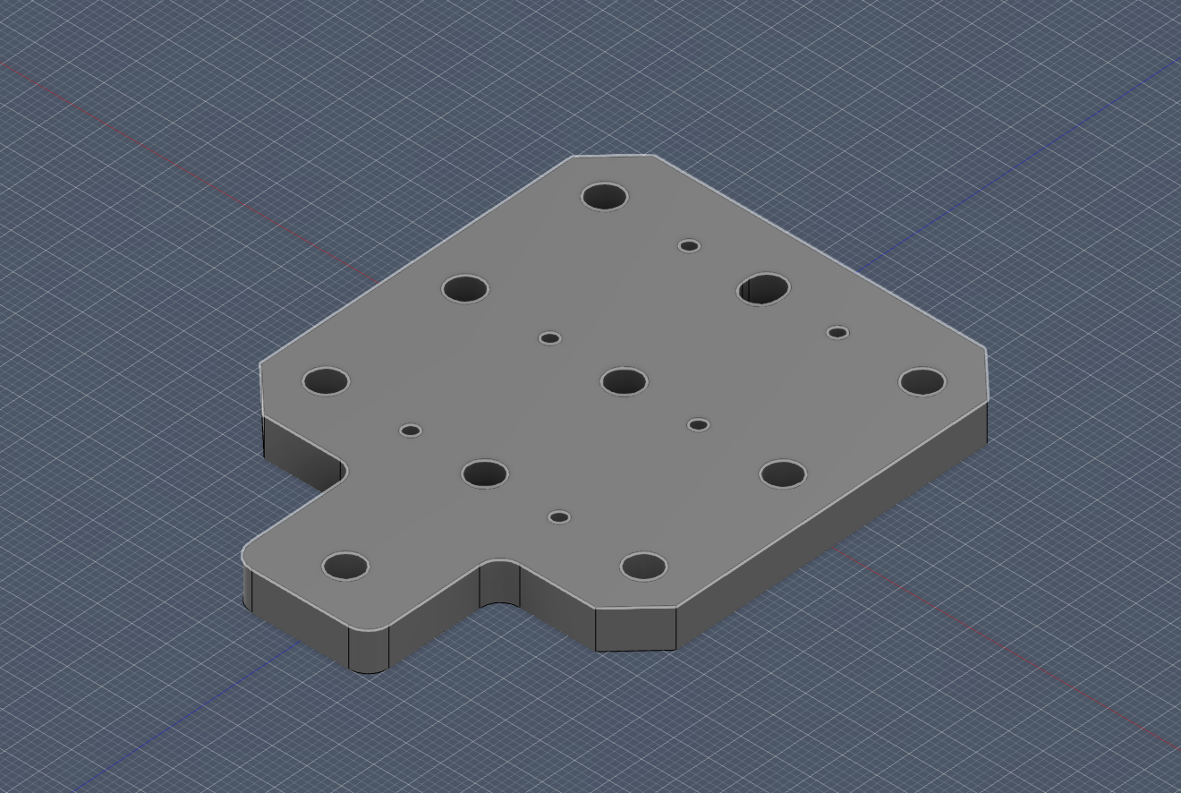 now it was onto making the further modifications as for a version of the plate with less holes for parts a smaller plate for purposes needing one as such. First added the bottom slot cutout.
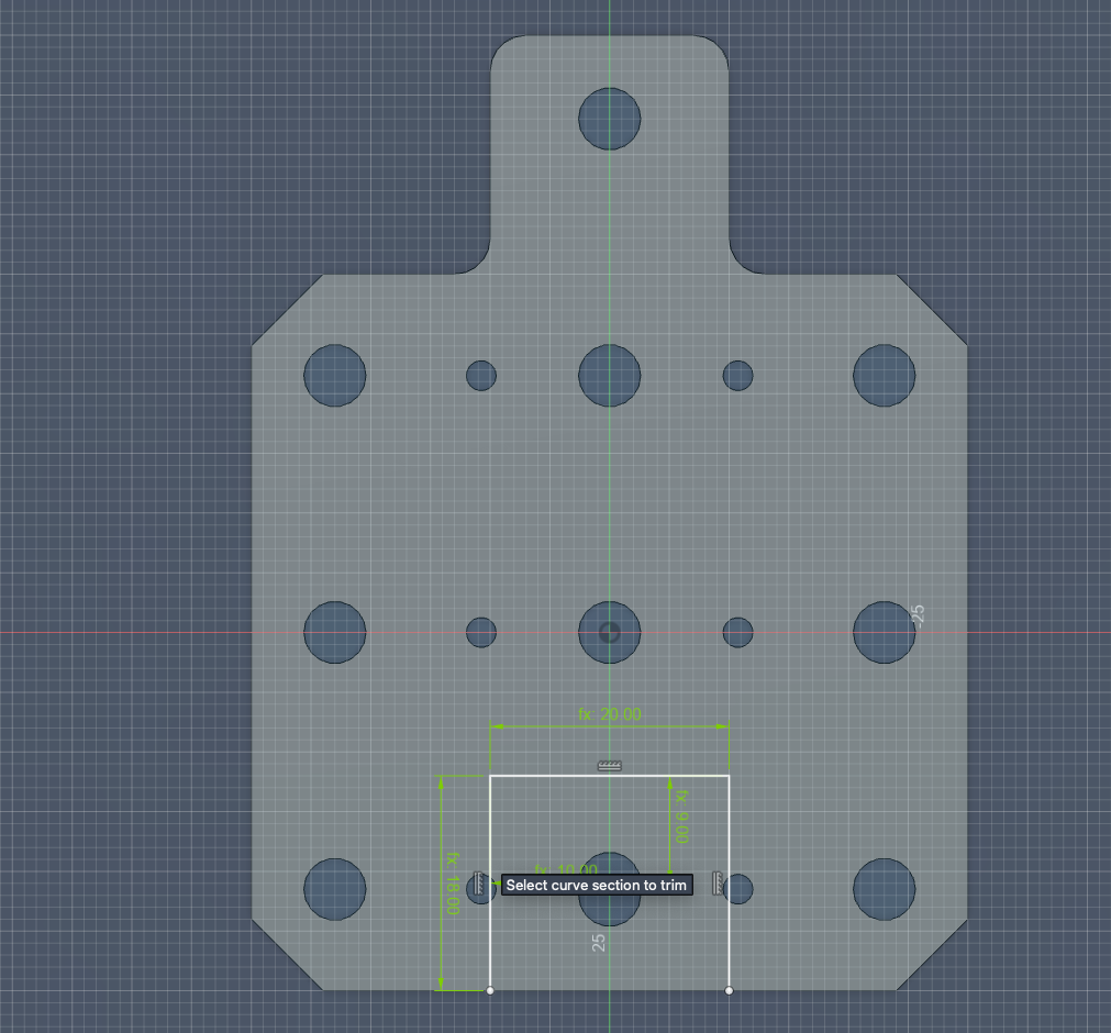 Then the top cut out
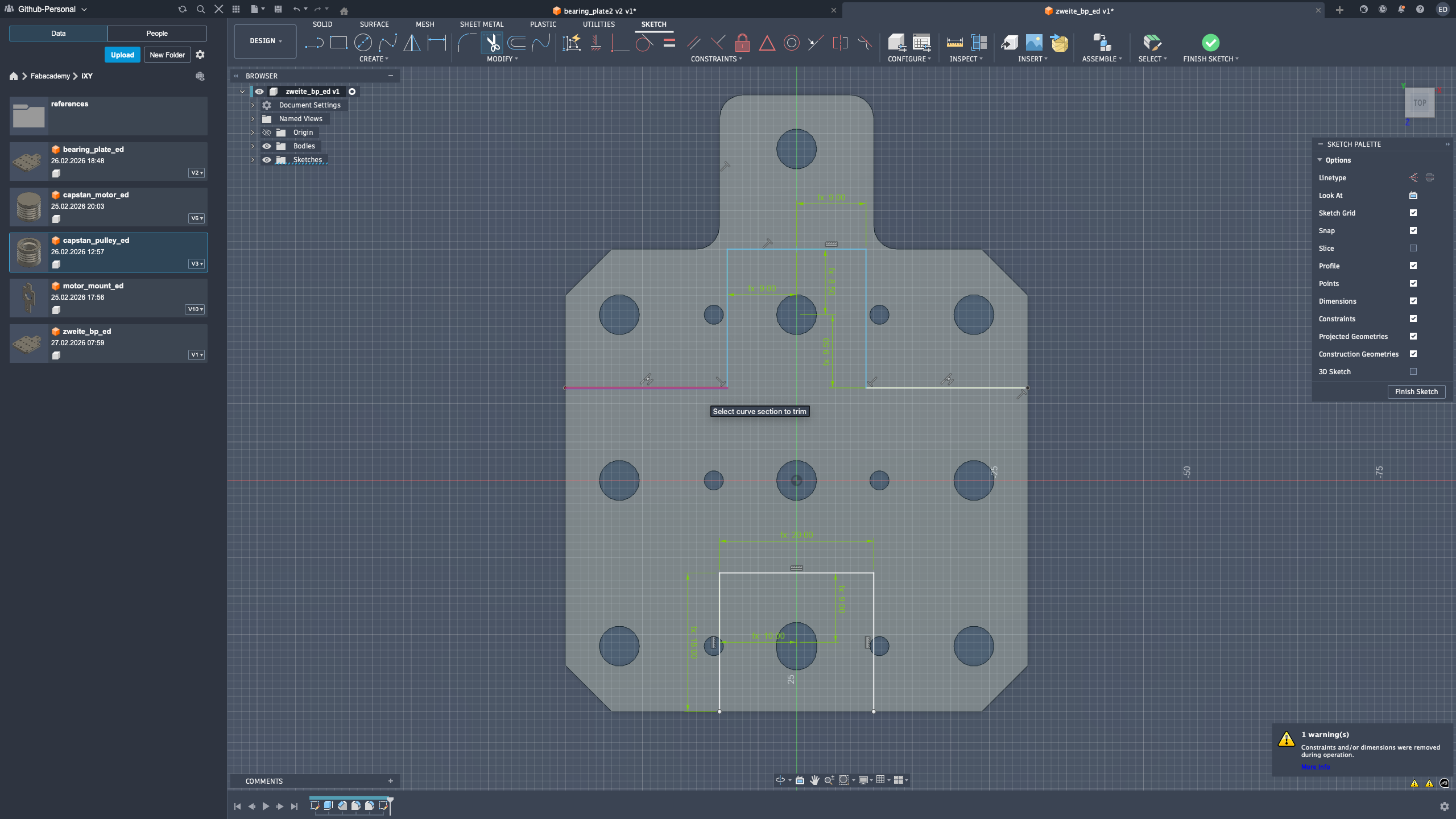 finally I did the extrusions and got this
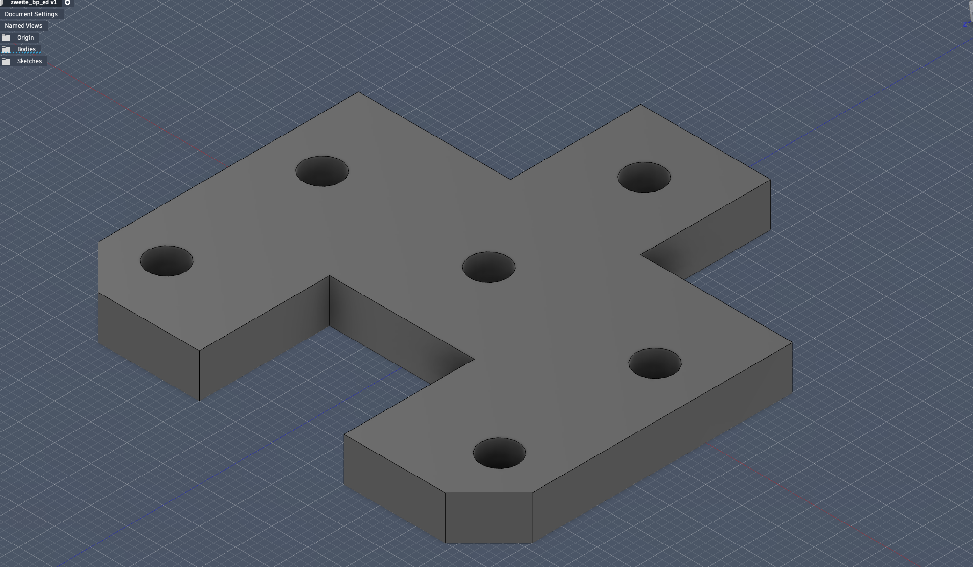 fail time.) I later realized that I didn’t need the smaller screw holes in the repeated formation that was given in the bp1 thus I went back in the sketch and got rid of them in the intial sketch and now will re-add them in appropriate locations that work for the piece
I sketched and constrained them, and then cut em out to have the final zweite bp!
This iteration was honestly the most “real engineering” part for me: make a choice, test it, notice what is unnecessary, and go back to simplify. That loop gave me much more confidence in my CAD decisions.
Assembly Documentation (Last)
Core-XY Assembly Documentation
Assignment context
For the pen plotter development, I took the main responsibility for assembling the Core-XY mockup and validating that the mechanical motion system was ready for integration.
My goal in this stage was:
- build a stable frame,
- install and align motor and middle-axis components,
- route the thread/belt correctly,
- verify smooth movement before final machine integration.
Process overview
Full assembly timelapses
Day 1
Day 2
These timelapses document the teams building process
Step-by-step build log
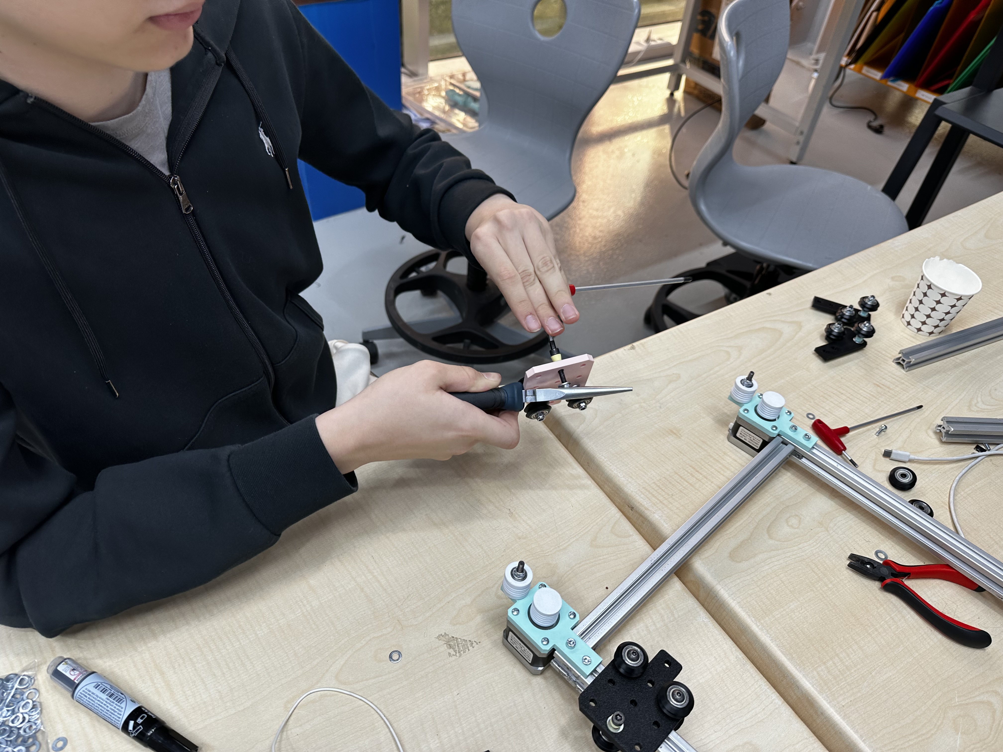
1) Motor mount assembly
I assembled and fixed the motor mounts to the frame. At this stage, I focused on keeping mount positions square and consistent so the later thread path would not drift. I took my time here and double-checked orientation before tightening everything. I know from experience that rushing this step creates invisible errors that show up later as friction or mis-tracking.
2) Thread-to-groove fit check
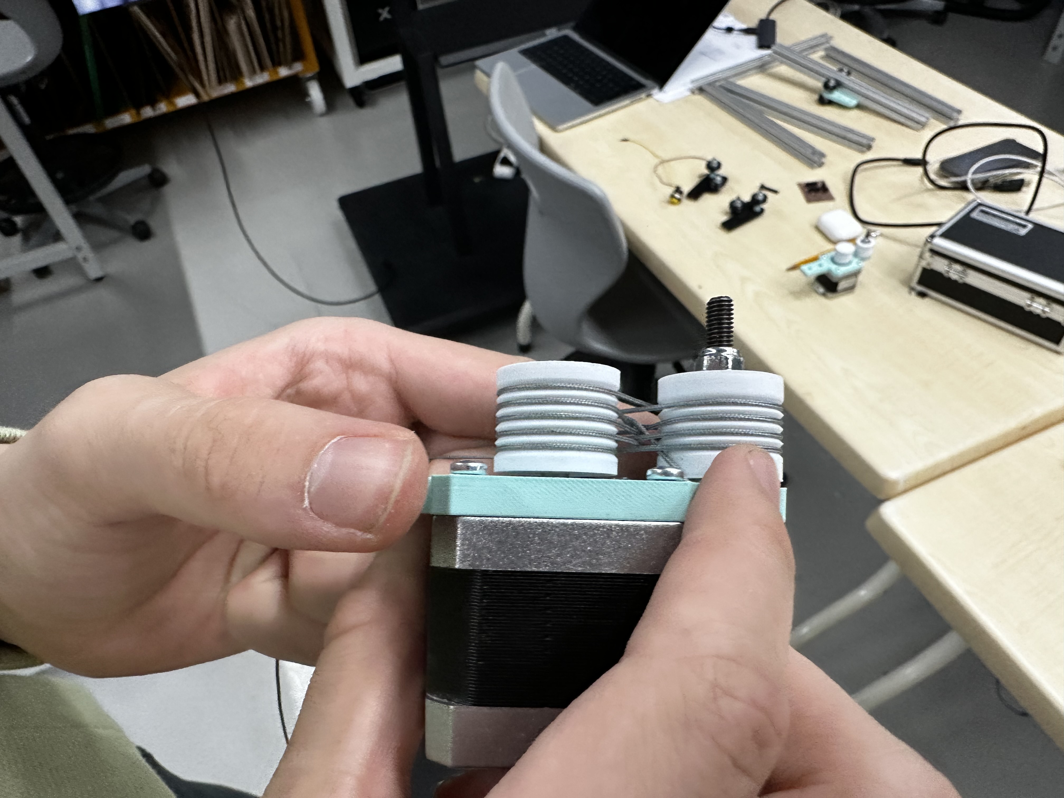
Before full routing, I tested the thread contact in the grooves to confirm fit and seating. This reduced the risk of slip during dynamic tests. This quick check saved me a lot of stress. I prefer catching contact issues early instead of debugging them when the full system is already loaded.
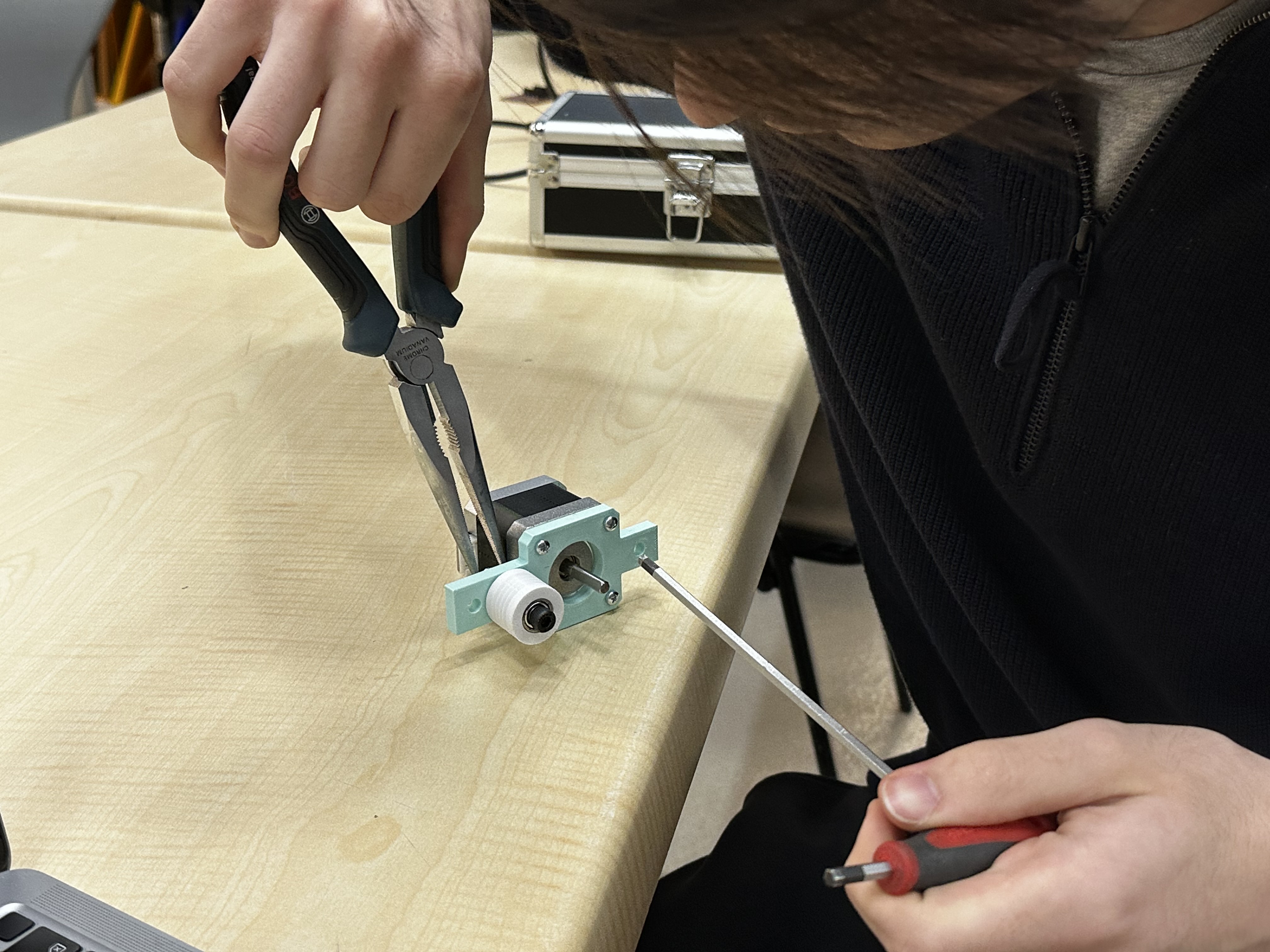
3) Local rope/thread test on motor mount
In this close-up test, I checked local wrapping behavior around the pulley/mount region. This video confirms routing action, but it is a local check rather than full-system validation. For me, this was like a “unit test” for the mechanism. If the local behavior is not clean, I don’t trust full-axis testing yet.
4) Chassis and feet fit test
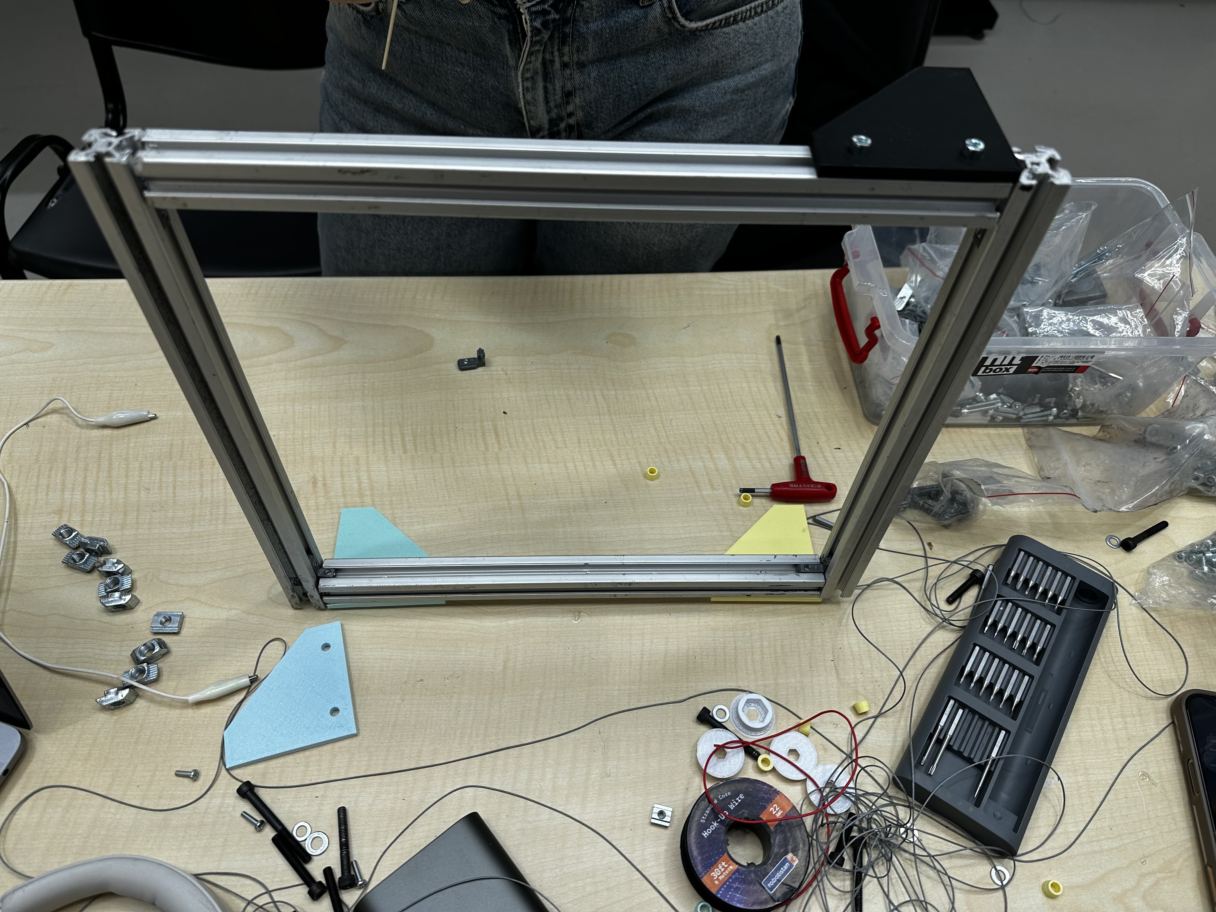
I assembled the chassis and tested the feet fit to ensure the structure sat stable on the table. Stable support was important before installing middle plates. I was happy with this step because the machine finally started to feel physically solid. Once the base stopped wobbling, the rest of the build felt much more controlled.
5) Middle plate assembly
I installed the middle plates and checked the fastening points. This step increased frame rigidity and prepared the mechanism for axis tests. I paid attention to parallelism here, not just “does it fit.” I wanted motion quality later, so I treated structural alignment as part of motion design.
6) Full assembly state before final thread insertion
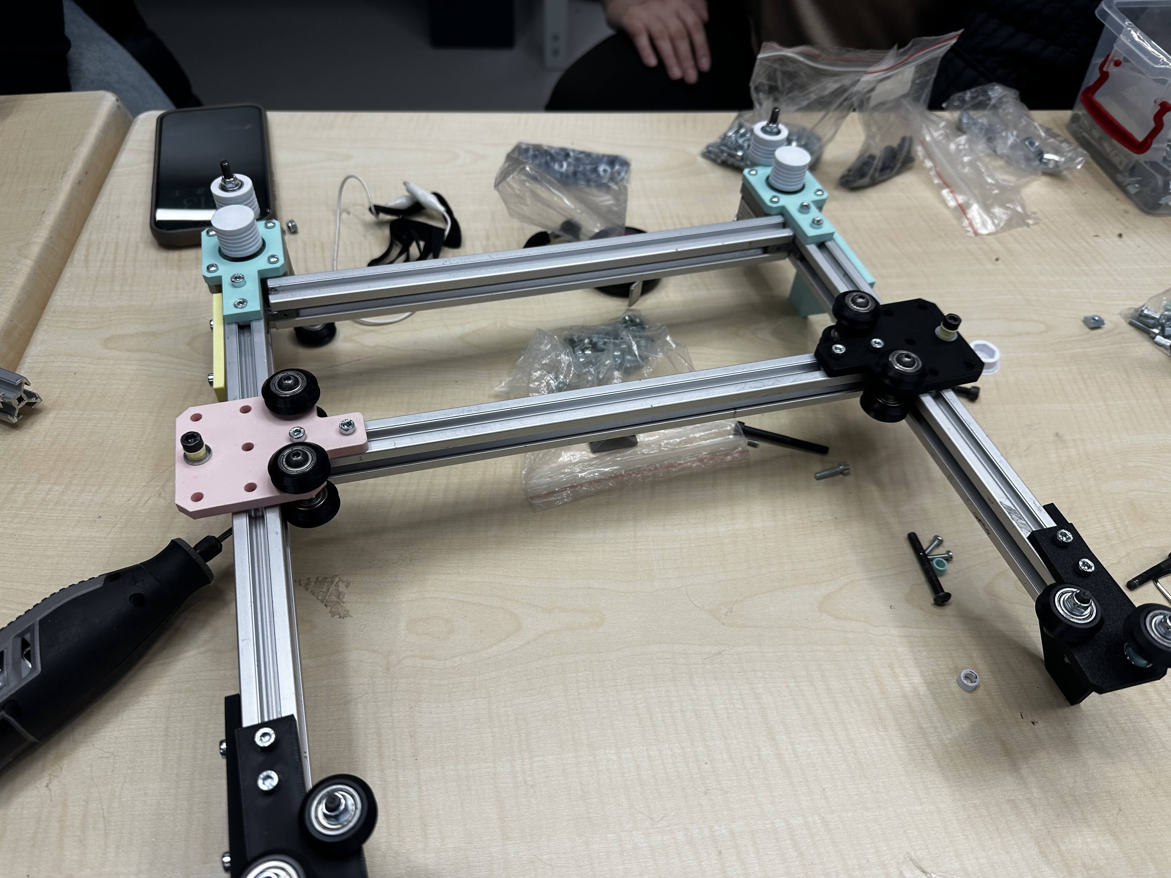
At this point, the structure was assembled and visually checked as a baseline condition before final threading and movement tests. I like doing this pause-and-check stage. It gives me a clear reference state, so if a problem appears after threading I can isolate the cause faster.
7) Middle-axis manual movement test
I performed a manual motion test on the middle-axis section. In the observed travel range, movement looked continuous without obvious sticking. I did this slowly by hand on purpose to feel resistance directly. That tactile feedback tells me things that video alone sometimes hides.
8) Thread insertion and routing setup
I inserted and aligned the thread path by hand. This step was used to verify that routing remained seated while handling and tensioning. This is where I had to stay patient. Tiny routing mistakes are easy to make, so I kept checking each segment before moving to the next one.
9) Middle-axis test with thread installed
After installing the thread, I repeated movement checks to see if tension/path introduced instability. In the clip, the thread remains seated during motion. I was specifically watching for sudden jumps and uneven pull. Seeing stable tracking here was a big confidence boost before the final run.
10) Final full movement test
I completed a final movement test on the assembled mechanism. Across the visible range in the clip, carriage motion appears smooth and controllable. This final test felt rewarding because it connected all the earlier micro-decisions. The system moved the way I expected, which confirmed that the CAD and assembly choices were mostly correct.
Problems and fixes
Problem: Thread routing can become inconsistent if early alignment is loose.
Fix: I added early fit checks (groove fit + local motor mount routing test) before full threading.
Problem: Dynamic issues are harder to diagnose after full assembly.
Fix: I used staged validation (local check -> middle-axis check -> full movement check).
Result
The Core-XY mockup reached a working mechanical state for pen plotter preparation:
- frame assembled and stable,
- thread path installed and seated,
- movement tests completed with acceptable smoothness in observed clips.
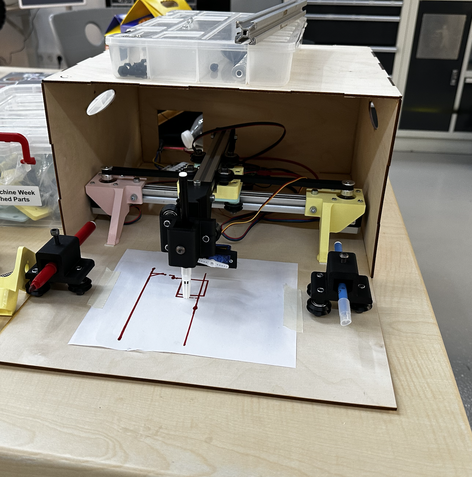
After
After this mockup which I was mainly responsible for we moved onto the plotter and produced the final machine below
Reflection
For the first time I assembled a mechanical system and understood how the core xy system work in real life I also learned that good machine building is mostly about consistency: small checks, small corrections, and repeating tests until behavior becomes predictable. This week made me much more comfortable with the bridge between CAD intent and physical motion. It improved both my physical skills in assembly and also machine design.