Week 04 - Embedded programming
Overview
This week, I focused on trying different workflows. Even though I had not worked deeply in this area before, I wasn’t familiar with the basics. I decided to start with digital work first and then move to physical implementation. Before designing anything, I reviewed several microcontroller datasheets, especially the Raspberry Pi Pico and its RP2040 chip.
Understanding the Datasheet
Before designing or programming a board, it is very important to understand the microcontroller by reading its datasheet. For this week I mainly studied the RP2040 datasheet to learn about its features, limits, and structure. This helped me make better design and programming decisions.
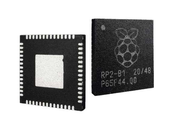
Raspberry Pi Pico Basics
The Raspberry Pi Pico is a small development board built around the RP2040 microcontroller. It is designed to be low-cost, flexible, and easy to use.
Main features:
- Dual-core ARM Cortex-M0+ (up to 133 MHz)
- 264 KB SRAM
- 2 MB external flash memory
- USB 1.1 support
- 26 multi-function GPIO pins (3 ADC pins)
- Small size: 51 × 21 mm
Because of these features, the Pico is suitable for many embedded projects.
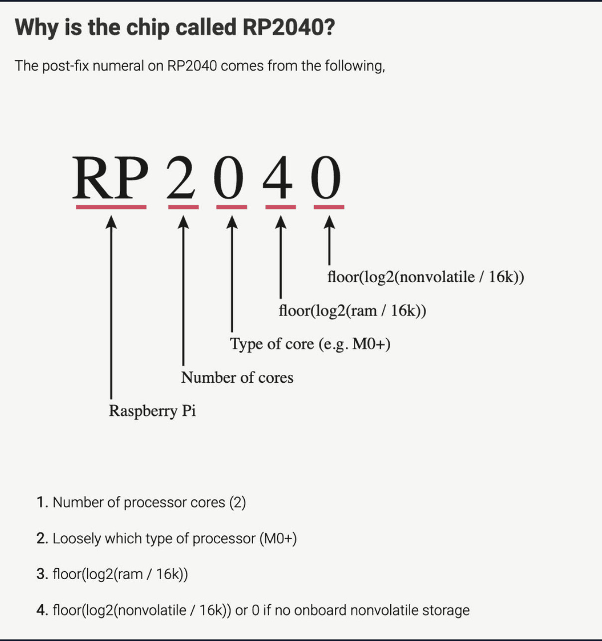
Meaning of the Name RP2040
The name RP2040 is not random. Each part represents a feature of the chip:
- RP → Raspberry Pi
- 2 → Two processor cores
- 0 → Cortex-M0 class processor
- 4 → RAM size category
- 0 → No built-in flash memory
So, the name gives basic information about the chip.
**Internal Structure
The RP2040 consists of several important parts:
- Two processor cores
- Clock system with PLLs
- GPIO and peripheral controllers
- PIO blocks for custom protocols
- SRAM and boot ROM
- QSPI interface for external flash
- USB controller
- Internal bus system
These components work together to manage data, memory, and peripherals efficiently.
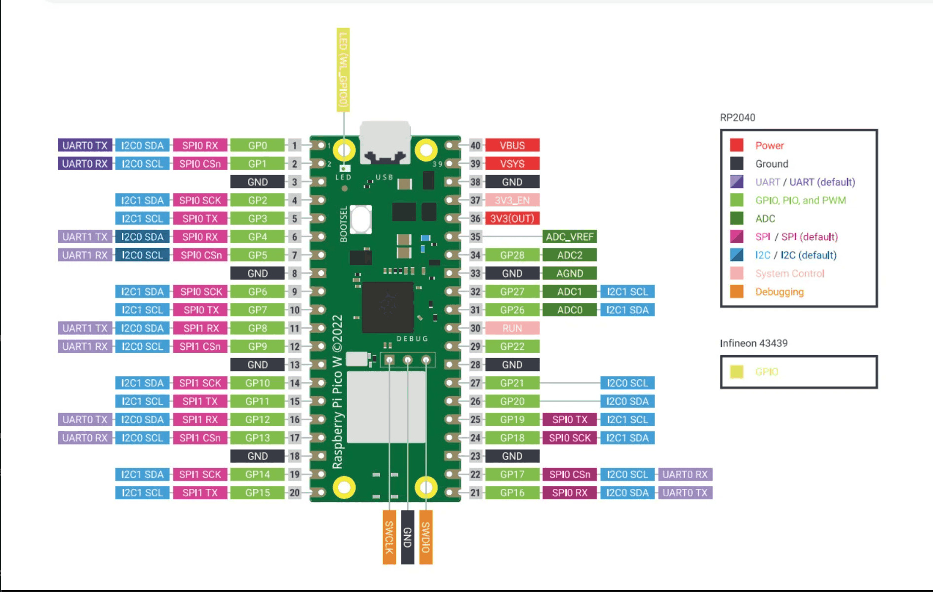
Pins and Their Functions
The Pico provides 26 usable GPIO pins. Some pins are reserved for special purposes:
- GPIO25 → Onboard LED
- GPIO24 → USB voltage detection
- GPIO29 → Voltage monitoring
- GPIO23 → Power control
Important power-related pins:
- VBUS → USB power (5V)
- VSYS → Main power input
- 3V3 → Regulated output
- RUN → Reset pin
- AGND → Analog ground
ADC Characteristics
The ADC uses the 3.3 V supply as reference, which causes:
- Some electrical noise
- Small voltage offset
- Input voltage limit: max 3.6 V
For accurate measurements, this must be considered.
Programming and Debugging
The Pico supports easy programming and debugging:
- BOOTSEL button for drag-and-drop programming
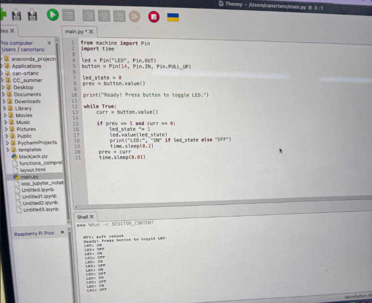
- The main programming and debugging are getting done by Thonny.
- USB mass storage bootloader
- SWD debugging interface
These features make development simple for beginners.
Physical Dimensions
- Size: 51 × 21 mm
- Thickness: 1 mm
- Castellated edges for soldering
Thanks to this design, the Pico can be mounted directly onto custom PCBs.
Performance Comparison
Compared to older and modern devices, the RP2040 offers good performance for embedded systems.
Examples:
- Much faster than old computers like Apple II
- More powerful than ESP8266
- Less powerful than Raspberry Pi 3, 4, and 5
- Well-balanced for low-power projects
It provides strong performance for microcontroller-based applications.
The Codding
Importing The Required Modules
from machine import Pin
import time
- Pin allows us to control GPIO pins.
- time is used for delays (debouncing).
Initializing LED and Button
led = Pin("LED", Pin.OUT)
button = Pin(14, Pin.IN, Pin.PULL_UP)
- The built-in LED is configured as an output.
- The button is configured as an input with an internal pull-up resistor.
Initializing State Variables
led_state = 0
prev = button.value()
- led_state stores whether the LED is ON (1) or OFF (0).
- prev keeps track of the previous button state for edge detection.
Main Loop
while True:
- The program runs continuously.
Detecting The Button Press
curr = button.value()

if prev == 1 and curr == 0:
Because we are using a pull-up resistor:
- Button not pressed → 1
- Button pressed → 0 We detect the transition from 1 → 0, which means the button was just pressed and this prevents multiple toggles while holding the button.
Toggle LED State
led_state ^= 1
This uses the XOR operator (^=) to toggle the value:
- If led_state is 0, it becomes 1
- If led_state is 1, it becomes 0 This is a compact way to switch between on and off.
Update LED Output
led.value(led_state)
Now the LED is set to a new state.
Open Close Delay
time.sleep(0.2)
This prevents multiple rapid triggers caused by mechanical button bouncing.
Update Previous State
prev = curr
time.sleep(0.01)
- Store the current button state for the next loop
- Small delay to reduce CPU usage
Here are my normal and final outputs from my pico. This photo is to light the “LED” part of the Pico Board:
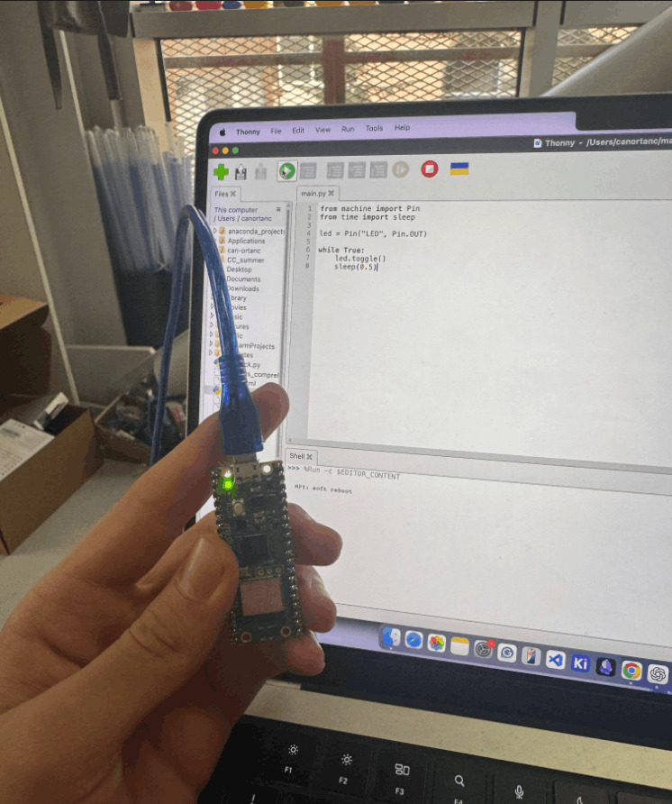
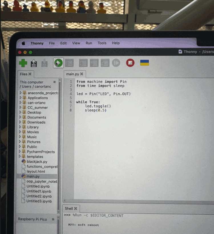
The code for to light the “LED” part at the board that i showed:
And here is the final part where I lit the “LED” part with a button that I added extensionally with the help of the breadboard:

Finally, here is the code that I wrote in Thonny that has been used for to light the “LED” with an extra button: