# Practical Programming and Board Testing
For the second part of Week 4, I moved from datasheet research into hands-on programming and testing. Currently, I have several boards available for testing, including an Arduino Uno and a Seeed XIAO ESP32C3. I also plan to use the remaining boards with the Wokwi emulator.
I am more familiar with the Arduino ecosystem, so this was a good opportunity to refresh my knowledge.
## Arduino Uno R3
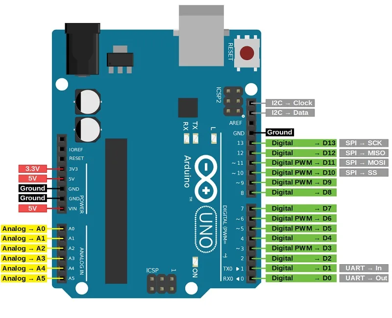
Arduino Uno R3 is a classic board built around the ATmega328P chip.
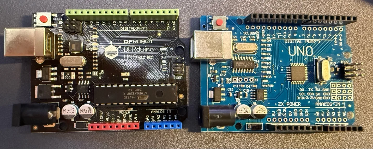
As many different projects exist with the Arduino Uno, and there is a wide range of possibilities to add extension boards and other components, I decided to focus on the basic functions and pinout first.
More documentation:
-
## Arduino IDE
For the Arduino family, many IDEs can be used, but the most direct option is the native Arduino IDE. I reviewed the main parts of the interface before starting the tests.
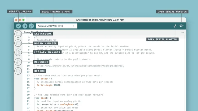
- **Verify / Upload**: checks the code for errors and uploads it to the selected Arduino board.
- **Select Board & Port**: lets me choose the board and the serial port.
- **Open Serial Monitor**: opens a window for live text data from the board.
- **Sketchbook**: gives quick access to saved Arduino projects.
- **Board Manager**: installs and manages support packages for different boards.
- **Library Manager**: installs and updates Arduino libraries.
- **Debugger**: helps inspect a program while it is running, if the board supports debugging.
- **Search**: quickly finds words or code inside the current sketch.
- **Open Serial Plotter**: shows incoming serial data as a live graph.
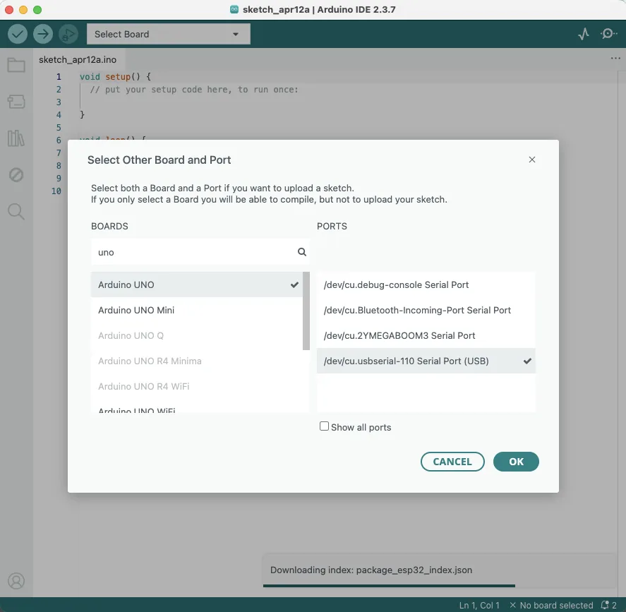
To start smoothly, I selected the Arduino Uno board and then chose the port where my board was connected, usually `USB Serial`.
## Blinking LED
As suggested, it is good to begin with a simple example such as blinking an LED or reading a button. I started with the standard blink example.
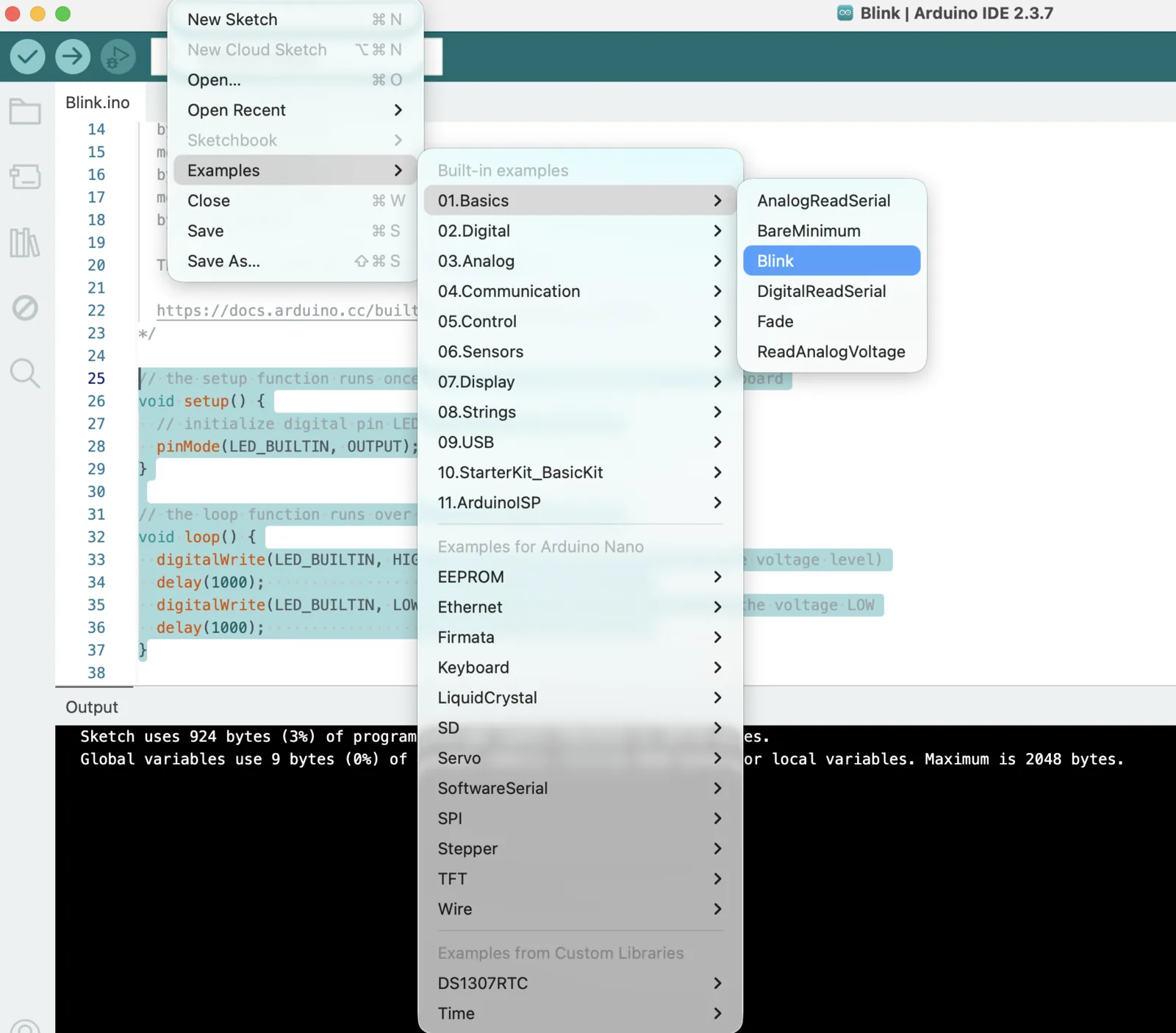
This code helped me blink the built-in LED on the Arduino board:
```cpp
// the setup function runs once when you press reset or power the board
void setup() {
// initialize digital pin LED_BUILTIN as an output.
pinMode(LED_BUILTIN, OUTPUT);
}
// the loop function runs over and over again forever
void loop() {
digitalWrite(LED_BUILTIN, HIGH); // turn the LED on
delay(1000); // wait for a second
digitalWrite(LED_BUILTIN, LOW); // turn the LED off
delay(1000); // wait for a second
}
```
As a result, the built-in LED blinked correctly on the board.
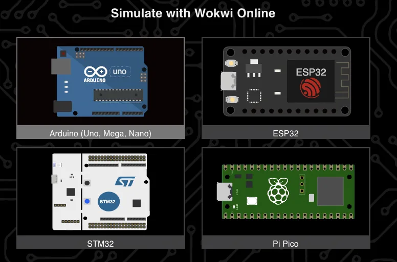
## Wokwi Emulation
For Arduino and several other boards, it is also possible to use emulation in Wokwi.
-
I uploaded the same blink code into the simulation and got the same result there as well.
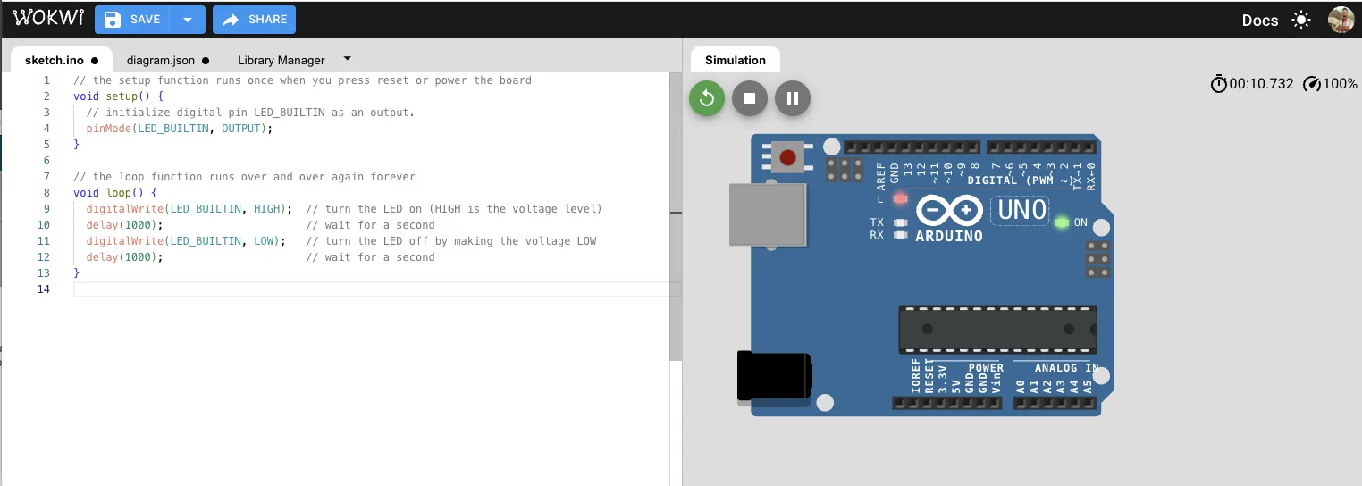
As a result, the built-in LED also blinked correctly in emulation.
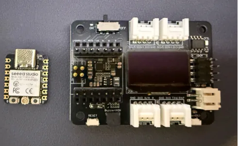
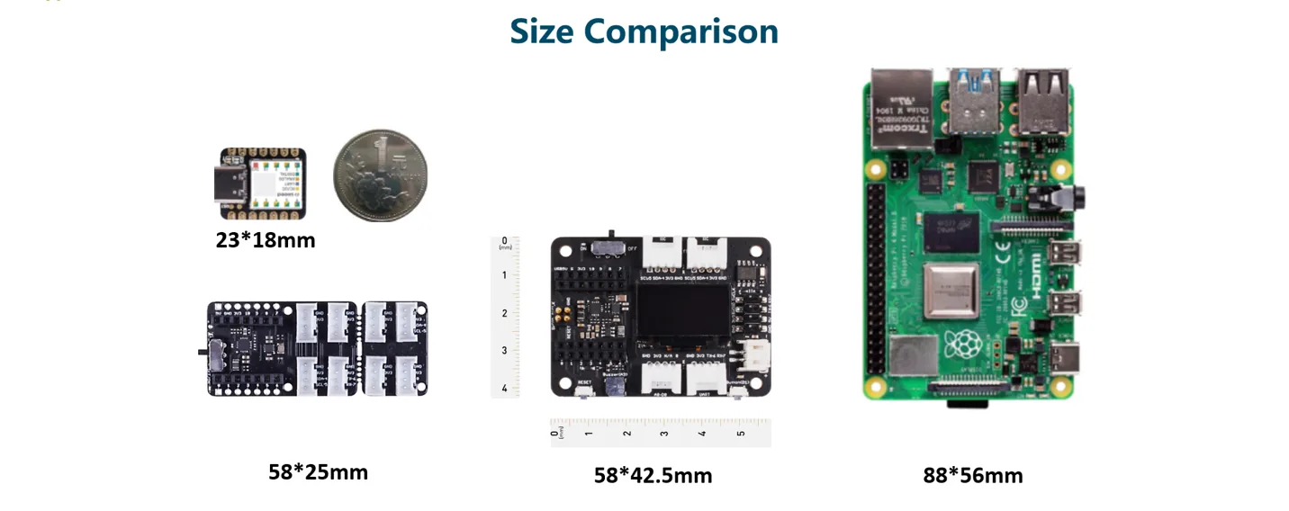
## Seeed XIAO ESP32C3 + Expansion Board
My second test platform was the Seeed XIAO ESP32C3 together with the expansion board.
It is always good to start a new board by reading the official documentation first.
- XIAO ESP32C3 getting started:
- XIAO Expansion Board:
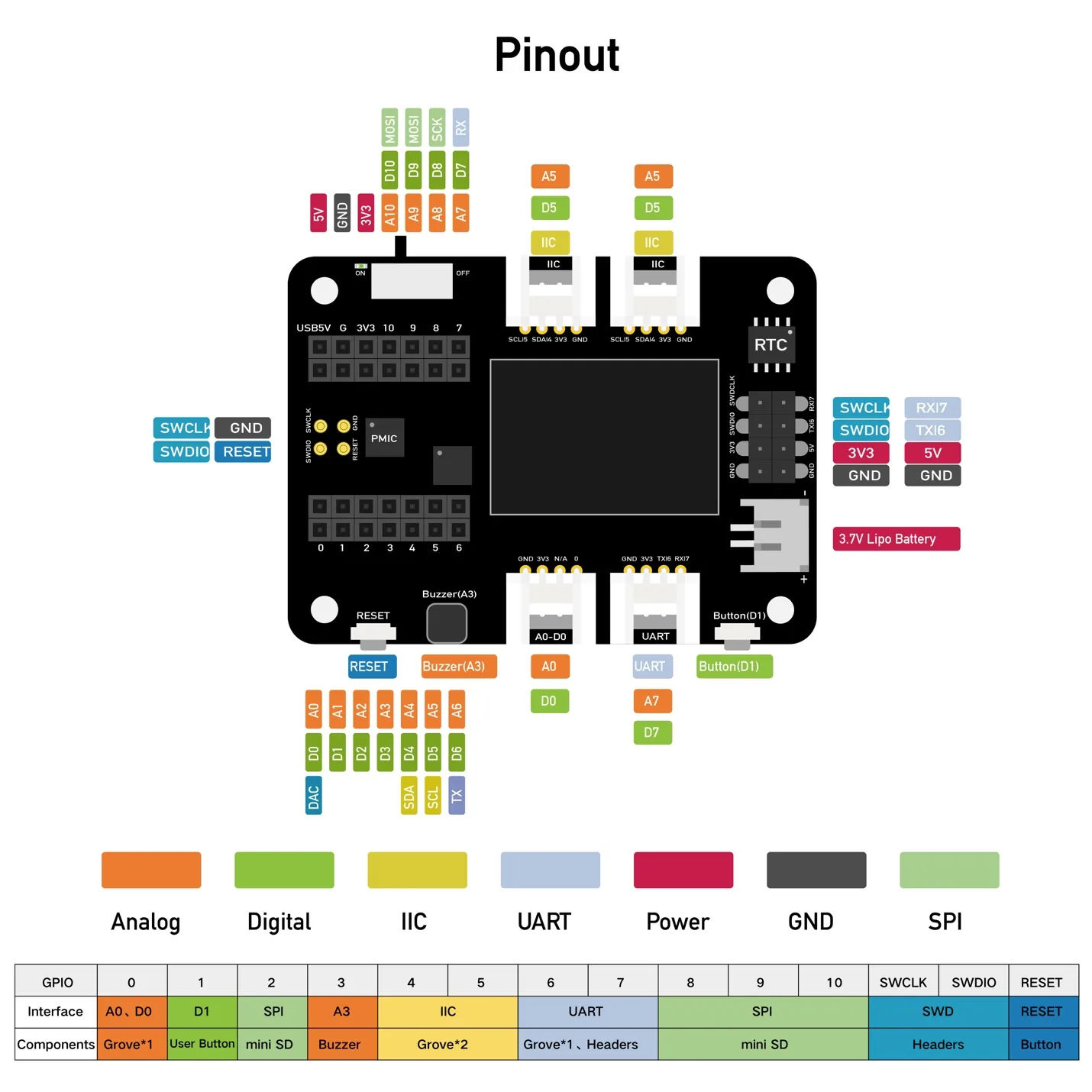
### Hardware Overview
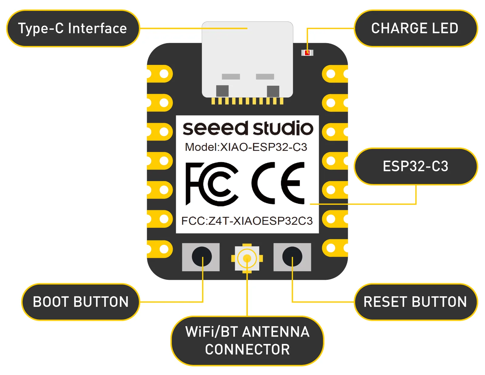
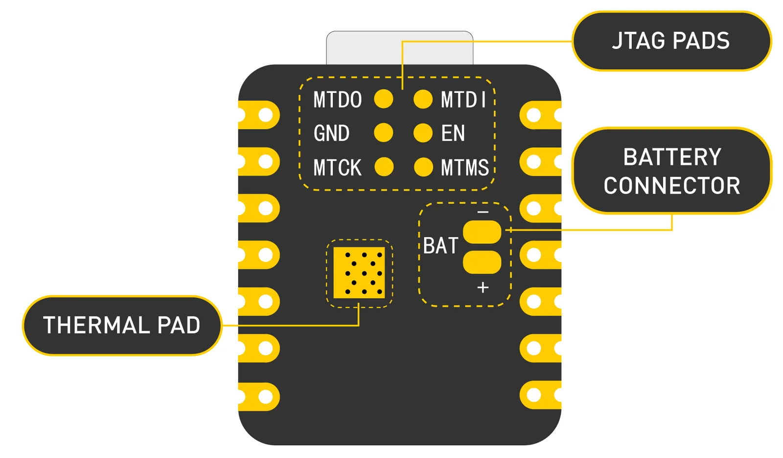
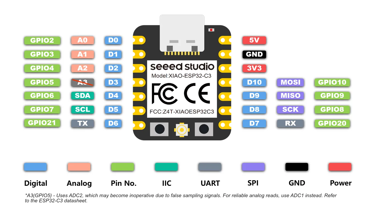
Some key power pins:
- **5V**: 5V output from the USB port. It can also be used as a voltage input with proper protection.
- **3V3**: regulated output from the onboard regulator.
- **GND**: common power, data, and signal ground.
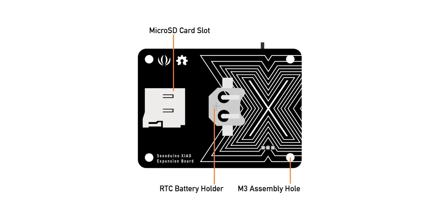
### Expansion Board
The expansion board adds several useful peripherals and makes quick testing easier.
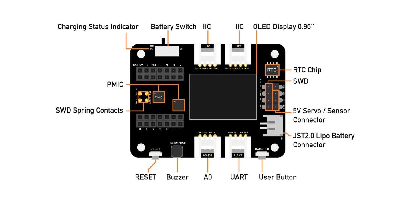
The board includes an external MicroSD card slot and an RTC battery holder. The MicroSD card can be useful for extra storage, and the RTC keeps accurate time when the main power is off.
Main expansion board specifications:
- **Operating voltage**: 5V / 3.7V lithium battery
- **Charging current**: 460 mA max
- **RTC timer precision**: +/- 1.5 s/day at 25 C
- **RTC battery**: CR1220
- **Display**: 0.96 inch OLED
- **Expandable memory**: MicroSD card
- **Grove interface**: Grove I2C x2, Grove UART x1, A0/D0 Grove x1
- **Other external equipment**: passive buzzer, user button, 5V servo connector
Modules available on the expansion board include:
- **OLED display** for quick visual feedback without needing the computer.
- **Reset button** for easier board reset.
- **SWD debug pins** for easier debugging and firmware download.
- **High-precision RTC** with battery backup.
- **MicroSD slot** for expanded storage.
- **User button** for custom input.
- **Passive buzzer** for simple sound output.
- **Grove connectors** for plug-and-play modules.
- **LiPo battery charging** support.
- **5V servo connector** for servo and sensor connection.
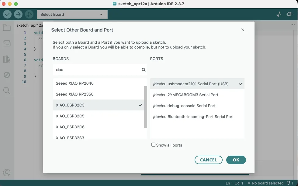
## Board Programming
For the XIAO ESP32C3, I could still work in the Arduino IDE, but I needed to select the correct XIAO board package and the correct port, usually a USB modem port.
After the board was connected and recognized, I used the OLED display example from the official documentation. For the display, I also needed to install the `U8g2` library from the Arduino Library Manager.
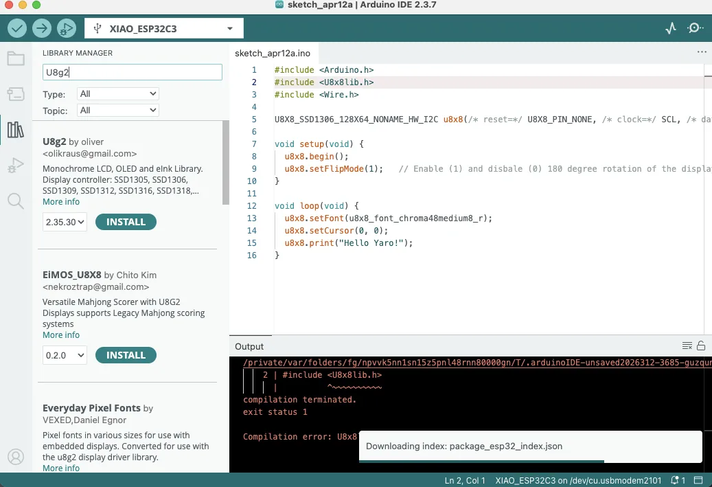
The first OLED test code was:
```cpp
#include
#include
#include
U8X8_SSD1306_128X64_NONAME_HW_I2C u8x8(
/* reset = */ U8X8_PIN_NONE,
/* clock = */ SCL,
/* data = */ SDA
);
void setup(void) {
u8x8.begin();
u8x8.setFlipMode(1); // enable 180 degree rotation
}
void loop(void) {
u8x8.setFont(u8x8_font_chroma48medium8_r);
u8x8.setCursor(0, 0);
u8x8.print("Hello Yaro!");
}
```
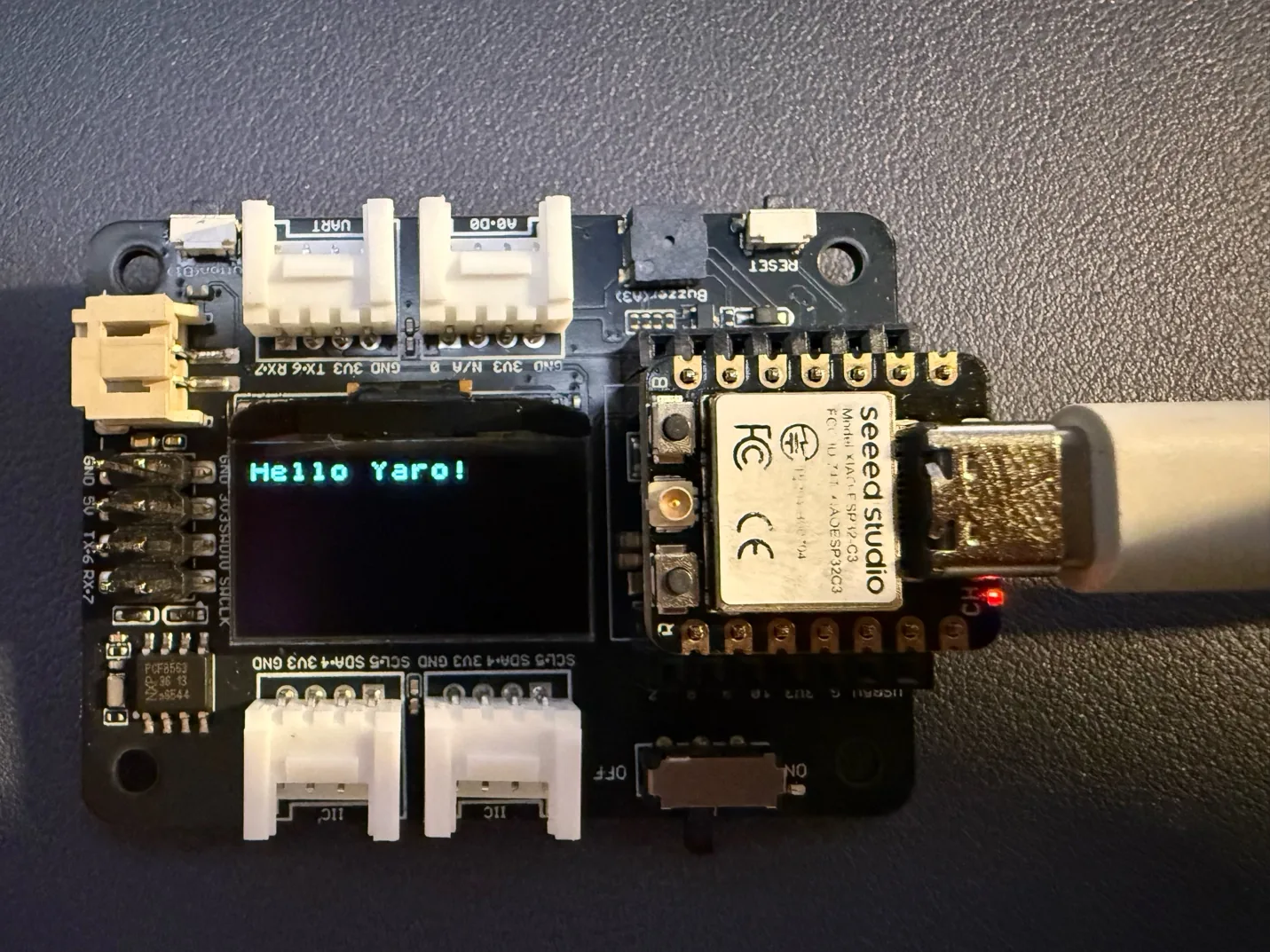
As a result, I could see the text on the OLED screen mounted on the expansion board.
## OLED + RGB LED Experiment
After that, I asked AI to extend the example. I wanted to use a 30-LED strip instead of 8 LEDs, create a running gradient effect, and add more interesting graphics to the screen for testing.
In Arduino IDE, I also installed:
- **Adafruit NeoPixel**
The resulting sketch was:
```cpp
#include
#include
#include
#include
#define LED_PIN D0
#define LED_COUNT 30
U8G2_SSD1306_128X64_NONAME_F_HW_I2C u8g2(U8G2_R0, U8X8_PIN_NONE);
Adafruit_NeoPixel strip(LED_COUNT, LED_PIN, NEO_GRB + NEO_KHZ800);
int shipX = 10;
int dir = 1;
int ledHead = 0;
void drawShipScene() {
u8g2.clearBuffer();
for (int i = 0; i < 20; i++) {
int x = (i * 23 + millis() / 10) % 128;
int y = (i * 13 + millis() / 20) % 64;
u8g2.drawPixel(x, y);
}
u8g2.setFont(u8g2_font_6x12_tf);
u8g2.drawStr(18, 10, "OLED + RGB TEST");
u8g2.drawTriangle(shipX, 50, shipX + 12, 50, shipX + 6, 38);
u8g2.drawPixel(shipX + 4, 52);
u8g2.drawPixel(shipX + 8, 52);
u8g2.sendBuffer();
}
void updateLEDs() {
strip.clear();
for (int t = 0; t < 8; t++) {
int p = ledHead - t;
if (p >= 0 && p < LED_COUNT) {
int b = 255 - t * 30;
if (b < 0) b = 0;
strip.setPixelColor(p, strip.Color(0, 0, b));
}
}
strip.setPixelColor((ledHead + 10) % LED_COUNT, strip.Color(0, 150, 0));
strip.setPixelColor((ledHead + 20) % LED_COUNT, strip.Color(150, 0, 0));
strip.show();
ledHead++;
if (ledHead >= LED_COUNT + 8) ledHead = 0;
}
void setup() {
u8g2.begin();
strip.begin();
strip.setBrightness(80);
strip.clear();
strip.show();
}
void loop() {
shipX += dir;
if (shipX < 5 || shipX > 110) dir = -dir;
drawShipScene();
updateLEDs();
delay(60);
}
```
### Very Simple Explanation of the Code
This program uses the **OLED screen** and the **RGB LED strip** together. The screen shows a small moving spaceship with stars in the background, while the LED strip shows moving colored lights. In `setup()`, the screen and LED strip are started. In `loop()`, the spaceship moves left and right, the screen is redrawn, and the LED animation updates repeatedly.
Very brief function explanations:
- **`drawShipScene()`**: clears the OLED screen, draws moving stars, writes the title text, and draws the spaceship.
- **`updateLEDs()`**: clears the LED strip and creates a moving light effect with blue, green, and red LEDs.
- **`setup()`**: starts the OLED display and LED strip, sets brightness, and turns LEDs off at the beginning.
- **`loop()`**: moves the spaceship, changes direction at the edges, then updates both the screen and the LED strip.
Very brief variable explanations:
- **`LED_PIN`**: defines which pin is connected to the LED strip.
- **`LED_COUNT`**: defines how many LEDs are in the strip.
- **`shipX`**: stores the horizontal position of the spaceship.
- **`dir`**: controls whether the spaceship moves left or right.
- **`ledHead`**: controls the moving position of the LED light effect.
As a result, the OLED screen showed simple moving graphics and the LED strip displayed a moving multicolor light effect.
## Video
## Reflection
This week, as part of Week 4 of Fab Academy, I explored different embedded systems and microcontrollers in both virtual and real programming environments. I worked with Arduino Uno in simulation and in real hardware, and I also programmed the Seeed Studio XIAO ESP32C3. This helped me understand the difference between testing code virtually and applying it to actual physical devices.
During this week, I connected and programmed several components, including an RGB LED strip and the display on the XIAO expansion board. I also used AI to help me write code, improve it, and understand it better. This was especially useful when I was learning something new, because it helped me break the code into smaller parts and understand what each function was doing. With this support, I was able to make the code easier to follow and more structured.
This week showed me that embedded programming is not only about writing code, but also about understanding how software interacts with hardware. I had to solve practical problems, test different ideas, and learn through experimentation. Using AI as a support tool made this process more effective because it helped me understand the logic behind the code rather than only copying it.