Output Devices
Week 10
- Measure the power consumption of an output device.
- Document the group work on the group work page and reflect on the individual page what was learned.
Power Consumption
The objective of this activity was to measure the power consumption of an electronic device. To calculate power, we used the following formula:
P = V x I
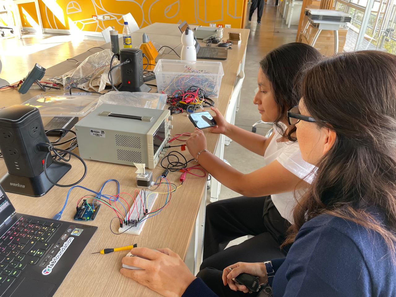
For this exercise, we measured and compared the power consumed by a stepper motor when it was powered on but stopped, and when it was moving. We used a GW INSTEK GPD-3303D power supply and implemented an Arduino UNO-based circuit.
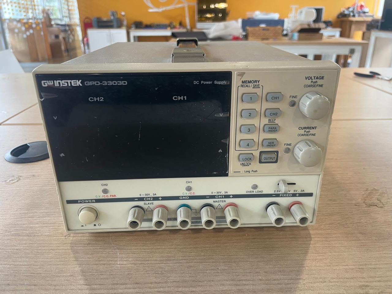
GW INSTEK GPD-3303D
Main Technical Specifications
- Channels: 3 independent and isolated channels.
- Main channels (1 and 2): 0 to 30 V and 0 to 3 A.
- Third channel: selectable fixed output of 2.5 V, 3.3 V, or 5 V, with a maximum current of 3 A.
- Resolution: high resolution of 1 mV and 1 mA.
- Operating modes: independent, series, or parallel, allowing up to 60 V or 6 A by combining channels.
- Total power: 195 W.
Main Features
- Digital control and LED display: allows accurate voltage and current configuration and clear parameter readings.
- Connectivity: includes a standard USB interface for remote control from a computer.
- Memory: allows storing and loading up to 4 different user configurations.
- Smart cooling: temperature-controlled cooling fan to reduce noise.
Stepper Motor Control Circuit
We assembled the following circuit to control a stepper motor. The components used were:
- Arduino UNO
- DRV8825 stepper motor driver
- NEMA 17 stepper motor
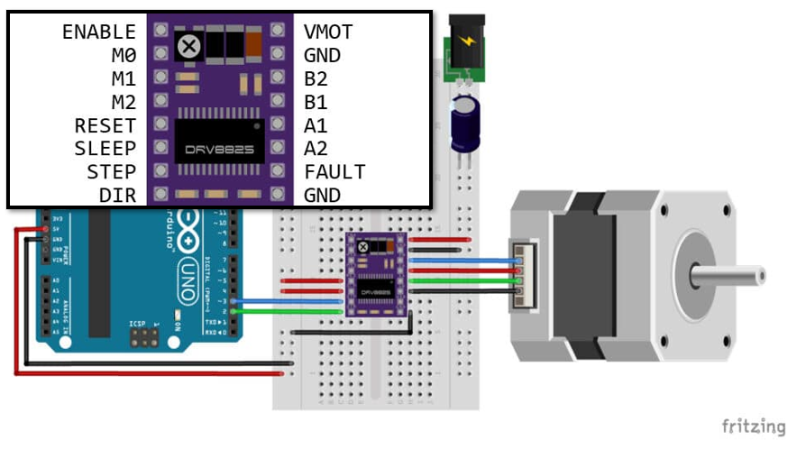
The following image shows the implemented circuit:
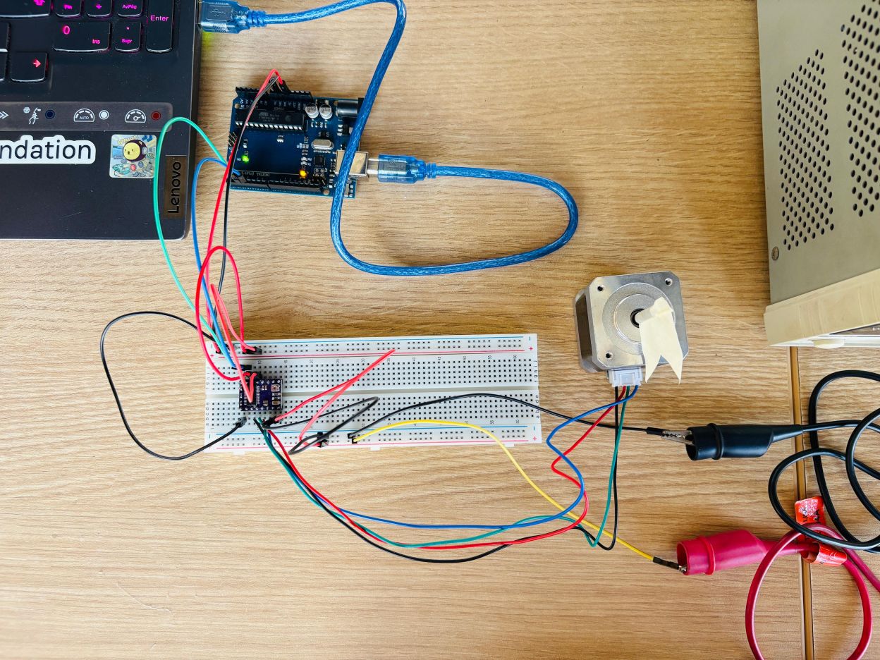
Expanded view of the circuit connections with the laptop and the power supply:
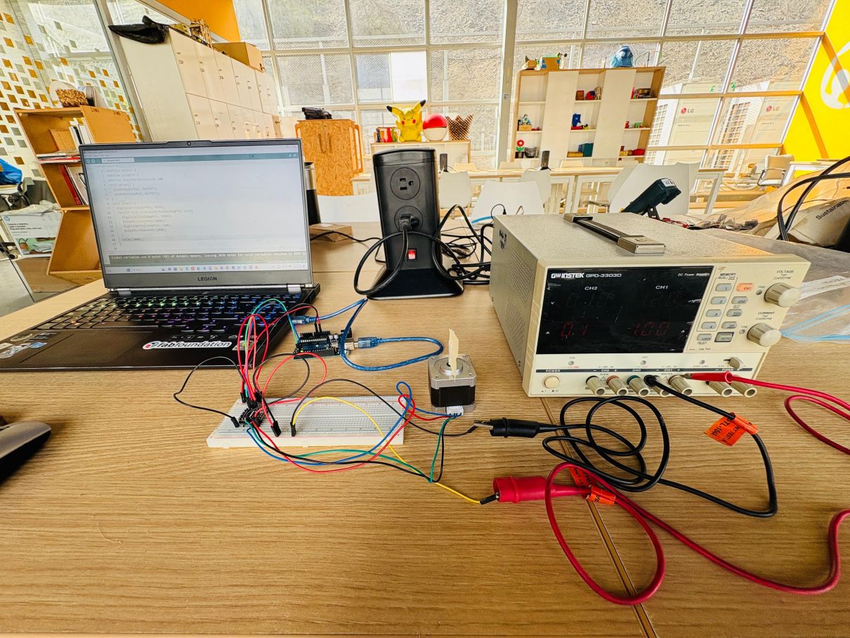
Arduino Code
#define dirPin 2
						#define stepPin 3
						#define stepsPerRevolution 200

						void setup() {
						pinMode(dirPin, OUTPUT);
						pinMode(stepPin, OUTPUT);
						}

						void loop() {
						digitalWrite(dirPin, HIGH);

						for (int i = 0; i < stepsPerRevolution * 5; i++) {
							digitalWrite(stepPin, HIGH);
							delayMicroseconds(2000);
							digitalWrite(stepPin, LOW);
							delayMicroseconds(2000);
						}

						delay(5000);
						}
Measurements and Results
The voltage was set to 12.0 V. The current was read directly from the power supply in each operating condition, and the power was calculated using P = V x I.
| State | Voltage (V) | Current (mA) | Power (W) |
|---|---|---|---|
| Motor stopped | 11.9 | 0.23 | 2.74 |
| Motor moving | 11.9 | 0.37 | 4.40 |
Test Video