Electronics Design
Week 06
Logic Analyzer and UART Signal Measurement
What is a Logic Analyzer?
A logic analyzer is an instrument used to capture, display, and measure multiple electronic signals simultaneously in a digital circuit. It allows us to observe the timing relationship between different digital signals and is especially useful for analyzing communication protocols such as I2C, SPI, and Serial/UART. For this reason, it is one of the most useful tools for debugging digital circuits and communication systems.
Reference: Saleae - What Is a Logic Analyzer?
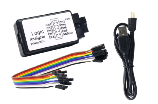
For this assignment, we used an 8-channel USB logic analyzer with a Mini USB cable and jumper wires. The model used was the LA-24MHz-8CH, compatible with the Saleae driver.
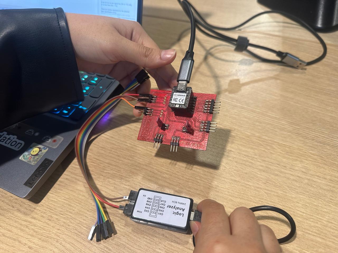
In the Fab Lab, we were provided with a board based on the XIAO RP2040. Using this board, we generated a digital output on pin D0 and a serial communication signal using pins D1 (TX) and D2 (RX).
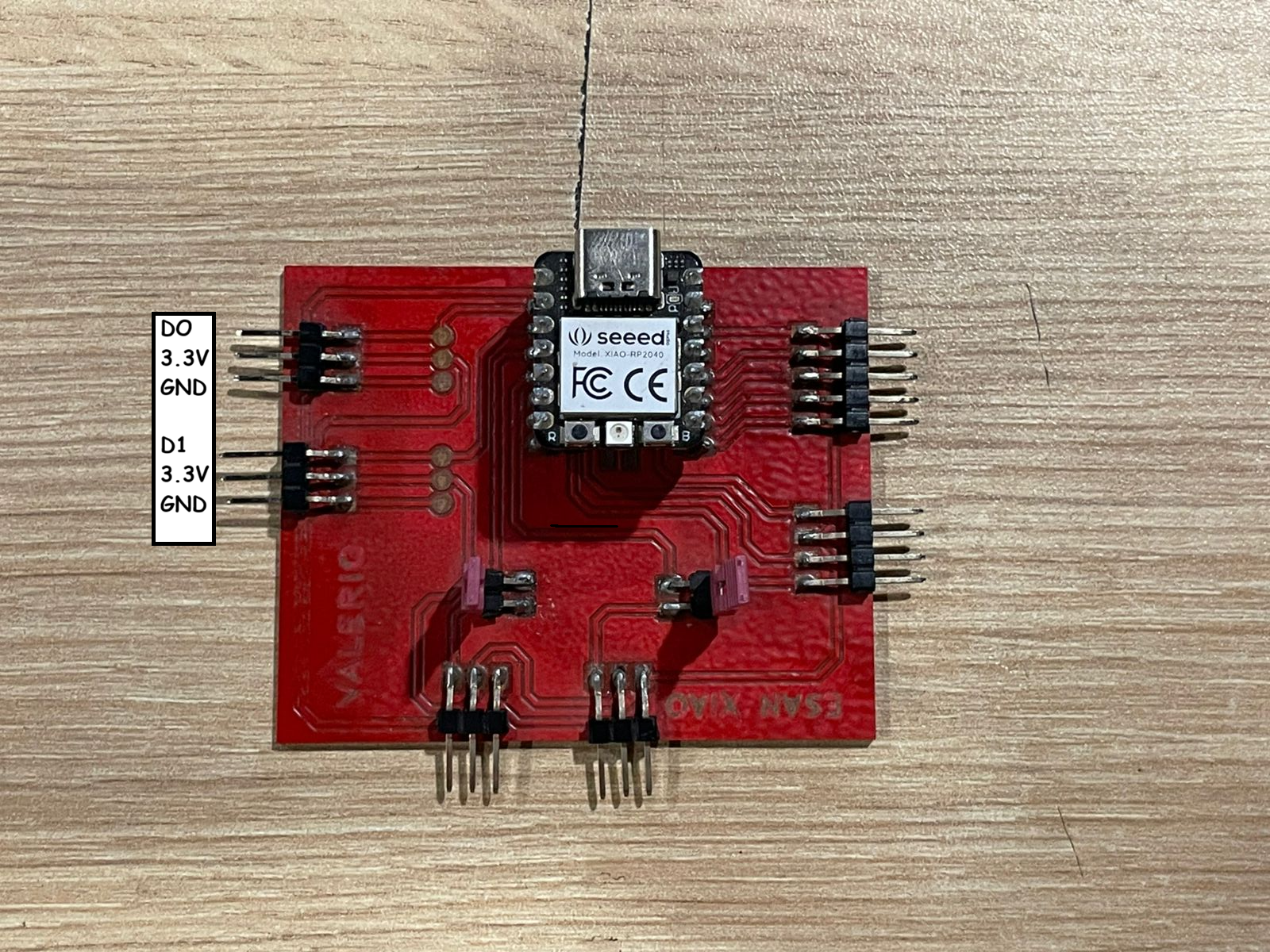
Wiring
The pins were connected as shown below:
| XIAO RP2040 | Logic Analyzer |
|---|---|
| D0 | CH1 |
| D1 | CH2 |
| GND | GND |
Arduino Code
In Arduino IDE, we wrote the following code for the XIAO RP2040. The program generates a digital pulse on pin D0 and sends the message FabAcademy 2026 through pin D1 using a software serial port.
						#include <SoftwareSerial.h>
						#define pinOut D0 // Digital output

						SoftwareSerial mySerialPort(D2, D1); // RX, TX

						void setup() {
						Serial.begin(9600);
						mySerialPort.begin(9600);
						pinMode(pinOut, OUTPUT);
						}

						void loop() {
						mySerialPort.write("FabAcademy 2026"); // Sending a message

						// Generating a digital pulse
						digitalWrite(pinOut, HIGH);
						delay(1000);
						digitalWrite(pinOut, LOW);
						delay(1000);
						}
PulseView Configuration
We installed PulseView for Windows from the following link: https://sigrok.org/wiki/Downloads.
After connecting the USB logic analyzer, PulseView automatically detected the device as Saleae Logic.
The capture settings were configured as follows:
- Samples: 100K samples
- Frequency: 50 kHz
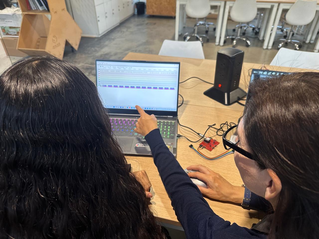
Then, we started the acquisition by pressing the Run button and zoomed in to analyze the captured signals.
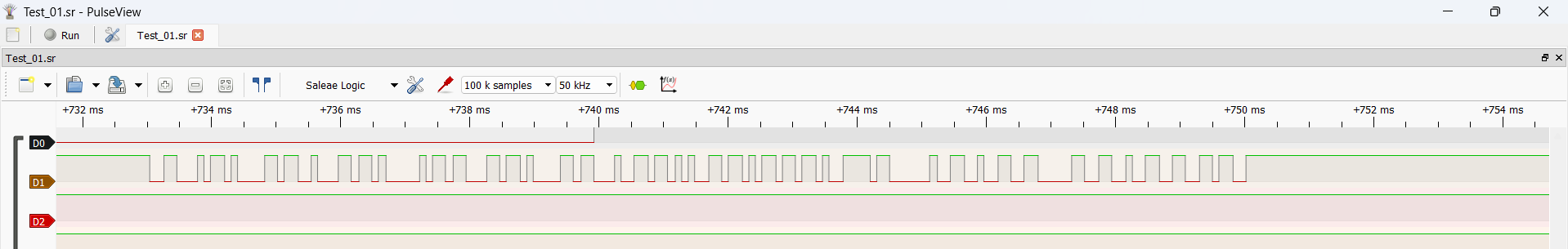
Signal Analysis
In channel 0, we could observe the digital pulse generated by pin D0. We could also observe the serial message transmitted through pin D1.
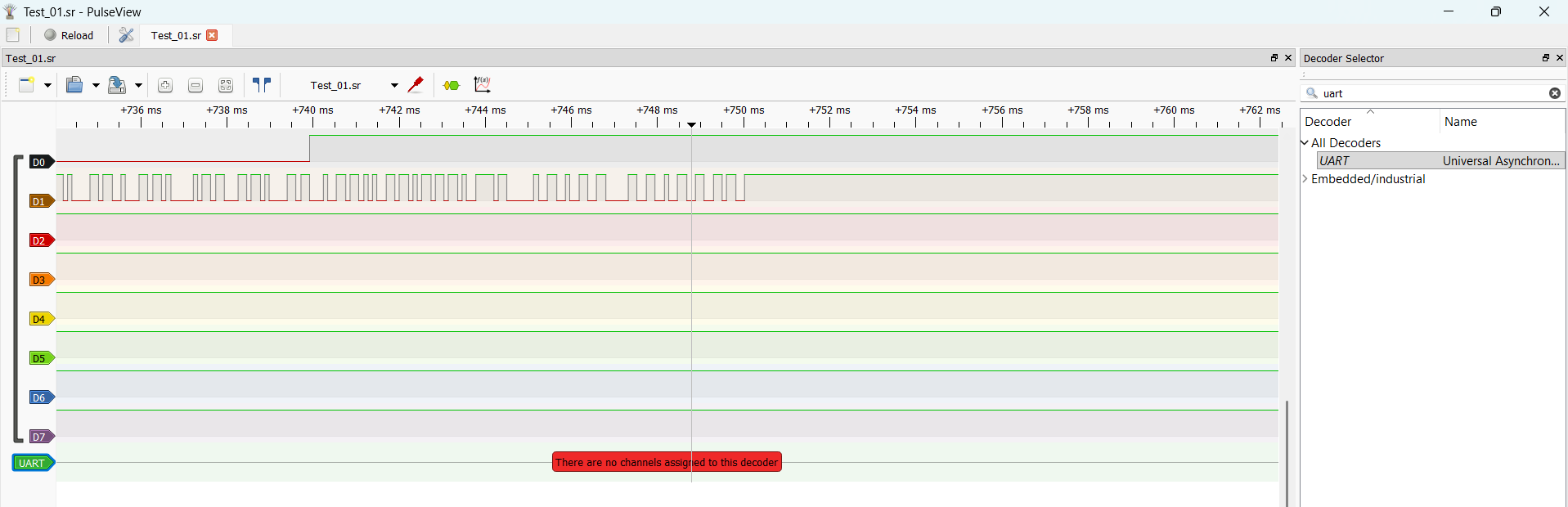
To decode the message generated by the serial port, we added a protocol decoder from the toolbar and selected the UART protocol.
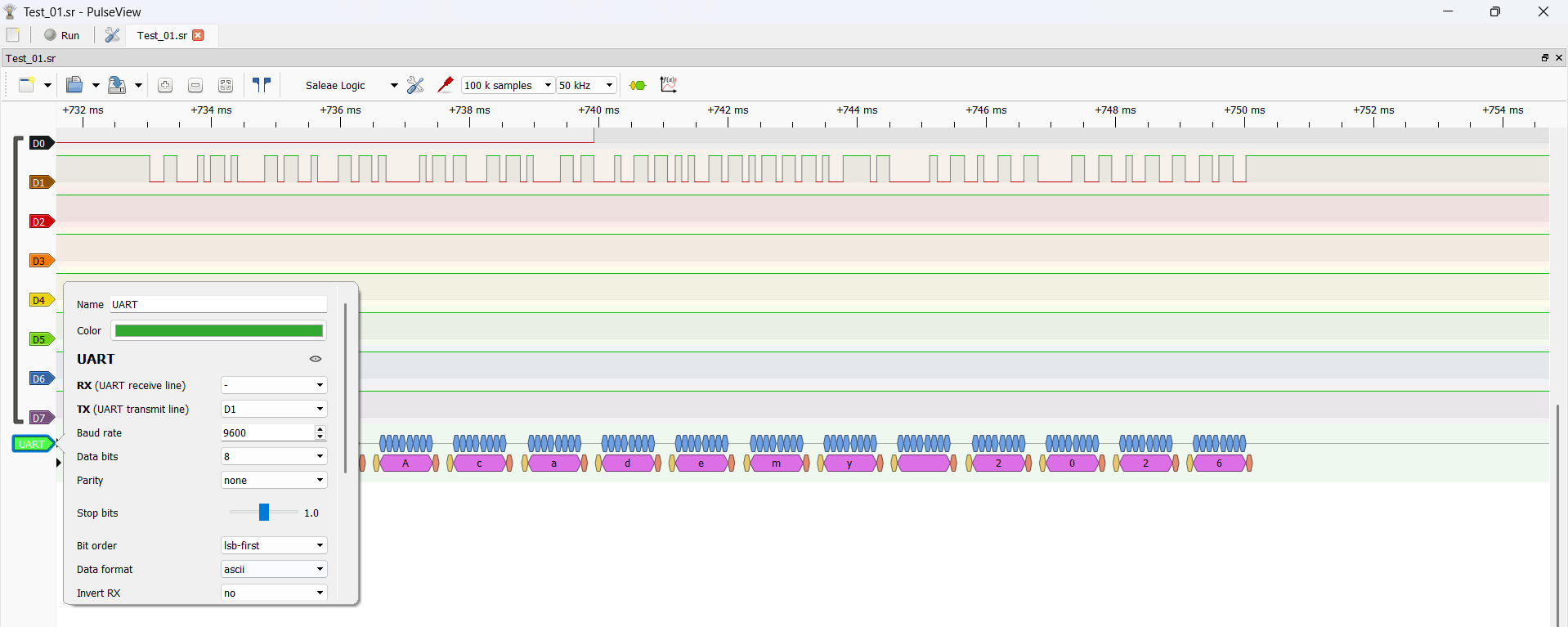
To display the message in ASCII format, we configured the UART decoder by double-clicking on the UART channel and setting the following parameters:
- TX (UART transmit line): D1
- Baud rate: 9600
- Data format: ASCII
Conclusion
With this test, we confirmed that the logic analyzer can capture both a digital pulse and a UART serial signal generated by the XIAO RP2040. PulseView allowed us to visualize the timing of the signals and decode the serial message successfully using the UART protocol decoder.