computer-controlled machining
Assignment
Group assignment:
- Complete your lab's safety training
- Test runout, alignment, fixturing, speeds, feeds, materials and toolpaths for your machine
- Document your work to the group work page and reflect on your individual page what you learned
Individual project:
-
Make (design+mill+assemble) something big
- extra credit: don't use fasteners or glue
- extra credit: include curved surfaces
- extra credit: use three-axis toolpaths
Additional Personal Goals
Brad Gun
I learned to use a Brad Gun. I did know what Brad's were, but I didn't know thier name until Dr. Taylor taught me a bunch about them. See my notes on my Brad Gun page.
Genmitsu PROVer 3018 CNC Mill
Although I didn't get to learn to use my own little CNC that I have at home. I have used it once, but would like to really understand how it works and feel comfortable using it. I do feel like I understand CNC more and was able to find a bunch of links and videos that will help me, as well as some open source software since I may not always have Fusion 360$$.
Sainsmart Start guide is quite good with lots of pictures.
Software for getting the gcode
- https://easel.com/
- https://grid.space/kiri/
Use Candle to get gcode to machine
You tube videos
I think I used this one to do my first project that I ever did with my G.
Then I just found these two I was going to try: - This tutorial came from Kiri I think as a suggested watch, but the new Kiri is version 4.??
- Fusion 360 toothpaths?
The Group Work
Link to our group page here
I Love my Pen.. Learning feeds and speeds of the wood turner was a surprise for me becuase it's something I never thought I would be using.

Most of our feeds and speeds are set by default in our shop equipment when you chose your material. I will use the testing techniques more in my personal Genmitsu at home.
The Individual Work
My asset files are here.
Figuring out what I was going to build was my first hurdle. I started by looking at what others had done. Then I was trying to think out what would be large and useful for me. I decided on a rain shield. This would be useful for trouble shooting the water in the garage and giving the doggie a shelter from the rain.
I decided to build in Fusion 360 since I don't have Aspire at home. I watched a tutorial on making a table with a shelf which talked about the tabs and press fits. They did the dog bones manually. I am going to try to use the tools in Aspire to do them.

I was going to use the drawing feature to bring out my dxf's to go to Aspire, but my computer couldn't handle it.

So then I decided to export the files every way I knew how and then bring them into the lab for discussion of best way to proceed. I exported the entire model as an STL. I exported the individual bodies as STL's. I exported the whole thing as fusion 360 file. The braces are all the same.. so I just exported one as an STL. I exported the top part as a DXF - it's just a square.. and I may make it out of plywood, acrylic, or sheet metal.. depends on what is available.
When I got to the lab, I found out that Aspire does not import STL's and is mainly a 2D program. Then I started exporting as 2D files. I wanted to check the DXF or SVG. I wanted to check the file. So I brought it into inkscape. But inscape has problems bringing in the curves. They just weren't there. This was a common issue discussed in the online chat rooms.

I was able to bring the dxf files. into Aspire using the batch command see more below.
ASPIRE Programming
To learn how to use the SHOPBot we did a small project. I made a trivet for the Queen City Robotics kitchen.

The picture is on the laser cutter becuase I late put a logo on the bottom.
KEY POINTS: - Profile -edge cut - Avoid 90 degree corners - a CNC cant make 90 corners… - Pocket - to remove alot of inside material - Engraving - to write stuff on top.. But mainly use the TEXT feature
- Toolpath - large shop bot - ⅜ compression
- Each pass, should not be more than the width of the bit
- Change edit passes to make sure its less than .375 (the size of our bit)
- Be aware of inside vs outside cut…
- Name each cut.. So you don't forget what the pass was doing.
- Last thing is save tool paths - make sure to check visible tool paths… all visible
- End up with two files - one with the file you made, and another that you have as the tool paths
I found this graphic helpful for understanding the bits. I cant remember where I got it.. maybe from class?

So I had a bit of an issue getting the correct file types for brining into Aspire. For some of my pieces, I ended up doing a projection to a new sketch so that I could bring them in as DXF files. I put all my dxf files into one folder and then I was able to use a batching file in Aspire.

I filleted all my corners at .375 in Aspire. This is the same place that I was able to get the dogbone option.

I used the dogbone with .125 - becuase the bit I am going to use for my project is 1/4 endmill. I did the dog bone on both the pocket holes of the big pieces and the end inside corners of each brace. The settings for the 1/4 end mill are below.

From makomania: T-bone and dog bone fillets are CNC techniques used to create sharp internal corners for interlocking parts by compensating for the tool's radius. Dog bones are generally stronger and better for hidden joints, while T-bones are more aesthetic and can be hidden on one side, offering a cleaner look.
Since I have hidden joints, I used dog bones.

I have thin material, .5 inches, so the bit and the small female area ended up being a bit tricky. At first the dogbone made inside circles.

but once I got the hang of it, I was able to click on teh corner when I


Originally, I was going to use a 3/8 bit to cut the braces, but as explained below it was cutting too much of the end that was going to stick into the side plates. With the original settings, I was going to cut on the outside, using two passes with a 3/8 bit — 3/8 × 2 > width of my wood, so we were good there. My cut depth is the thickness of my material.
Later using toolpaths, I changed and programmed for 3 passes and a 1/4 inch bit. I used an end mill bit as suggested by Mr. Dubick.

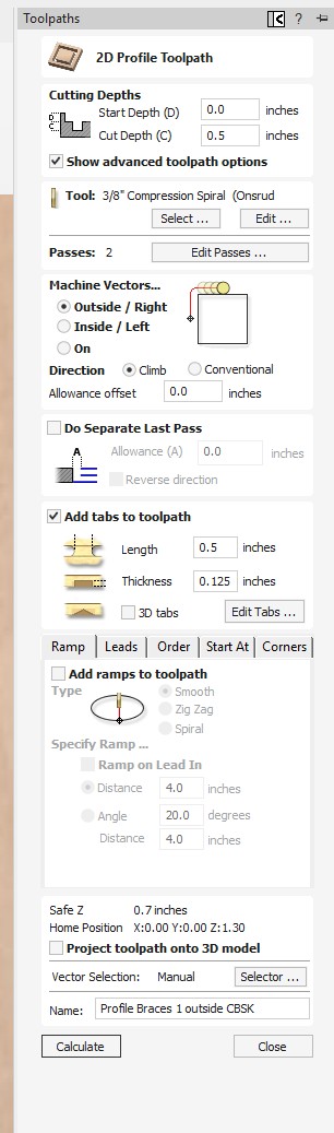
I did profile cuts for most everything, but did pocket cuts for my brace females and my slot. You can see the settings in the picture below.

My slot is a bit wide for my sheet metal roof, but I wanted to leave room in case I was able to get a piece of plexi eventually. I am hoping my braces will have a snug enough fit that I wont need glue, but we will see.
Found this site later about dogbones. Wondering if I should have used the traditional dogbone to have more area for my brace fit contact.

The tool path for my entire cut out was made up of 6 tool paths. I could have done it in 4, but liked the idea of checking after different cuts.

CNC Shop Bot @ CLS
I measured the wood. The caliper only went out two digits and the wood shop measuring tools didnt go small enough. I measured .45 inches thickness. Unfortunately, my parametrics are in fusion, not Aspire. Mr. Dubick said we will be able to use an offset to make up for the slot and brace areas.

We lined it up to one side of the front corner of the machine spoilbaord.
To Fixture my material to the Machine we used the nail gun. When we are using the shopbot CNC, we are using the plastic nail gun. They are strong vertically, but very weak horizontally. Easy removal, we just tap the side of the wood when we are finished and the pins sheer.

Dorian helped me get my wood onto the table. It's too big for me to lift by myself. Then we nailed the wood down to the bed. We nailed all around the outside about every 10 inches or so. Later, we started nailing in the center when we noticed that the wood had bowed up in the middle and the bit was scraping across it leaveing a line.

I loaded my file into Aspire on the shop bot machine and then we checked for any changes to the set up that might not have transfered. The material was still being measured from the bed ad the dimensions looked good.
We must wear the faceshields when we are using the CNC machine. Ear protection is a plus. Hair tied up
When we loaded up my file and started looking at how it would cut closer up, we saw that it would be taking a good amount of material off of my ends, leaving just a stub. So we had to switch to a smaller bit with more passes. This will take more time.


Jog - when you want to move the gantry X is long side of machine Y is skinny side near desktop JX, 48 = jog x to 48 From the origin, but only moving X - leaving Y where is was 0.0 is the corner towards the big TV on the wall. From 0,0 point (not from where you are on the machine at that moment)
The big TV allows the teachers to see what is going on from anywhere in the lab.

To pause - hit the space bar
We will make our origin where we want it when we are making our pieces. In our original practice work, We weren’t making an offset, we were changing the origin. We could make an offset. Later, I did end up making offsets for my pieces to make them tighter
When you do your aircut - the bit needs to be spinning. In case your aircut isn't high enough, make sure the bit is spinning so that if it runs into material, it will cut through it instead of breaking. The bits are expensive - $90 plus each.
- Router on (bit spinning) = green button.
- Listen for whining as bit starts spinning
Helpful commands - ZZ - zero the Z axis - ZX - zero the X axis - ZY - zero the Y axis
Do a ZZ when you are at Z = 4 so that you can run the air pass.
Note: 70 y 0 z 0 = is the Z plate zero-ing spot
Before Running our Air Cut, Make sure that compressed air is on…
Open vents in shop bot,

(CLAUDE PROMPT - make me a collage of these three pictures to put in my documentations)
BIG MACHINE = HIGH STRESS - late night.. took 4+ hours to do my cuts, and I almost broke the machine because I wasn't pressing the keys down hard enough. I somehow zero'd the machine in the wrong place which cuased it to dive when I tried to jog it. Fortunately, Mr. Dubick was able to reset the machine in about 15 minutes and we started again. I learned to use the mouse and click harder. My cut ended at 10:45pm. I am a morning person, this was way past my best functioning hours.
I had a good amount of anxiety around the fact that there are not many training wheels on this very large industrial machine. If you tell the machine the wrong place, there isn't a global/ instructor inputted zero that says.. "no no, are you sure you want to go there?" The machine is expensive and so are the bits. Also with so many students to get through the cutter this week, if I were to break it, then all the other students would suffer. Going first exacerbated this fear.
C3 - resets to zero in front corner

Then measure to where you want manual zero - which is where you want to start your cut using the jog commands
Then load file Enter - this runs the air cut
IF Air cut looks good, Run our cut path C3 - zero machine JZ,4 - move to Z - be over material and your posistion for your program
All ppe on, others behind yellow line
Load file, enter
Start Router (as reminded by the program)
Start fan, vacuum
Then hit - Ok - program will start running
Hand by space bar - the space bar lets us pause the machine if we think something isn't going correctly. The curser stays over the stop at all times so you can stop it quckly if need be. There is also a big red stop button.
We ran a test on the square intake area. We cut one brace piece to try in the test spot.

The fit was loose so we decided that we wanted to add an offset to make it tighter.

My fusion model is parametric, but it would have taken a good amount of time to go there, change things, export, and then redo the dog bones.

We have a cheat sheet on offests that we used to figure out that we wanted to add to the offset.
We decided to a few different offset runs to see which offset would be the best for my fit with my brace pieces.

We cut .01, .015 and .005 offset.

The smallest worked the best, so we set that offset for all our square spots and ran that cut first. After that cut, we decided to run all the cuts that had the small squares first and confirm it worked.

After that cut well, we started running the other pieces

I made pocket cuts for both the little squares and my long roof parts. The pockets on the roof parts cut all the way throug in parts becuase the cut was dep and the the
When finished, move the gantry out of way J2 16,68 (depends on how big your file is) Zip tabs out with tool. I zipped all the tabs on both sides.. Then used sandpaper to finish the edges a bit.

After we finished, we removed the cut pieces and then we scraped the bed to get any pieces of the plastic nails that are left over.

Clean up with vacuum
Then I started sanding... all the inside parts and outside edges. On outside edges, we were able to use a hand held sanding machine, but inside parts were hand sand with the paper. We used the belt sander to sand the pieces that were cut out for the art department since they were fun shapes.

I used a paper to draw an image and gave it to the HVAC shop that I work at to cut out a square pieces of sheet metal for the roof. We crimped the edges so they would be a bit thicker (and less sharp for handling). My original design is for plexi glass to have a clear top, so we'll see how those thicknesses work out. The sheet metal is thinner than .25 plexi that I designed for. I requested that they the trimble plasma machine at work to cut out the square with tabs, then crimp the edges either with our machine that does edges, or the break.

I am not heavy enough or strong enough to use our break at the shop.. I just hang from it when I try to pull it down.Since I needed a roof and we didn't have plexi/ acrylic/polycarb that was the right size.. its pretty expensive, I thought this was a good second choice.


Some pieces cut all the way through and sometimes it just did a pocket like I programmed.

This variation was becuase of the bow of the wood. This didn't really hurt my assembly as the braces did fit in the slots. You can also see where that bowing of the wood caused the bit to drag along my board and leave lines. This is all on the inside walls of an outdoor shelter so it doesn't impact the overall asthetic terribly- but if it was a museum piece, I would need to really nail it down or pick better work.

In the top slot where it cut through almost all the way on one side, I plan to cut it out all the way so I can chose different materials for the roof.

I started with assembling on one side and then using a garbage can to hold the roof in the slot, this was kinda working.. but the braces were wiggling.. and falling.

Super grateful to my classmates Dorian and Maxwell for helping me assemble the rain shield.

All good that it assembled, but to make it stout, I will probably add glue and maybe brads.

Dr. Taylor showed me some tricks for glue. We put wood glue in the holes before we pushed in the braces. Then we dripped a bit of super glue on them and some accelerant. Then we secured it with a picture frame holder strap and left it over night to harden.
Next day, it was pretty secure. I wanted to make it more robust so Dr. Taylor gave me a great lesson on the Brad gun.
I put two brads in every brace to make the structure more robust. I cut out the rest of the slot with the tab cutting tool on one side where the board had bowed adn it had mostly cut through the wood to make it easier to slide in my sheet metal roof or change that material later. Used a shim to tighten the fit between the sheet metal and the side plate slot. Then I used the extra brace that we printed to make a tighter fit between my upper braces and the roof and prevent the sag of the sheet metal.
