computer-controlled cutting
Group Assignment
- Do your lab's safety training
- Characterize your lasercutter's focus, power, speed, rate, kerf, joint clearance and types.
- Document your work to the group work page and reflect on your individual page what you learned.
Individual Assignment
- Design, lasercut, and document a parametric construction kit, accounting for the lasercutter kerf.
- Cut something on the vinyl cutter.
Additional Learning
Branching
I made a pretty big mess week one forgetting to pull on my travel lap top before I started editing my site. I asked Kenny Hu to teach me how to branch correctly. I had watched the videos, but still didn't feel confident that I wouldn't break my site. He works in the industry and was able to help me learn best practices, and supervise my first merge attempts. Summary: Work in a branch, don't merge until it's really good and tested.
The below image shows that I have files modified, two saved and ready to commit. I am working in the workingBranch.

Then we worked more on using the command line to push, pull, find out where we are, and confirm our tree is clean.

If I make branch on another computer, I need to publish that branch and push. Then I can use
git fetch origin
so that my other computer can see the published branch from the other computer. Then, on the new computer, I can use
git checkout WorkingBranchWk3
After checking out the branch, I pull just in case.
Then I check it with git status
The Work - Group
Safety Training
Safety is a priority. Don't leave your print. If you are printing, you are there.
Characterize your lasercutter
CLS has 3 laser cutters!!!
Link to our group page here.
I really enjoy my group. We really are excited to help and teach each other. We all want to do what ever we can to be a good group member. Sometimes it gets hard becuase not everyone can do everything at the same time, so figuring out who should do what and when can be a challenge, but I think we worked through it well.
My summary is that in general on our lasers, we need to take kerf into consideration with the wood by about .01mm
It also depends on the application. For making joints, I wanted a tighter fit so I added for kerf. For a pass through slot, I might not add anything and let the kerf be my ease of motion.
For cardboard, the kerf did not to make much difference.
The Work - Individual
Model files available: parametric (STL), laser(DXF and SVG) and silhouette(studio3) here
Parametric Kit
Some of the options discssued were: Blender geometric node. This looked cool but terrifying.
FreeCAD: Since sometimes I work with students who are resource constrained, I decided to try this one . I made a base plate with a couple of paraemtric dimenstions. The CAD file is in week 2's model file.
Onshape is provided to First(R) teams for free, so I decided to try parametrics there and was able to make a model of a votive candle holder. If I were to make it again, I would change the shape of the wall to make it easier to constrain. I struggled to be able to tie in the radius of the model becuase I couldn't constrain the curved surface the way I wanted to. I learned about the global variable which travels throughout the whole model and the local variable which is specific to this part tab.

Part Studio variables show up on the left side.

All variables, you need to click on the box on the right side of the screen to show them or on the table tab at the bottom of the screen. I made many of my variables while I was dimensioning using the # to start my name which let Onshape know I was creating a variable.
I was able to change the hieght and where the upper ring was. I was also able to modify the width of the upper ring, and my material width so I could account for the Kerf we calculated in our group project.


I messed with the wall sketch so much that I ended up learning how to revert to a previous version in Onshape becuase I couldn't find my way back and I had deleted a reference item that my parametric table needed.

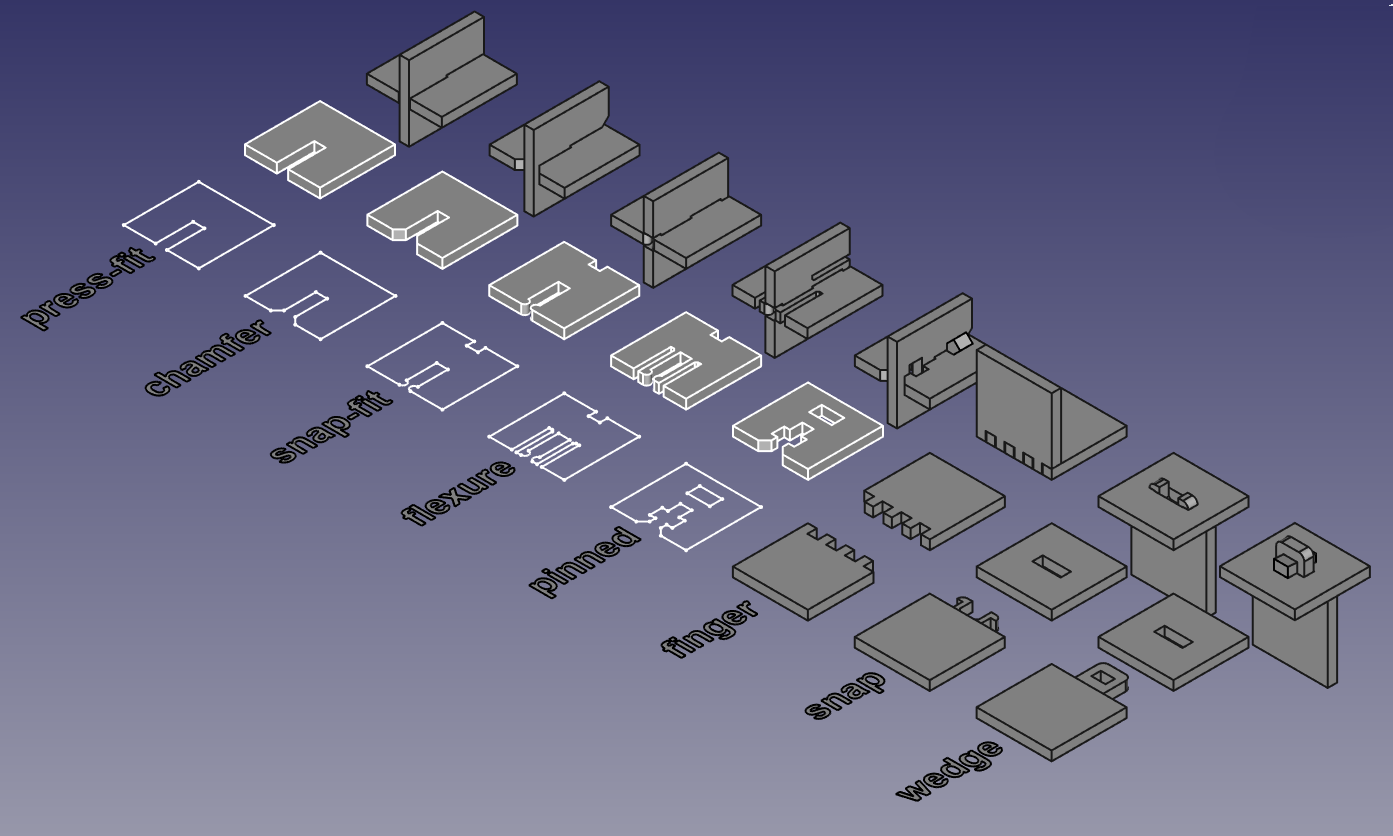
It was still bothering me that I couldn't change the height as much as I wanted to, so I went back at it again the next day. I figured out it had something to do with the corners. Collin Kanofsky suggested that I fillet my corners after I extrude to make it easier to constrain my model. That helped. Then I also changed my model to incorporate different locking mechanisms for a press fit model. In a google search, I found a joint guide on the fab page of Jan's journey
I did some VERY rough sketches of the model and the slots and notches to think through my ideas for the press fit.

I incorporated a chamfer at the top and a nub and lock at the bottom plate.


I modified the constraints and the geometry of my wall piece and then I couldn't select it to extrude. After a bit of google research, I found the profile inspector which showed me where my issue was with a disconnected line and corner.

I changed my variable names to note which one controlled most of the dimensions.

Since I used formula's a few of them were tied together, and I didn't want to modify the wrong one and lose my formula connection.

Printing the Parametric Kit
I think I went about this a bit backwards. Since I didn't know how to start, I started by looking at what kind of file I would need to print the pieces. I remembered that we used corel draw, and I was hoping that whatever file type that was, I would be able to make it in another program that I have and bring it to the lab to print.
From our lab work flow page:
Preparing the File 1. Go to the FabLab Google Drive. 2. Download the CorelDraw file (must be a CDR). 3. In CorelDraw, make sure everything you want to vector is hairline (.01). 4. For parts you want to raster, do not use hairline. 5. Click File→ Print. 6. Do not hit Preferences (for this laser cutter)! 7. Click Print.
This let me know that I need to get my pieces to cut into a vector file. Aha... now to figure out if I can make that in Onshape or need to bring it to inkscape.
I exported the file as a dxf and then imported it into Inkscape to work with it. I would need 18 copies, a base and an upper rim.
When I first did an import, I forgot to change the dimensions on the workspace and it came in tiny. After changing the dimensions, it came in fine, but I it was missing the upper cut out becuase I exported the sketch that I made the wall with, not the wall outline after the upper ring is subtracted.


I made another sketch at the intersection of the current wall and then exported that as DXF, and then opened in Inkscape to make my vector file for cutting. For my other parts, I used planes and the use function to make projections that I exported as DXF files. When I made my projections using the use funtion, I didn't need to add the variable names as dimensions. When I tried to do that it overconstrained the model. The dimension was already tied to the variable through the use function.

In inkscape, I lined up the pieces and made 16 copies of the rim walls. Then I changed the stroke to .01 and they all dissapeared. However, with a bit of searching I found view > displaymode > enhance thin lines. Then you could see them again. I changed them red for cutting.

Then I was able to print my kit on the Epilog Fusion M2S with the stored settings that came from Epilog that we use in the lab.

There are separate settings for Engraving as well. We used the 300 dpi unless we are doing something really fine and special.

Then I chose the settings for Cardboard.

...and for engraving

It ended up that I had only printed 12 legs when I needed 16. This worked out well in the end becuase, as noted below, I needed to change my notch/locking system before printing in wood and this game me the opportunity.
Running the laser a few extra times was great for my confidence with the machine. When I cut the base out, I added engraving my initials in black before I printed. Anything that wasnt hairline, was engraved.

Accounting for Kerf
For the cardboard model, I didn't really need to account for Kerf, but I did find that my bottom rectanglur notch was way too big! All the bottom pieces were bending and twisting when cut out of cardboard.

So I changed it to a smaller triangle notch. That worked much better. It even clicked when it locked in when printed in wood. You can see that most of them were a bit damaged, but the four with the triangle notch design were better.

Is it a votive holder or is it a vase? It holds awesome classmate Dorian Friztes vynal flowers perfectly. Maybe a vase.... fire and wood, good? Maybe for a bonfire.

For wood we have different settings from epilog
Also different settings for engraving with the wood
Epilog settings wood engraving
For the wood model, I changed my material thickness to .125+ .025 which is full kerf. However, I added it to both sides and it was too small and ended up breaking the wood.

I started with accounting for full kerf, but this left too much wiggle room for a slot. I changed my material thickness to .125 + .0125 which is half of the kerf. Our Kerf mearusing tool indicated that we would want to be around.02 inches smaller to have a good fit. In reality, the best fit was .0125.

In summary, I was using a solid cut out for material thickness variable that made the solid cutout for the notch at the top. So as noted above, I did end up printing it once too big (I added material in my extraction instead of subtracted - making my slot too large). Then I subtracted the material to from my cut out for my slot, which made it too tight. Then I halved the kerf modification and that was a good fit. This was relatively easy to do becuase I had designed my model to have a material thickness variable.

Vinyl Cutter
I started with a picture of a plush toy. It had so many gradients of green that it made it difficult to use the traditional trace methods to outline it.
I tried making something similar in Gemini Banana. I didn't love it.. looked like a coconut drink from a Hawaiin location. Although it was a good to experience Gemini Banana, the image still had spots that I thought wouldn't work well with inkscape.

When I found out that we had machines that worked with silhouette in the lab, I started working in silhoutte.
I had found a resourse at Silhouette Tutorial. However, most of my help came from my amazing classmate Angela Horstman.
First she showed me how to trace and I started playing with the all the settings until I was able to get a good trace to start working with.

Once I traced the image then I learned to compound the path so that it would create the nodes that I could then edit.

She showed me how to edit nodes, make copies and fill them in with colors to make it into color to model what the sticker would look like.

I liked editing the nodes so much that I started drawing and editing to remake the image since it didn't trace well becuase of the gradations of color. I liked it becuase it reminded me of a southpark style drawing. This node editing is like a simplified version of what I learned in inkscape.
After I had all the pieces ready. I moved them into corners of the page, then matched vinyl pieces to those areas.

Following the lab protocal and the 7th grader assigned to lead me through the process in our lab, we printed the pieces.

We used the preset settings that came from silhouette when ee chose the material.

I used glossy vinyl in my pieces.

Next comes weeding(taking out the pieces of vinyl that you don't want with a long pointy dental utensil), then using the transfer tape to line up the pieces.

The piece were jumping up to the transfer tape, so taping them to the table was the way to go.

Unfortunately, when i was lining up the white piece, it was hard to see and I put the piece in upside down. I was able to pull it out, but it had to be reprinted.

I got googly eyes! I used small pieces of really strong double sided tape that we use in the lab on the CNC machines when securing boards to the table of the machine. All assembled, coco went up on the window.
