Week 9:Input Devices
Assignments
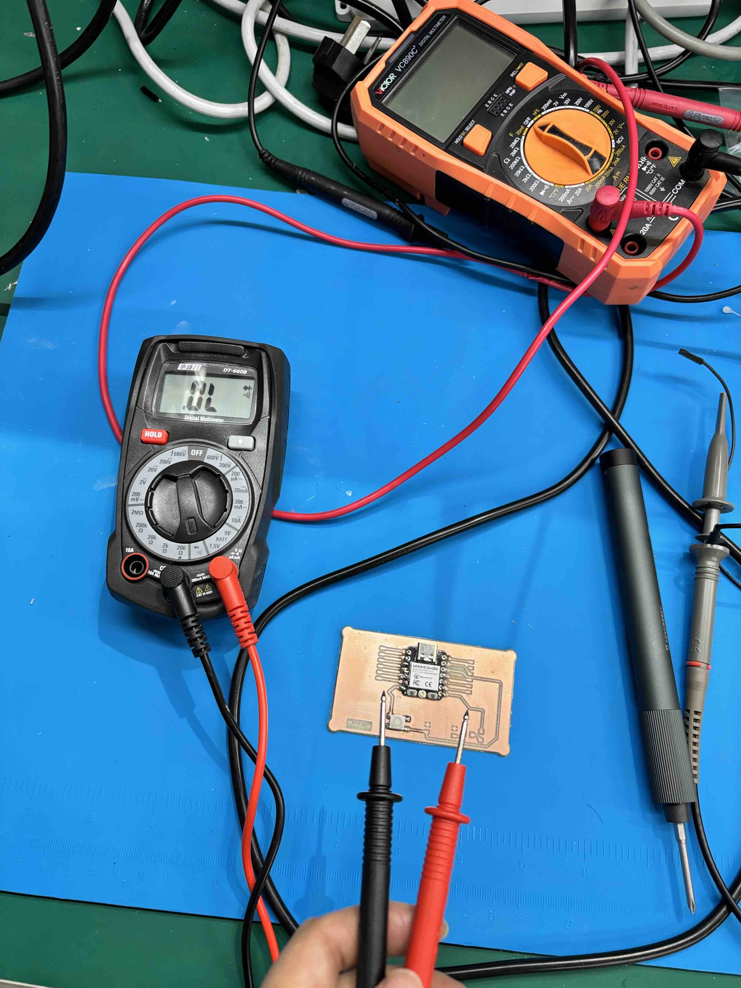
Group assignment: Probe an input device’s analog levels and digital signals. As a minimum, demonstrate the use of a multimeter and an oscilloscope. Document the work on the group work page and reflect on your individual page what you learned.
Individual assignment: Measure something — add a sensor to a microcontroller board that you have designed and read it.
Group Work Assignment Reflection
In the group assignment, we compared how a multimeter and an oscilloscope show the same input devices differently — steady values vs. signal shape over time.
Summary Table: Multimeter vs. Oscilloscope
| Feature | Multimeter | Oscilloscope |
|---|---|---|
| Potentiometer | Shows exact steady voltage (e.g., 2.34V). | Shows smooth, continuous voltage ramp over time. |
| Push Button | Shows 0V or 5V (static, ideal state). | Shows switch bounce (multiple voltage spikes) during the first ~5ms of contact. |
| Best for… | Measuring absolute resistance, average voltage, continuity. | Visualizing signal shape, timing, glitches, and transitions. |
What I learned: Use a multimeter to verify the DC operating point of a sensor (e.g., “Is my potentiometer outputting 1.5 V?”). Use an oscilloscope to verify the integrity and timing of a digital signal (e.g., “Does my button bounce? Is my serial data line clean?”).
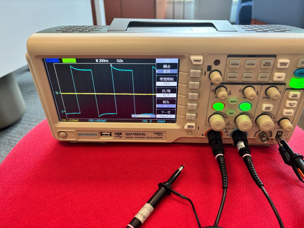
Using the oscilloscope — OWON EDS102CV setup
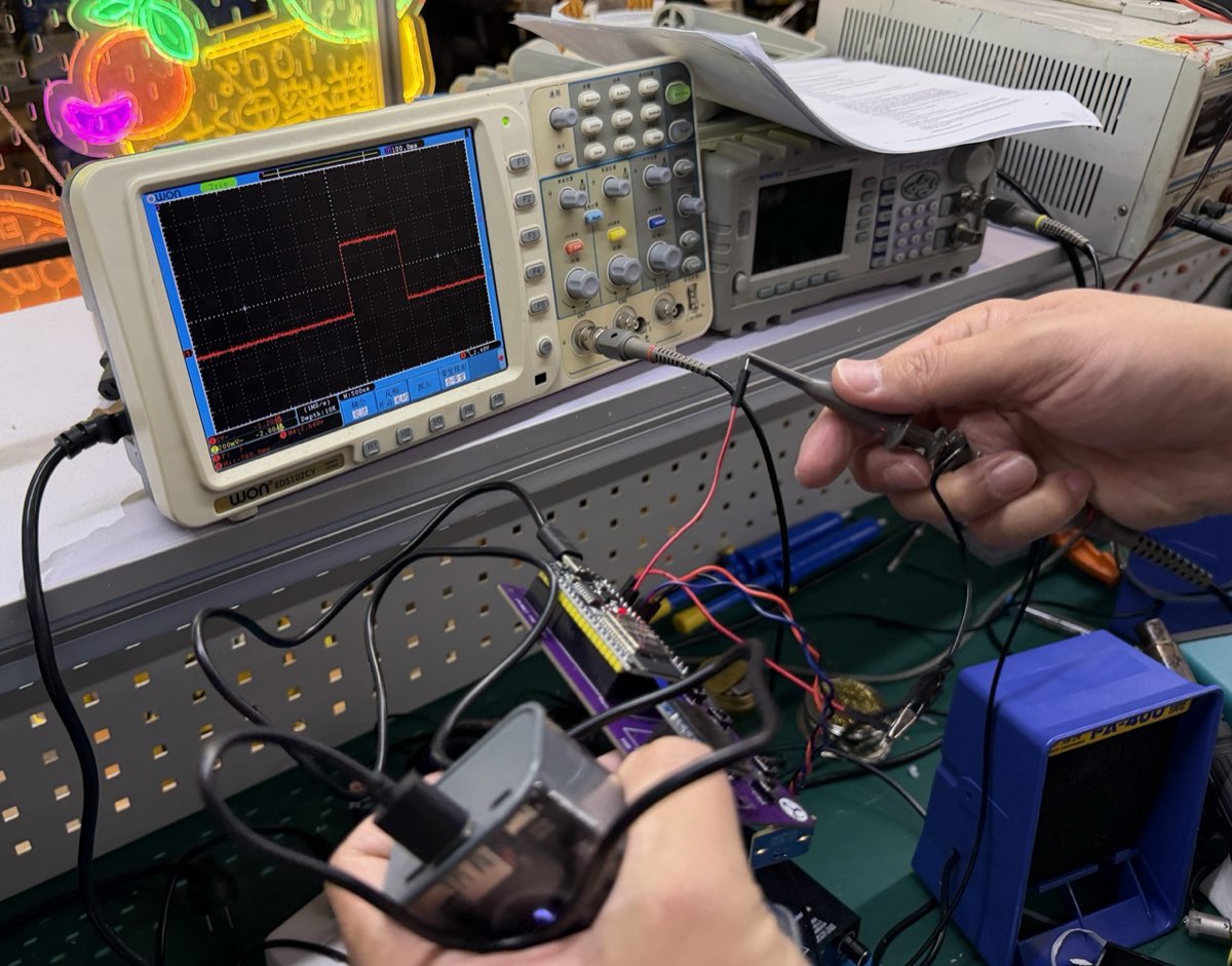
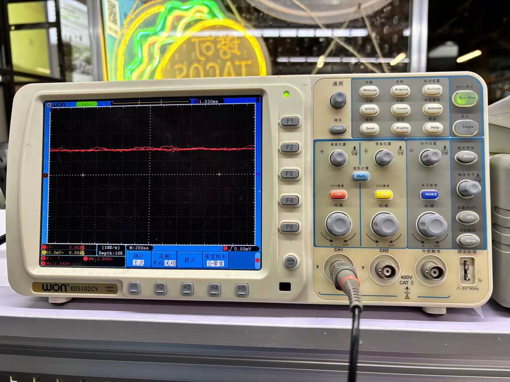
In the lab we used an OWON EDS102CV (100 MHz bandwidth, 1 GS/s sample rate) digital storage oscilloscope to probe signals on breadboard circuits and populated PCBs. Before measuring a real input, we walked through the main parts of the front panel and how they map to what appears on screen.
How to set up the OWON EDS102CV
- Power on — Connect the mains cable, press the power button, and wait for the boot screen to finish.
- Connect the probe to CH1 — Plug the BNC end into the CH1 input. Set the probe switch to ×10 (10:1) unless you need to measure very small signals.
- Ground the probe — Clip the black ground lead to a GND point on the circuit under test (same ground as the scope and the board). Never leave the ground clip floating.
- Touch the probe tip — Place the tip on the signal pin you want to observe (e.g. potentiometer wiper, button output, or serial line).
- Select the channel — Press the CH1 button so the channel menu is active (highlighted in red on screen).
- Quick start with Autoset — Press Autoset (自动设置) once; the scope scales volts/div and sec/div automatically so the waveform fills the grid. Use this for a first look, then fine-tune manually.
- Vertical scale (Volts/div) — Turn the 伏/格 knob for CH1 to set voltage per division. For a 0–5 V logic or pot signal, start around 1 V/div or 2 V/div.
- Horizontal scale (Sec/div) — Turn the Sec/div knob to zoom in or out in time. Use a slow timebase (e.g. 10 ms/div) to see button bounce; use a faster timebase (e.g. 200 ns/div) for high-frequency pulses.
- Coupling — Press the bottom menu keys (H1–H5) and set 耦合 (Coupling) to DC (直流) for absolute voltage levels, or AC to ignore DC offset and see small AC ripple.
- Trigger — Set trigger source to CH1, mode to Edge, and adjust the trigger level knob until the waveform is stable and the Trig indicator stays lit (not free-running).
- Run / Stop — Leave in Run for live signals; press Stop to freeze the trace for measurement. Use Single to capture one event (useful for a single button press).
- Probe compensation (first use) — Connect the probe tip and ground to the Probe Comp terminal (5 V 1 kHz square wave), press Autoset, and adjust the small screw on the probe until the square tops are flat, not rounded or overshot.
Front panel map (what we used in the group test)
- Vertical (CH1 / CH2): channel select, vertical position, Volts/div — moves and scales the waveform up/down.
- Horizontal: HORIZ button, horizontal position, Sec/div — moves and scales the waveform left/right in time.
- Trigger: trigger menu, level knob, 50% button — locks the display to a repeating signal.
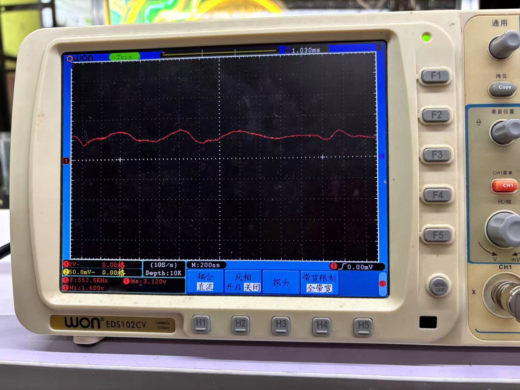
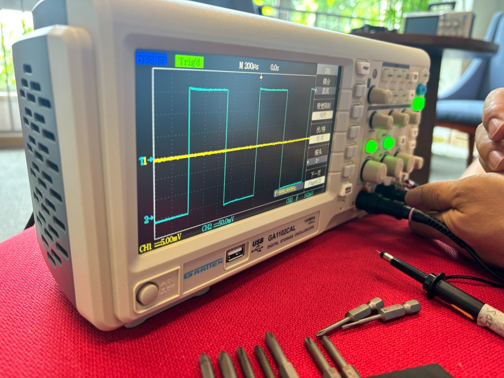
- Measure / Cursor: read frequency, Vmax, Vmin on screen (e.g. our push-button test showed bounce spikes in the first few milliseconds).
NOTE: Connect CH1 and CH2 for calibration before use.
Probe BNC 接头 → CH1
Probe Ground Clip(鳄鱼夹)→ Calibration GND
Probe Tip(探针尖)→ Calibration Output(Probe Comp)
Channel:CH1
Probe:10×(如果你的探头拨到 10×)
Vertical Scale:500 mV/div 或 1 V/div
Time Base:200 μs/div 或 500 μs/div
Trigger:Edge
Trigger Source:CH1
Trigger Mode:Auto
Trigger Level:约 1 V
Oscilloscope

    CH1
     │
     │
  Probe
     │
  ┌──┴──┐
  │     │
 Tip ─┘     └── Ground Clip

Tip  ─────────> Probe Comp (~1 kHz square wave)

Ground Clip ──> GND
Individual Assignments
Sensor & Microcontroller Introduction
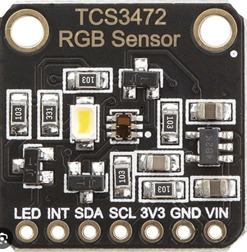
TCS3472 — The RGB Color Sensor
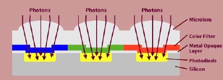
What Is An RGB Sensor?
RGB stands for Red, Green, and Blue. An RGB sensor can independently detect the color intensity of red, green, and blue colors. It can also measure brightness. The color sensor achieves this by using an RGB color filter at its input. The red color filter allows only the red color to pass through it. The light falls on the photodiode, whose current will vary depending on the amount of incident light. The current will be converted to a voltage using a signal conditioner which can be read using an ADC.
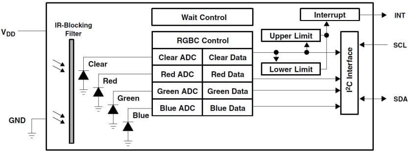
Block Diagram
Here is the block diagram of the TCS34725 sensor. The IR block filter in the TCS34725 helps in sensing ambient light. Ambient light sensing is used in your phones when you set the brightness level to Auto. You can also find applications in TCs and Screens whose brightness will adapt automatically to their ambient. The TCS34725 has an I2C interface (SDA and SCL) that connects to the Arduino Board. The IC also has an optional interrupt output pin which can be used to interrupt Arduino. An example application is a fruit sorting machine. The color will be different if a fruit is not ripened. The Arduino can use this interrupt to trigger a solenoid to let the unripened fruit into another conveyor.
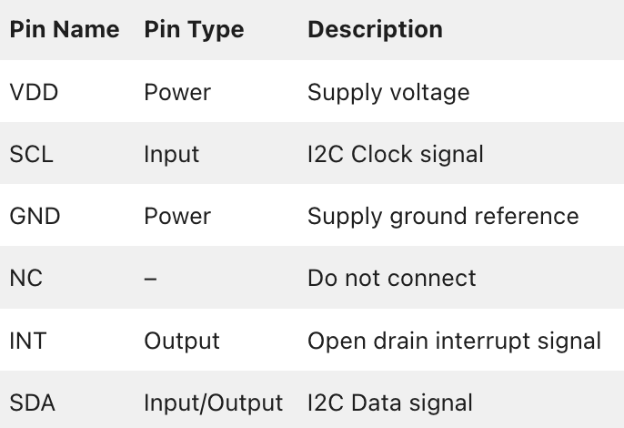
Pinout of TCS34725
The below table gives the pin description of the color sensor IC – TCS34725.
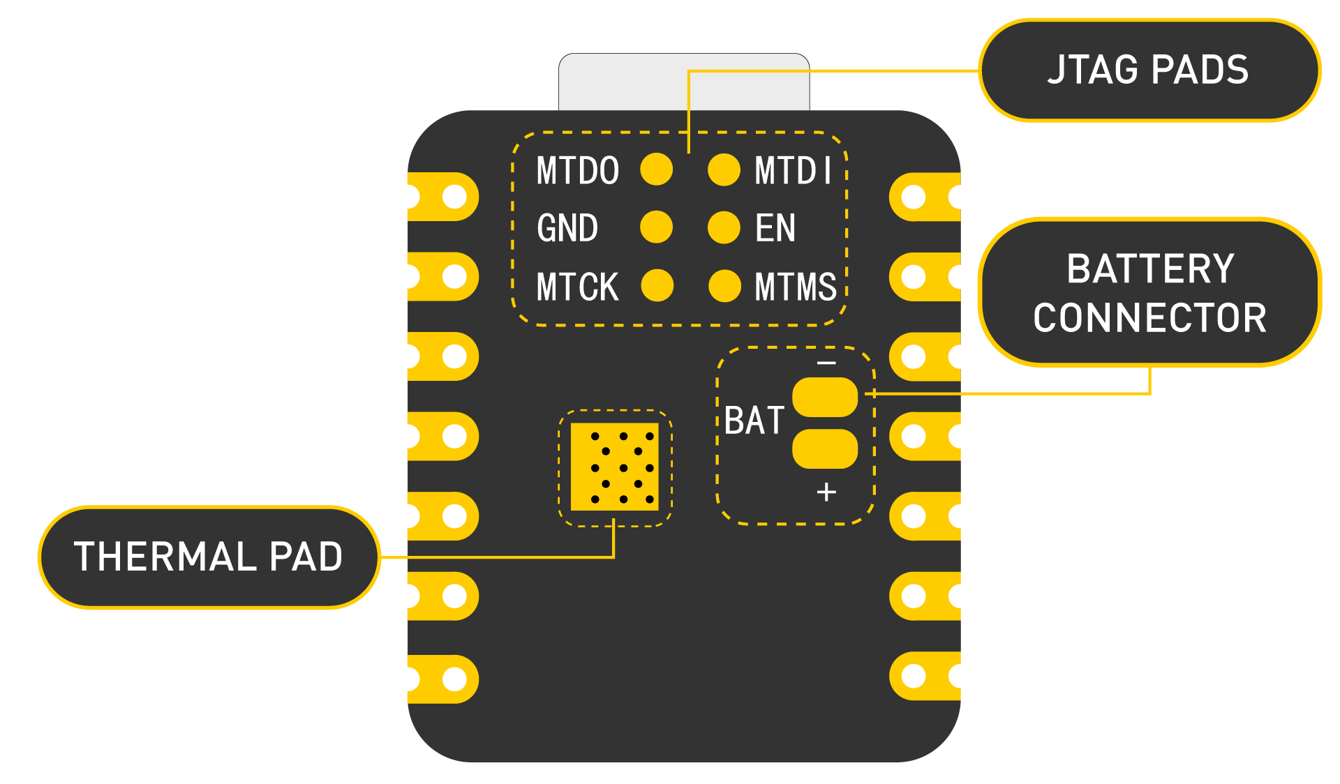
XIAO ESP32-C3 — The Microcontroller
The XIAO ESP32-C3 is an ultra‑compact development board built around the Espressif ESP32‑C3 chip (RISC‑V, 160 MHz). It features 11 digital I/O pins, 4 analog inputs, and supports I²C, SPI, UART, I²S, Wi‑Fi, and Bluetoot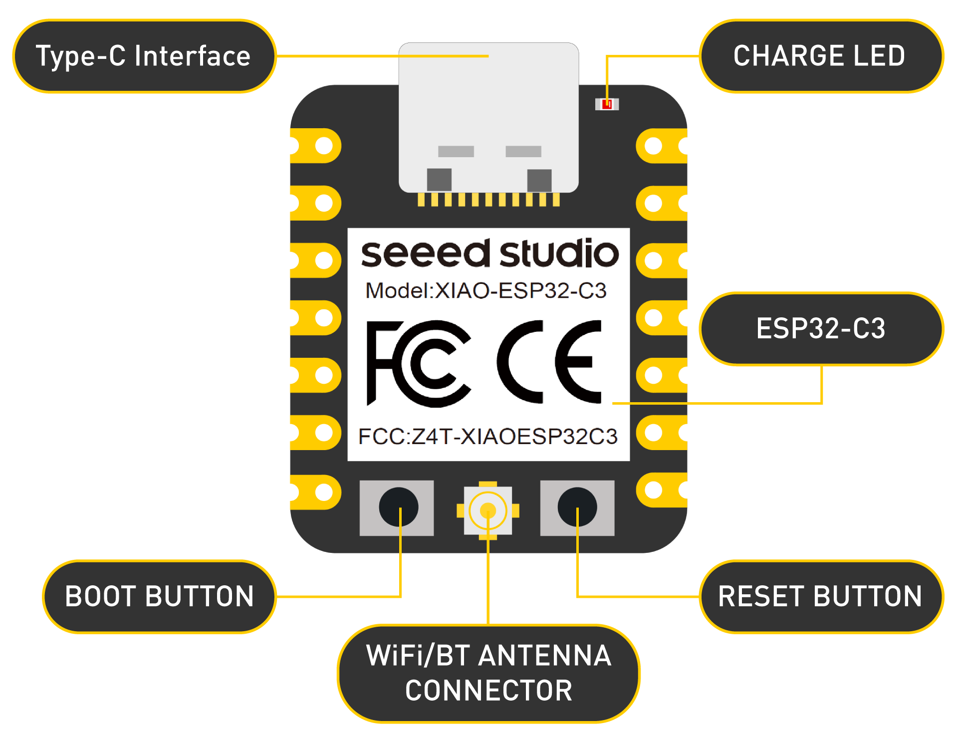
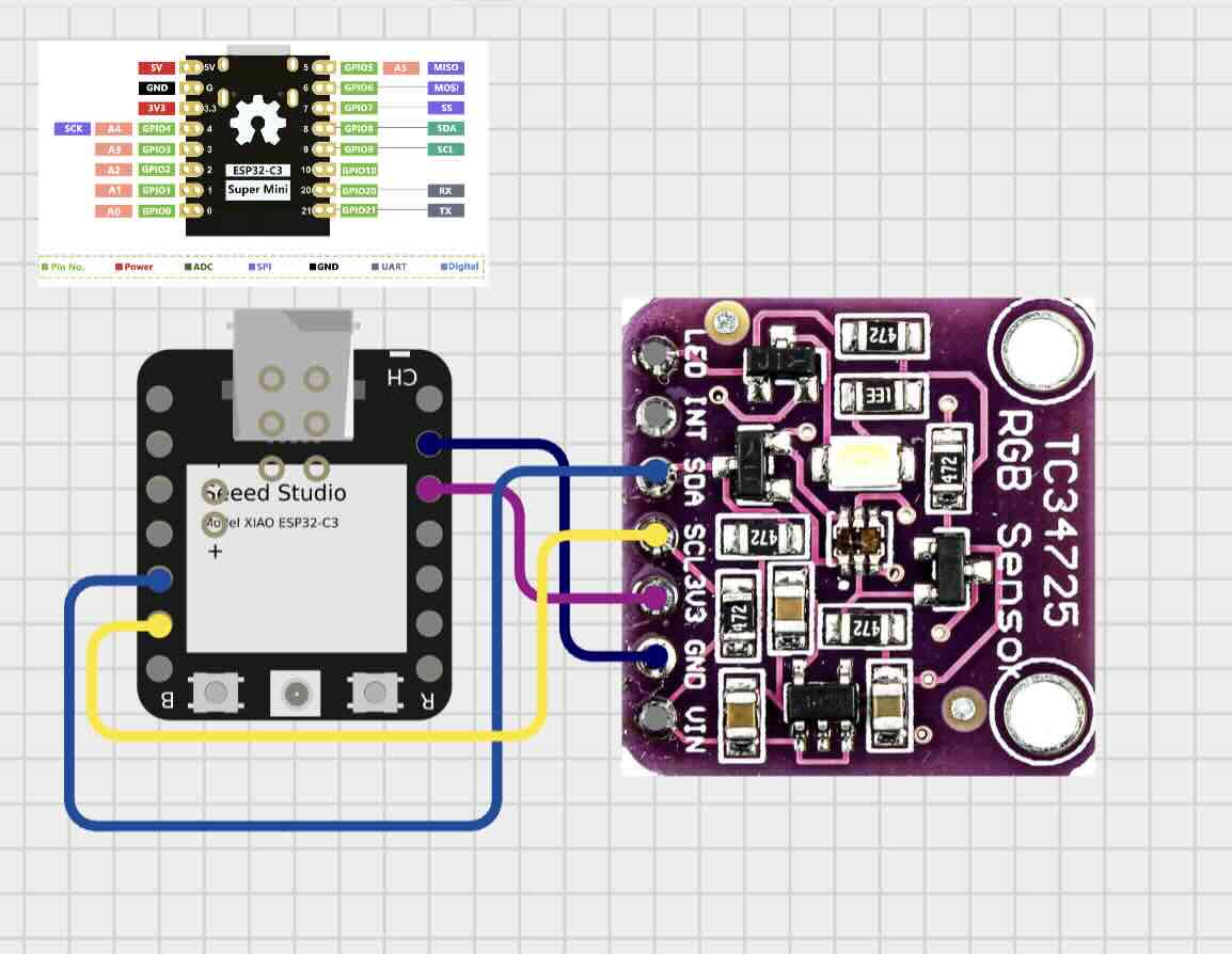
Circuit Design & Wiring
| TCS3472 Pin | XIAO ESP32-C3 Pin | Function |
|---|---|---|
| VCC (3.3V–5V) | 3V3 | Power supply |
| GND | GND | Common ground |
| SDA | D4 (GPIO6) | I²C Serial Data |
| SCL | D5 (GPIO7) | I²C Clock signal |
Wiring diagram (ASCII):
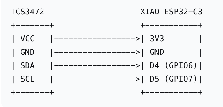
Note: The XIAO ESP32-C3 runs at 3.3V logic. The TCS3472 module accepts both 3.3V and 5V, so direct connection is safe. If using a bare TCS3472 chip, ensure VCC is 3.3V only.
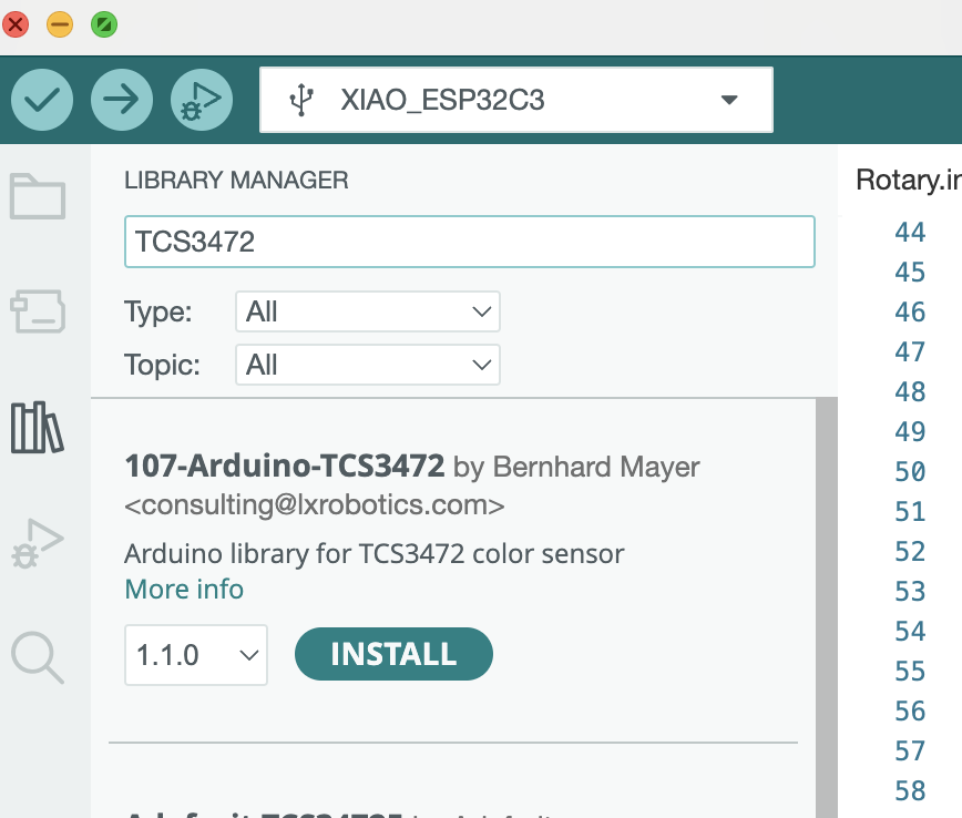
Code Implementation
Adafruit_TCS34725 — Install via Arduino Library Manager (search “Adafruit TCS34725”)
Complete Arduino Sketch
/*
Fab Academy 2026 – Individual Assignment: Input Devices
Board: XIAO ESP32-C3
Sensor: TCS3472 RGB Color Sensor
Date: May 15, 2026
*/
#include <Wire.h>
#include "Adafruit_TCS34725.h"
// Create TCS34725 object with default I2C address 0x29
// Parameter values: Integration time (2.4ms) and gain (1x)
Adafruit_TCS34725 tcs = Adafruit_TCS34725(TCS34725_INTEGRATIONTIME_2_4MS,
TCS34725_GAIN_1X);
void setup() {
Serial.begin(115200);
Serial.println("\n\n=== TCS3472 Color Sensor Test on XIAO ESP32-C3 ===");
// Initialize I2C with specific pins on XIAO ESP32-C3
// GPIO6 = SDA, GPIO7 = SCL
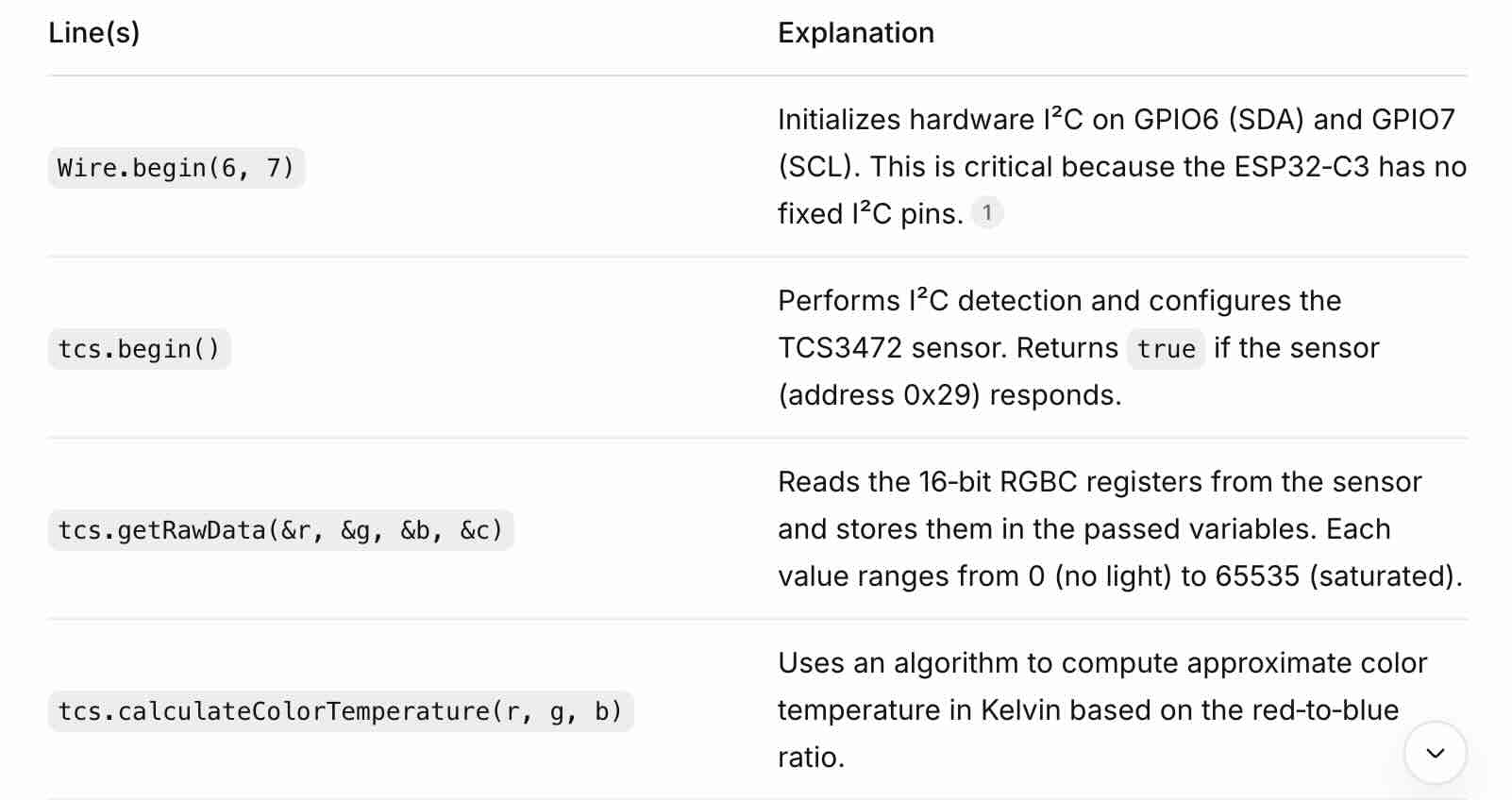
Wire.begin(6, 7); // SDA, SCL
// Check if sensor is connected
if (!tcs.begin()) {
Serial.println("ERROR: TCS3472 sensor not found!");
Serial.println("Check wiring: VCC -> 3.3V, GND -> GND, SDA -> GPIO6, SCL -> GPIO7");
while (1) delay(1000);
}
Serial.println("TCS3472 sensor detected successfully!");
// Optional: increase gain for low-light conditions
// tcs.setGain(TCS34725_GAIN_16X);
// tcs.setIntegrationTime(TCS34725_INTEGRATIONTIME_50MS);
}
void loop() {
uint16_t r, g, b, c; // 16-bit raw values (0-65535)
// Get raw sensor data
tcs.getRawData(&r, &g, &b, &c);
// Calculate color temperature and lux (optional)
uint16_t colorTemp = tcs.calculateColorTemperature(r, g, b);
uint32_t lux = tcs.calculateLux(r, g, b);
// Print to Serial Monitor
Serial.println("========== SENSOR READINGS ==========");
Serial.print("Red (R): "); Serial.print(r); Serial.print("\t");
Serial.print("Green (G): "); Serial.print(g); Serial.print("\t");
Serial.print("Blue (B): "); Serial.print(b); Serial.print("\t");
Serial.print("Clear (C): "); Serial.println(c);
Serial.print("Color Temperature: "); Serial.print(colorTemp); Serial.println(" K");
Serial.print("Lux (Illuminance): "); Serial.print(lux); Serial.println(" lx");
Serial.println();
delay(1000); // Update once per second
}Code Walkthrough
Problems Encountered & Solutions
Problem 1: Sensor not responding
The Serial Monitor showed No I2C devices Not Found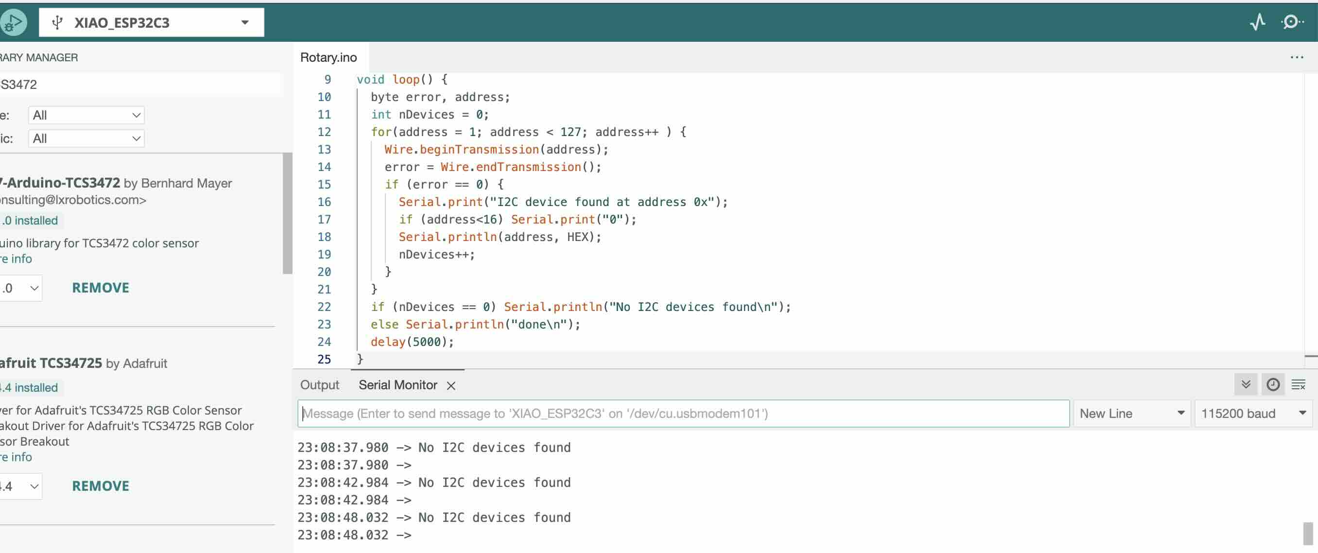
Solution: Check I²C connections and verify sensor is properly powered (3.3V).
Problem 2: Inaccurate color readings under indoor lighting
Symptom: The RGB values did not change significantly when different colored objects were placed in front of the sensor.
Cause: The default integration time (2.4 ms) and gain (1×) were too low, and there was insufficient ambient light.
Solution: Increased the gain to 16× and integration time to 50 ms by uncommenting the two lines in
Gallery
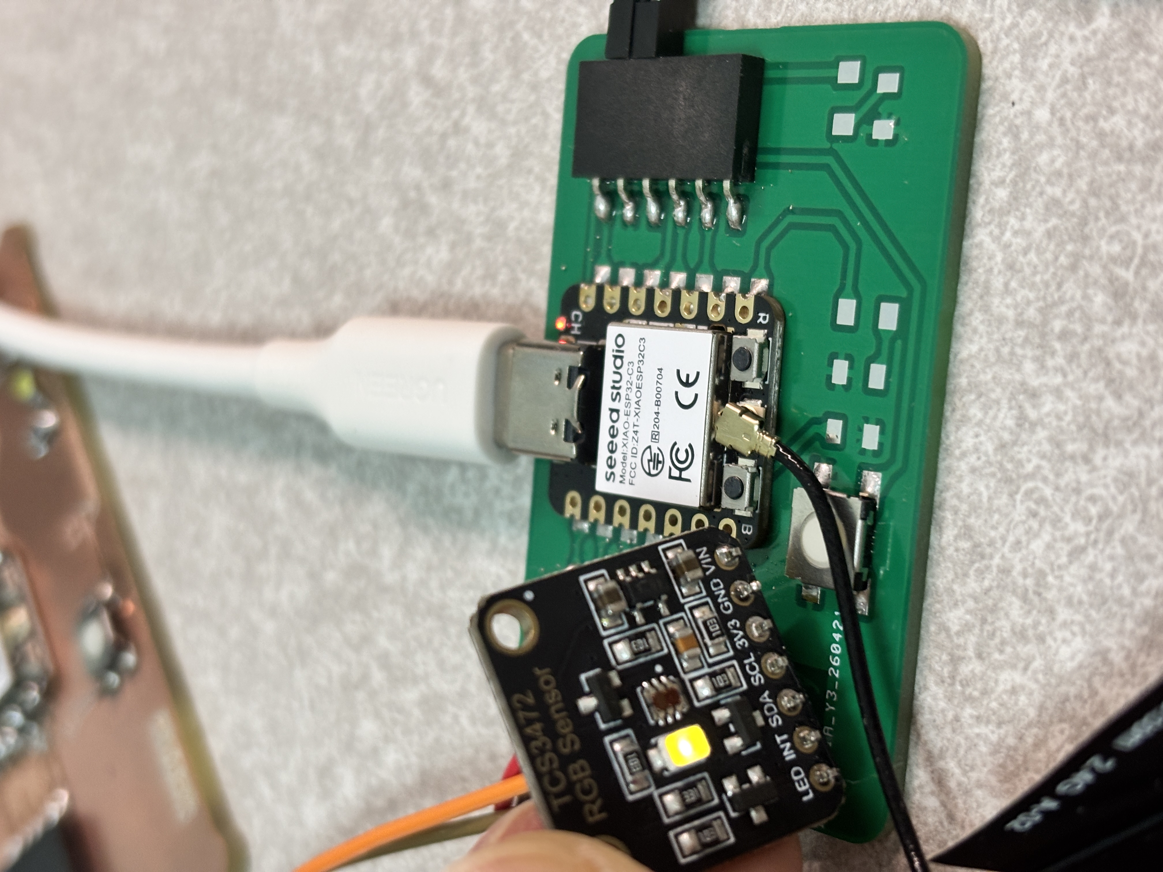
Add a TCS34725 color sensor to my custom ESP32 board and measure I2C SDA and SCL signals.
ESP32-C3 Board — TCS34725 wiring
    3.3V  ---------------- VIN

    GND   ---------------- GND

    GPIO SDA ------------ SDA

    GPIO SCL ------------ SCL
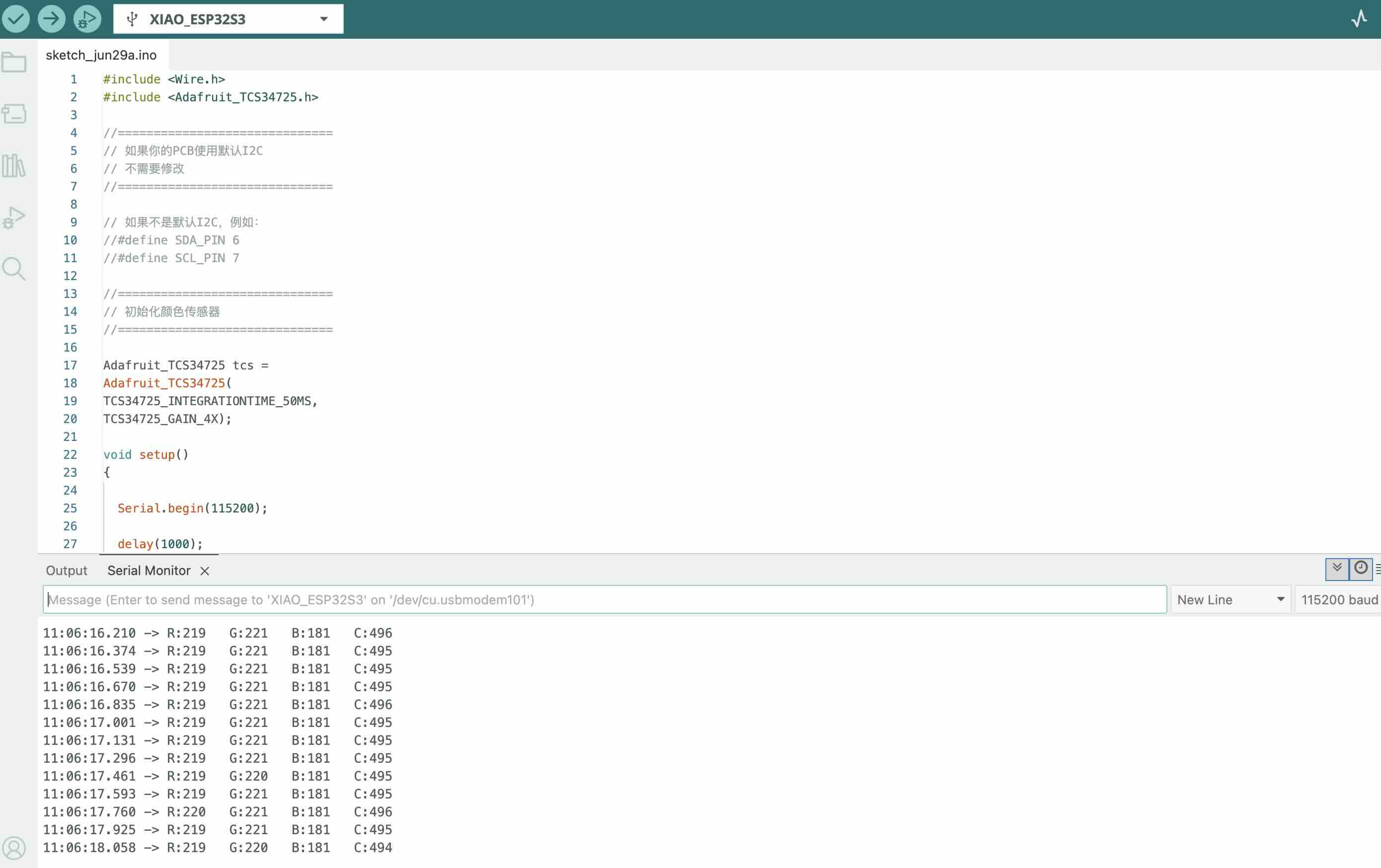
Uplode code to the ESP32-C3 board
#include
#include
//==============================
// 如果你的PCB使用默认I2C
// 不需要修改
//==============================
// 如果不是默认I2C,例如:
//#define SDA_PIN 6
//#define SCL_PIN 7
//==============================
// 初始化颜色传感器
//==============================
Adafruit_TCS34725 tcs =
Adafruit_TCS34725(
TCS34725_INTEGRATIONTIME_50MS,
TCS34725_GAIN_4X);
void setup()
{
Serial.begin(115200);
delay(1000);
// 如果使用自己指定GPIO,请取消下面两行注释
//Wire.begin(SDA_PIN, SCL_PIN);
Wire.begin();
if (!tcs.begin())
{
Serial.println("--------------------------------");
Serial.println("TCS34725 NOT FOUND");
Serial.println("--------------------------------");
while (1);
}
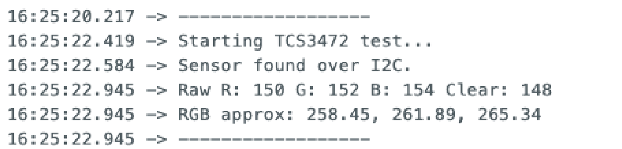
Serial.println("--------------------------------");
Serial.println("TCS34725 READY");
Serial.println("--------------------------------");
}
void loop()
{
uint16_t r, g, b, c;
//==============================
// 读取颜色数据
//==============================
tcs.getRawData(&r, &g, &b, &c);
//==============================
// 输出数据
//==============================
Serial.print("R:");
Serial.print(r);
Serial.print(" G:");
Serial.print(g);
Serial.print(" B:");
Serial.print(b);
Serial.print(" C:");
Serial.println(c);
delay(100);
}
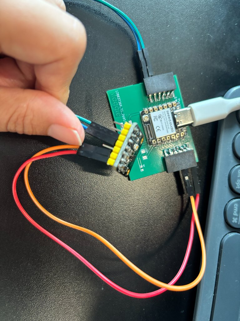
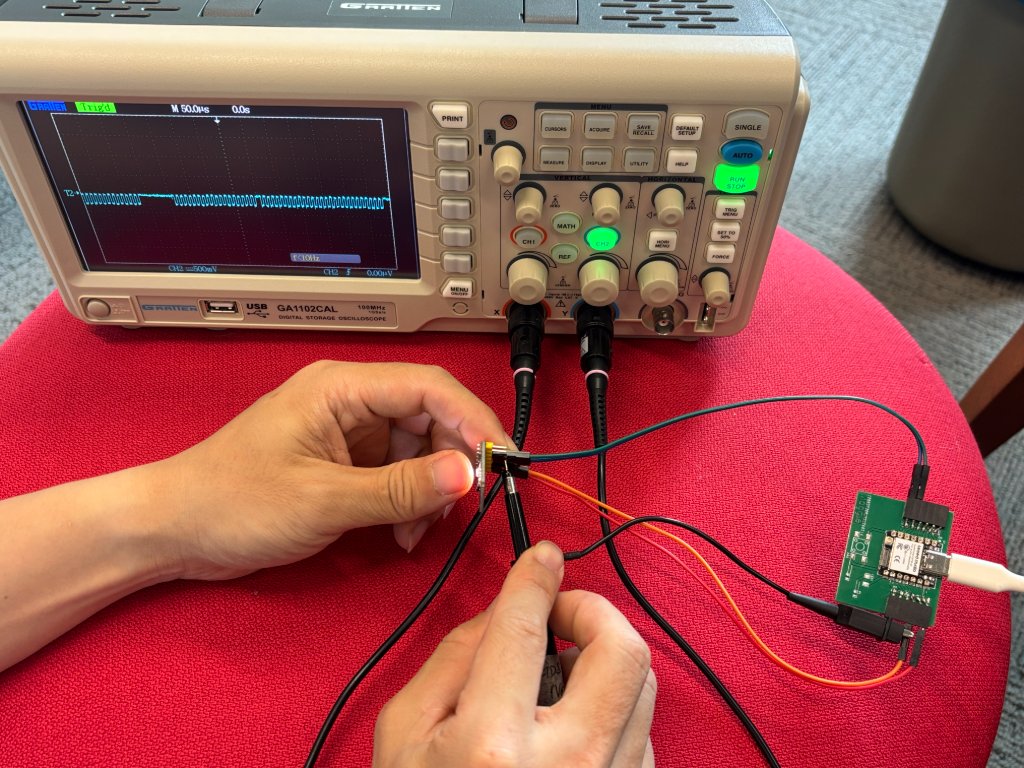
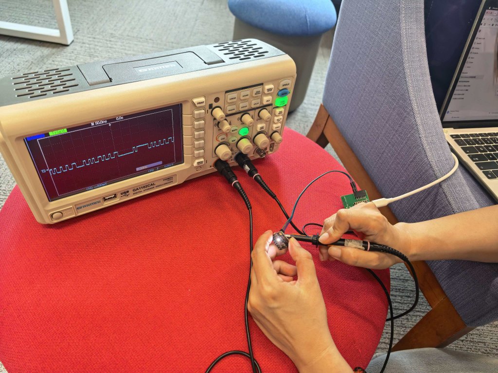
Connect the ground chip with the ESP32-S3 board GND, and the SCL pin with the ESP32-S3 board SCL pin.
Oscilloscope probe connections
Oscilloscope

        Probe -------------------- SCL

        Ground ------------------- GND
Setting up oscilloscope
| Parameter | Recommended value |
|---|---|
| Probe | 10× |
| Vertical | 1 V/div |
| Horizontal | 20 μs/div |
| Trigger | Edge |
| Trigger Source | CH1 |
| Trigger Mode | Rising |
| Trigger Level | 1.5 V |
Source file (Arduino sketch): TCS3472_XIAO_week09.ino — XIAO ESP32-C3 + TCS3472 color sensor (same code as on this page).